Special thanks to Jeff Duntemann, who made it all happen, to Noah Oremland, who proofed every word, encouraged me, and even laughed at my jokes, and to Amy Davis of Scott, Foresman & Co., who made this book possible. Thanks also to Tom Blakeslee, John T. Cockerham, Dan Gochnauer, Dan Illowsky, Bob Jervis, Dave Miller, Ted Mirecki, Phil Mummah, Kent Porter, and Tom Wilson for information, feedback and encouragement. Finally, thanks to Orion Instruments for the use of an OmniLab.
For Shay and Emily.
Trademarks
Term
Company
OS/2
Microsoft Corp.
Microsoft Macro Assembler
Microsoft Corp.
Microsoft Linker
Microsoft Corp.
Symdeb
Microsoft Corp.
CodeView
Microsoft Corp.
MS-DOS
Microsoft Corp.
Turbo C
Borland International, Inc.
Turbo Debugger
Borland International, Inc.
Turbo Linker
Borland International, Inc.
Turbo Assembler
Borland International, Inc.
Sidekick
Borland International, Inc.
OPTASM
SLR Systems
OmniLab
Orion Instruments, Inc.
IBM
International Business Machines Corp.
PC
International Business Machines Corp.
AT
International Business Machines Corp.
PS/2
International Business Machines Corp.
PCjr
International Business Machines Corp.
Unix
AT&T
MacIntosh
Apple
Wordstar
Micropro International
Visicalc
Visicorp
Amiga
Commodore
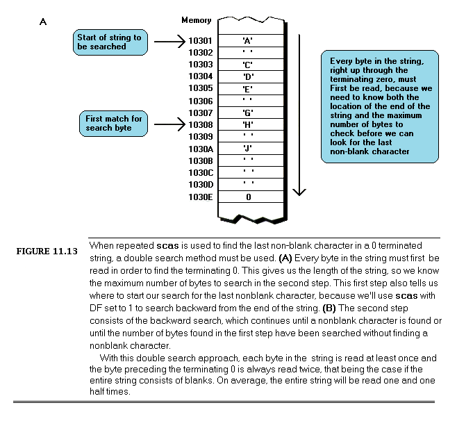
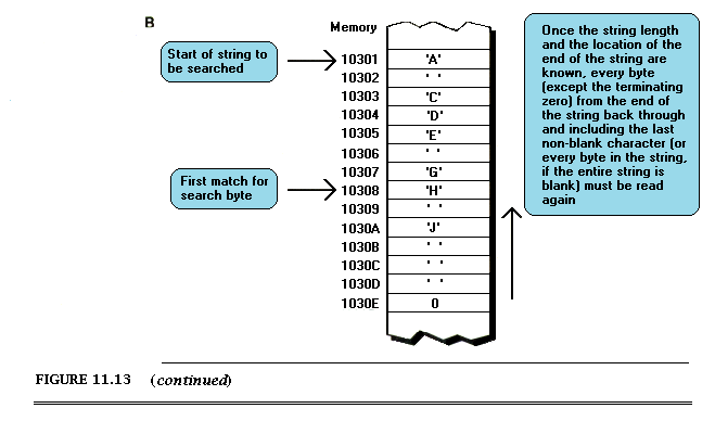
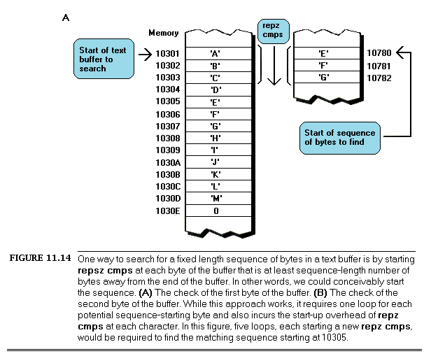
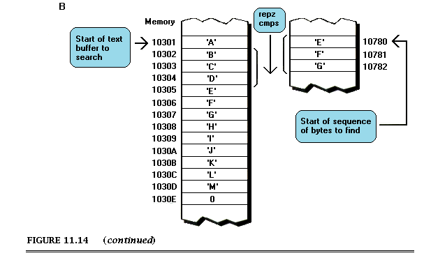
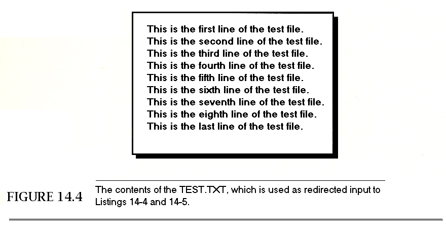
Introduction: Pushing the Envelope
This is the book I wished for with all my heart seven years ago, when I started programming the IBM PC: the book that unlocks the secrets of writing superb assembly-language code. There was no such book then, so I had to learn the hard way, through experimentation and through trial and error. Over the years, I waited in vain for that book to appear; I looked everywhere without success for a book about advanced assembly-language programming, a book written specifically for assembly-language programmers who want to get better, rather than would-be assembly-language programmers. I’m sure many of you have waited for such a book as well. Well, wait no longer: this is that book.
The Zen of Assembly Language assumes that you’re already familiar with assembly language. Not an expert, but at least acquainted with the registers and instructions of the 8088, and with the use of one of the popular PC assemblers. Your familiarity with assembly language will allow us to skip over the droning tutorials about the use of the assembler and the endless explanations of binary arithmetic that take up hundreds of pages in introductory books. We’re going to jump into high-performance programming right from the start, and when we come up for air 16 chapters from now, your view of assembly language will be forever altered for the better. Then we’ll leap right back into Volume II, applying our newfound knowledge of assembly language to ever-more-sophisticated programming tasks.
In short, The Zen of Assembler is about nothing less than how to become the best assembly-language programmer you can be.
Why Assembly Language?
For years, people have been predicting — hoping for — the demise of assembly language, claiming that the world is ready to move on to less primitive approaches to programming… and for years, the best programs around have been written in assembly language. Why is this? Simply because assembly language is hard to work with, but — properly used — produces programs of unparalleled performance. Mediocre programmers have a terrible time working with assembly language; on the other hand, assembly language is, without fail, the language that PC gurus use when they need the best possible code.
Which brings us to you.
Do you want to be a guru? I’d imagine so, if you’re reading this book. You’ve set yourself an ambitious and difficult goal, and your success is far from guaranteed. There’s no sure-fire recipe for becoming a guru, any more than there’s a recipe for becoming a chess grand master. There is, however, one way you can greatly improve your chances: become an expert assembly language programmer. Assembly language won’t by itself make you a guru — but without it you’ll never reach your full potential as a programmer.
Why is assembly language so important in this age of optimizing compilers and program generators? Assembly language is fundamentally different from all other languages, as we’ll see throughout The Zen of Assembly Language. Assembly language lets you use every last resource of the PC to push the performance envelope; only in assembly language can you press right up against the inherent limits of the PC.
If you aren’t pushing the envelope, there’s generally no reason to program in assembler. High-level languages are certainly easier to use, and nowadays most high-level languages let you get at the guts of the PC — display memory, DOS functions, interrupt vectors, and so on — without having to resort to assembler. If, in the other hand, you’re striving for the sort of performance that will give your programs snappy interfaces and crackling response times, you’ll find assembly language to be almost magical, for no other language even approaches assembler for sheer speed.
Of course, no one tests the limits of the PC with their first assembler program; that takes time and practice. While many PC programmers know something about assembler, few are experts. The typical programmer has typed in the assembler code from an article or two, read a book about assembler programming, and perhaps written a few assembler programs of his own — but doesn’t yet feel that he has mastered the language. If you fall into this category, you’ve surely sensed the remarkable potential of assembler, but you’re also keenly aware of how hard it is to write good assembler code and how much you have yet to learn. In all likelihood, you’re not sure how to sharpen your assembler skills and take that last giant step toward mastery of your PC.
This book is for you.
Welcome to the most exciting and esoteric aspect of the IBM PC. The Zen of Assembly Language will teach you how to create blindingly fast code for the IBM PC. More important still, it will teach you how to continue to develop your assembler programming skills on your own. The Zen of Assembly Language will show you a way to learn what you need to know as the need arises, and it is that way of learning that will serve you well for years to come. There are facts and code aplenty in this book and in the companion volume, but it is a way of thinking and learning that lies at the heart of The Zen of Assembly Language.
Don’t take the title to mean that this is a mystical book in any way. In the context of assembly-language programming, Zen is a technique that brings intuition and non-obvious approaches to bear on difficult problems and puzzles. If you would rather think of high-performance assembler programming as something more mundane, such as right-brained thinking or plain old craftsmanship, go right ahead; good assembler programming is a highly individualized process.
The Zen of Assembly Language is specifically about assembly language for the IBM PC (and, by definition, compatible computers). In particular, the bulk of this volume will focus on the capabilities of the 8088 processor that lies at the heart of the PC. However, many of the findings and almost all of the techniques I’ll discuss can also be applied to assembly-language programming for the other members of Intel’s 808X processor family, including the 80286 and 80386 processors, as we’ll see toward the end of this volume. The Zen of Assembly Language doesn’t much apply to computers built around other processors, such as the 68XXX family, the Z80, the 8080, or the 6502, since a great deal of the Zen of assembly language in the case of the IBM PC derives from the highly unusual architecture of the 808X family. (In fact, the processors in the 808X family lend themselves beautifully to assembly language, much more so than other currently-popular processors.)
While I will spend a chapter looking specifically at the 80286 found in the AT and PS/2 Models 50 and 60 and at the 80386 found in the PS/2 Model 80, I’ll concentrate primarily on the 8088 processor found in the IBM PC and XT, for a number of reasons. First, there are at least 15,000,000 8088-based computers around, ensuring that good 8088 code isn’t going to go out of style anytime soon. Second, the 8088 is far and away the slowest of the processors used in IBM-compatible computers, so no matter how carefully code is tailored to the subtleties of the 8088, it’s still going to run much faster on an 80286 or 80386. Third, many of the concepts I’ll present regarding the 8088 apply to the 80286 and 80386 as well, but to a different degree. Given that there are simply too many processors around to cover in detail (and the 80486 on the way), I’d rather pay close attention to the 8088, the processor for which top-quality code is most critical, and provide you with techniques that will allow you to learn on your own how best to program other processors.
We’ll return to this topic in Chapter 15, when we will in fact discuss other 808X-family processors, but for now, take my word for it: when it comes to optimization, the 8088 is the processor of choice.
What You’ll Need
The tools you’ll need to follow this book are simple: a text editor to create ASCII program files, the Microsoft Macro Assembler version 5.0 or a compatible assembler (Turbo Assembler is fine) to assemble programs, and the Microsoft Linker or a compatible linker to link programs into an executable form.
There are several types of reference material you should have available as you pursue assembler mastery. You will certainly want a general reference on 8088 assembler. The 8086 Book, written by Rector and Alexy and published by Osborne/McGraw-Hill, is a good reference, although you should beware of its unusually high number of typographic errors. Also useful is the spiral-bound reference manual that comes with MASM, which contains an excellent summary of the instruction sets of the 8088, 8086, 80186, 80286, and 80386. IBM’s hardware, BIOS, and DOS technical reference manuals are also useful references, containing as they do detailed information about the resources available to assembler programmers.
If you’re the type who digs down to the hardware of the PC in the pursuit of knowledge, you’ll find Intel’s handbooks and reference manuals to be invaluable (albeit none too easy to read), since Intel manufactures the 8088 and many of the support chips used in the PC. There’s simply no way to understand what a hardware component is capable of doing in the context of the PC without a comprehensive description of everything that part can do, and that’s exactly what Intel’s literature provides.
Finally, keep an eye open for articles on assembly-language programming. Articles provide a steady stream of code from diverse sources, and are your best sources of new approaches to assembler programming.
By the way, the terms “assembler” and “assembly-language” are generally interchangeable. While “assembly-language” is perhaps technically more accurate, since “assembler” also refers to the software that assembles assembly-language code, “assembler” is a widely-used shorthand that I’ll use throughout this book. Similarly, I’ll use “the Zen of assembler” as shorthand for “the Zen of assembly language.”
Odds and Ends
I’d like to identify the manufacturers of the products I’ll refer to in this volume. Microsoft makes the Microsoft Macro Assembler (MASM), the Microsoft Linker (LINK), CodeView (CV), and Symdeb (SYMDEB). Borland International makes Turbo Assembler (TASM), Turbo C (TC), Turbo Link (TLINK), and Turbo Debugger (TD). SLR Systems makes OPTASM, an assembler. Finally, Orion Instruments makes OmniLab, which integrates high-performance oscilloscope, logic analyzer, stimulus generator, and disassembler instrumentation in a single PC-based package.
In addition, I’d like to point out that while I’ve made every effort to ensure that the code in this volume works as it should, no one’s perfect. Please let me know if you find bugs. Also, please let me know what works for you and what doesn’t in this book; teaching is not a one-way street. You can write me at:
1599 Bittern Drive
Sunnyvale, CA 94087
The Path to the Zen of Assembler
The Zen of Assembly Language consists of four major parts, contained in two volumes. Parts I and II are in this volume, Volume I, while Parts III and IV are in Volume II, The Zen of Assembly Language: The Flexible Mind. While the book you’re reading stands on its own as a tutorial in high-performance assembler code, the two volumes together cover the whole of superior assembler programming, from hardware to implementation. I strongly recommend that you read both. The four parts of The Zen of Assembly Language are organized as follows.
Part I introduces the concept of the Zen of assembler, and presents the tools we’ll use to delve into assembler code performance.
Part II covers various and sundry pieces of knowledge about assembler programming, examines the resources available when programming the PC, and probes fundamental hardware aspects that affect code performance.
Part III (in Volume II) examines the process of creating superior code, combining the detailed knowledge of Part II with varied and often unorthodox coding approaches.
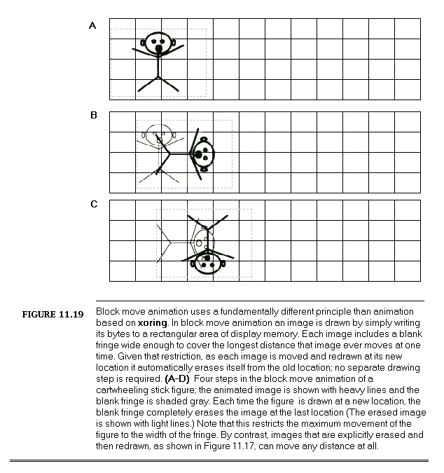
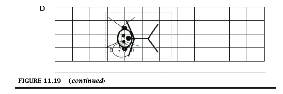
Part IV (also in Volume II) illustrates the Zen of assembler in the form of a working animation program.
In general, Parts I and II discuss the raw stuff of performance, while Parts III and IV show how to integrate that raw performance with algorithms and applications, although there is considerable overlap. The four parts together teach all aspects of the Zen of assembler: concept, knowledge, the flexible mind, and implementation. Together, we will follow that path down the road to mastery of the IBM PC.
Shall we begin?
Michael Abrash
Sunnyvale, CA
May 29, 1989
Chapter 1: Zen?
What is the Zen of assembler? Many things: a set of programming skills that lets you write incredibly fast programs, a technique for turning ideas into code, a process of looking at problems in new ways and finding fresh solutions, and more. Perhaps a brief story would be the best way to introduce the Zen of assembler.
The Zen of Assembler in a Nutshell
Some time ago, I was asked to work over a critical assembler subroutine in order to make it run as fast as possible. The task of the subroutine was to construct a nibble out of four bits read from different bytes, rotating and combining the bits so that they ultimately ended up neatly aligned in bits 3-0 of a single byte. (In case you’re curious, the object was to construct a 16-color pixel from bits scattered over 4 bytes.) I examined the subroutine line by line, saving a cycle here and a cycle there, until the code truly seemed to be optimized. When I was done, the key part of the code looked something like this:
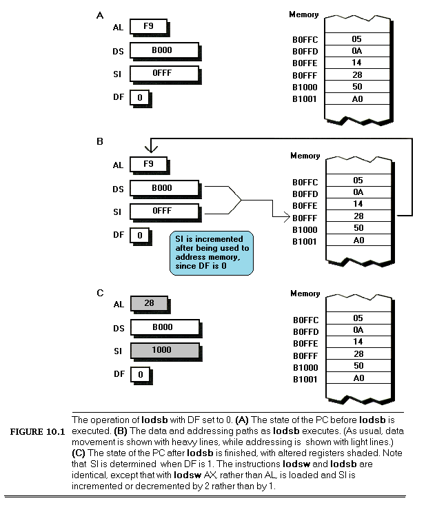
LoopTop:lodsb;get the next byte to extract a bit fromandal,ah;isolate the bit we wantrolal,cl;rotate the bit into the desired positionorbl,al;insert the bit into the final nibbledeccx;the next bit goes 1 place to the rightdecdx;count down the number of bitsjnz LoopTop ;process the next bit, if any
Now, it’s hard to write code that’s much faster than seven assembler instructions, only one of which accesses memory, and most programmers would have called it a day at this point; still, something bothered me, so I spent a bit of time going over the code again. Suddenly, the answer struck me — the code was rotating each bit into place separately, so that a multi-bit rotation was being performed every time through the loop, for a total of four separate time-consuming multi-bit rotations! While the instructions themselves were individually optimized, the overall approach did not make the best possible use of the instructions.
I changed the code to the following:
LoopTop:lodsb;get the next byte to extract a bit fromandal,ah;isolate the bit we wantorbl,al;insert the bit into the final nibblerolbl,1;make room for the next bitdecdx;count down the number of bitsjnz LoopTop ;process the next bit, if anyrolbl,cl;rotate all four bits into their final; positions at the same time
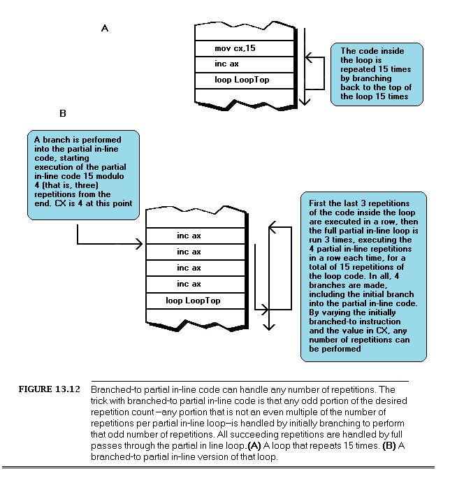
This moved the costly multi-bit rotation out of the loop, so that it was performed just once, rather than four times. While the new code may not look much different from the original, and in fact still contains exactly the same number of instructions, the performance of the entire subroutine improved by about 10% from just this one change. (Incidentally, that wasn’t the end of the optimization; I eliminated the dec and jnz instructions by expanding the four iterations of the loop into in-line code — but that’s a tale for another chapter.)
The point is this: to write truly superior assembler programs, you need to know what the various instructions do and which instructions execute fastest… and more. You must also learn to look at your programming problems from a variety of perspectives, so that you can put those fast instructions to work in the most effective ways. And, that, in a nutshell, is the Zen of assembler.
Assembler is Fundamentally Different from Other Languages
Is it really so hard as all that to write good assembler code for the IBM PC? Yes! Thanks to the decidedly quirky nature of the 8088 processor, assembly language differs fundamentally from other languages, and is undeniably harder to work with. On the other hand, the potential of assembler code is much greater than that of other languages, as well. The Zen of assembler is the way to tap that potential.
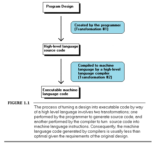
To understand why this is, consider how a program gets written. A programmer examines the requirements of an application, designs a solution at some level of abstraction, and then makes that design come alive in a code implementation. If not handled properly, the transformation that takes place between conception and implementation can reduce performance tremendously; for example, a programmer who implements a routine to search a list of 100,000 sorted items with a linear rather than binary search will end up with a disappointingly slow program.
No matter how well an implementation is derived from the corresponding design, however, high-level languages like C and Pascal inevitably introduce additional transformation inefficiencies, as shown in Figure 1.1.
High-level languages provide artificial environments that lend themselves relatively well to human programming skills, in order to ease the transition from design to implementation. The price for this ease of implementation is a considerable loss of efficiency in transforming source code into machine language. This is particularly true given that the 8088, with its specialized memory-addressing instructions and segmented memory architecture, does not lend itself particularly well to compiler design.
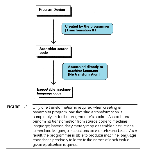
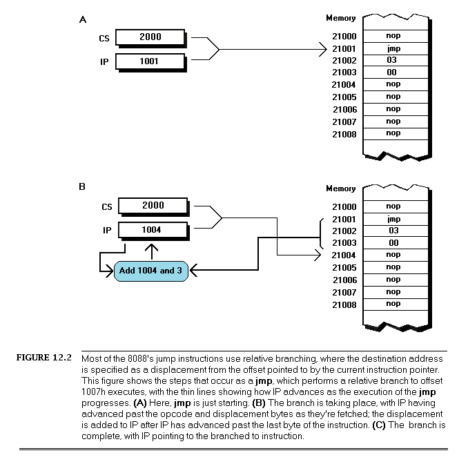
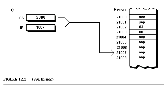
Assembler, on the other hand, is simply a human-oriented representation of machine language. As a result, assembler provides a difficult programming environment — the bare hardware and systems software of the computer — but properly constructed assembler programs suffer no transformation loss, as shown in Figure 1.2.
The key, of course, is the programmer, since in assembler the programmer must essentially perform the transformation from the application specification to machine language entirely on his own. (The assembler merely handles the direct translation from assembler to machine language.)
The first part of the Zen of assembler, then, is self-reliance. An assembler is nothing more than a tool to let you design machine-language programs without having to think in hexadecimal codes, so assembly-language programmers — unlike all other programmers — must take full responsibility for the quality of their code. Since assemblers provide little help at any level higher than the generation of machine language, the assembler programmer must be capable both of coding any programming construct directly and of controlling the PC at the lowest practical level — the operating system, the BIOS, the hardware where necessary. High-level languages handle most of this transparently to the programmer, but in assembler everything is fair — and necessary — game, which brings us to another aspect of the Zen of assembler.
Knowledge.
Knowledge
In the IBM PC world, you can never have enough knowledge, and every item you add to your store will make your programs better. Thorough familiarity with both the operating system and BIOS interfaces is important; since those interfaces are well-documented and reasonably straightforward, my advice is to get IBM’s documentation and a good book or two and bring yourself up to speed. Similarly, familiarity with the hardware of the IBM PC is required. While that topic covers a lot of ground — display adapters, keyboards, serial ports, printer ports, timer and DMA channels, memory organization, and more — most of the hardware is well-documented, and articles about programming major hardware components appear frequently, so this sort of knowledge can be acquired readily enough.
The single most critical aspect of the hardware, and the one about which it is hardest to learn, is the 8088 processor. The 8088 has a complex, irregular instruction set, and, unlike most processors, the 8088 is neither straightforward nor well-documented as regards true code performance. What’s more, assembler is so difficult to learn that most articles and books which present assembler code settle for code that works, rather than code that pushes the 8088 to its limits. In fact, since most articles and books are written for inexperienced assembler programmers, there is very little information of any sort available about how to generate high-quality assembler code for the 8088. As a result, knowledge about programming the 8088 effectively is by far the hardest knowledge to gather. A good portion of this book is devoted to seeking out such knowledge. Be forewarned, though: no matter how much you learn about programming the IBM PC in assembler, there’s always more to discover.
The Flexible Mind
Is the never-ending collection of information all there is to the Zen of assembler, then? Hardly. Knowledge is simply a necessary base on which to build. Let’s take a moment to examine the objectives of good assembler programming, and the remainder of the Zen of assembler will fall into place.
Basically, there are only two possible objectives to high-performance assembler programming: given the requirements of the application, keep to a minimum either the number of processor cycles the program takes to run or the number of bytes in the program, or some combination of both. We’ll look at ways to achieve both objectives, but we’ll more often be concerned with saving cycles than saving bytes, for the PC offers relatively more memory than it does processing horsepower. In fact, we’ll find that 2-to-3 times performance improvements over tight assembler code are often possible if we’re willing to expend additional bytes in order to save cycles. It’s not always desirable to use such techniques to speed up code, due to the heavy memory requirements — but it is almost always possible.
You will notice that my short list of objectives for high-performance assembler programming does not include traditional objectives such as easy maintenance and speed of development. Those are indeed important considerations — to persons and companies that develop and distribute software. People who actually buy software, on the other hand, care only about how well that software performs, not how it was developed. Nowadays, developers spend so much time focusing on such admittedly important issues as code maintainability and reusability, source code control, choice of development environment, and the like that they forget rule #1: from the user’s perspective, performance is fundamental. Comment your code, design it carefully, and write non-time-critical portions in a high-level language, if you wish — but when you write the portions that interact with the user and/or affect response time, performance must be your paramount objective, and assembler is the path to that goal.
Knowledge of the sort described earlier is absolutely essential to fulfilling either of the objectives of assembler programming. What that knowledge doesn’t by itself do is meet the need to write code that both performs to the requirements of the application at hand and operates in the PC environment as efficiently as possible. Knowledge makes that possible, but your programming instincts make it happen. And it is that intuitive, on-the-fly integration of a program specification and a sea of facts about the PC that is the heart of the Zen of assembler.
As with Zen of any sort, mastering the Zen of assembler is more a matter of learning than of being taught. You will have to find your own path of learning, although I will start you on your way with this book. The subtle facts and examples I provide will help you gain the necessary experience, but you must continue the journey on your own. Each program you create will expand your programming horizons and increase the options available to you in meeting the next challenge. The ability of your mind to find surprising new and better ways to craft superior code from a concept — the flexible mind, if you will — is the linchpin of good assembler code, and you will develop this skill only by doing.
Never underestimate the importance of the flexible mind. Good assembler code is better than good compiled code. Many people would have you believe otherwise, but they’re wrong. That doesn’t mean high-level languages are useless; far from it. High-level languages are the best choice for the majority of programmers, and for the bulk of the code of most applications. When the best code — the fastest or smallest code possible — is needed, though, assembler is the only way to go.
Simple logic dictates that no compiler can know as much about what a piece of code needs to do or adapt as well to those needs as the person who wrote the code. Given that superior information and adaptability, an assembly-language programmer can generate better code than a compiler, all the more so given that compilers are constrained by the limitations of high-level languages and by the process of transformation from high-level to machine language. Consequently, carefully optimized assembler is not just the language of choice but the only choice for the 1% to 10% of all code — usually consisting of small, well-defined subroutines — that determines overall program performance, and is the only choice for code that must be as compact as possible, as well. In the run-of-the-mill, non-time-critical portions of your programs, it makes no sense to waste time and effort on writing optimized assembler code — concentrate your efforts on loops and the like instead — but in those areas where you need the finest code quality, accept no substitutes.
Note that I said that an assembler programmer can generate better code than a compiler, not will generate better code. While it is true that good assembler code is better than good compiled code, it is also true that bad assembler code is often much worse than bad compiled code; since the assembler programmer has so much control over the program, he or she has unlimited opportunity to waste cycles and bytes. The sword cuts both ways, and good assembler code requires more, not less, forethought and planning than good code written in a high-level language.
The gist of all this is simply that good assembler programming is done in the context of a solid overall framework unique to each program, and the flexible mind is the key to creating that framework and holding it together.
Where to Begin?
To summarize, the Zen of assembler is a combination of knowledge, perspective, and way of thought that makes possible the genesis of first-rate assembler programs. Given that, where to begin our explorations of the Zen of assembler? Development of the flexible mind is an obvious step. Still, the flexible mind is no better than the knowledge at its disposal. We have much knowledge to acquire before we can begin to discuss the flexible mind, and in truth we don’t even know yet how to acquire knowledge about 8088 assembler, let alone what that knowledge might be. The first step in the journey toward the Zen of assembler, then, would seem to be learning how to learn.
Chapter 2: Assume Nothing
When you’re pushing the envelope in assembler, you’re likely to become more than a little compulsive about finding approaches that let you wring more speed from your computer. In the process, you’re bound to make mistakes, which is fine — so long as you watch for those mistakes and learn from them.
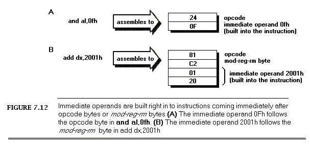
A case in point: a few years back, I came across an article about 8088 assembly language called “Optimizing for Speed.” Now, “optimize” is not a word to be used lightly; Webster’s Ninth New Collegiate Dictionary defines optimize as “to make as perfect, effective, or functional as possible,” which certainly leaves little room for error. The author had, however, chosen a small, well-defined 8088 assembly-language routine to refine, consisting of about 30 instructions that did nothing more than expand 8 bits to 16 bits by duplicating each bit. (We’ll discuss this code and various optimizations to it at length in Chapter 7.)
The author of “Optimizing” had clearly fine-tuned the code with care, examining alternative instruction sequences and adding up cycles until he arrived at an implementation he calculated to be nearly 50% faster than the original routine. In short, he had used all the information at his disposal to improve his code, and had, as a result, saved cycles by the bushel. There was, in fact, only one slight problem with the optimized version of the routine…
It ran slower than the original version!
As diligent as the author had been, he had nonetheless committed a cardinal sin of 8088 assembly-language programming: he had assumed that the information available to him was both correct and complete. While the execution times provided by Intel for its processors are indeed correct, they are incomplete; the other — and often more important — part of code performance is instruction fetch time, a topic to which I will return in later chapters.
Had the author taken the time to measure the true performance of his code, he wouldn’t have put his reputation on the line with relatively low-performance code. What’s more, had he measured the performance of his code and found it to be unexpectedly slow, curiosity might well have led him to experiment further and thereby add to his store of reliable information about the 8088, and there you have an important part of the Zen of assembler: after crafting the best code possible, check it in action to see if it’s really doing what you think it is. If it’s not behaving as expected, that’s all to the good, since solving mysteries is the path to knowledge. You’ll learn more in this way, I assure you, than from any manual or book on assembly-language.
Assume nothing. I cannot emphasize this strongly enough — when you care about performance, do your best to improve the code and then measure the improvement. If you don’t measure performance, you’re just guessing, and if you’re guessing, you’re not very likely to write top-notch code.
Ignorance about true performance can be costly. When I wrote video games for a living, I spent days at a time trying to wring more performance from my graphics drivers. I rewrote whole sections of code just to save a few cycles, juggled registers, and relied heavily on blurry-fast register-to-register shifts and adds. As I was writing my last game, I discovered that the program ran perceptibly faster if I used look-up tables instead of shifts and adds for my calculations. It shouldn’t have run faster, according to my cycle counting, but it did. In truth, instruction fetching was rearing its head again, as it often does when programming the 8088, and the fetching of the shifts and adds was taking as much as four times the nominal execution time of those instructions.
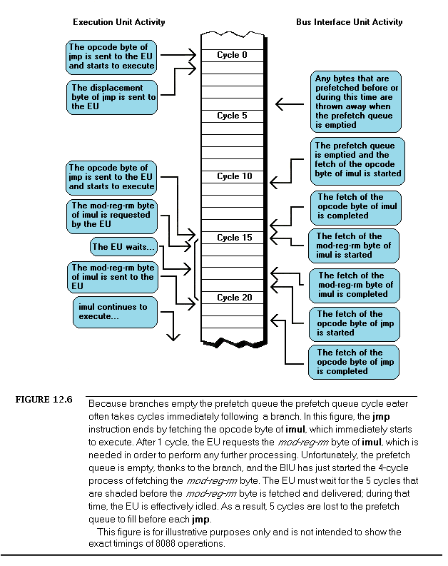
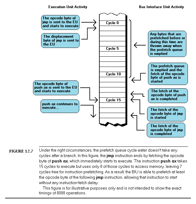
Ignorance can also be responsible for considerable wasted effort. I recall a debate in the letters column of one computer magazine about exactly how quickly text can be drawn on a Color/Graphics Adapter screen without causing snow. The letter writers counted every cycle in their timing loops, just as the author in the story that started this chapter had. Like that author, the letter writers had failed to take the prefetch queue into account. In fact, they had neglected the effects of video wait states as well, so the code they discussed was actually much slower than their estimates. The proper test would, of course, have been to run the code to see if snow resulted, since the only true measure of code performance is observing it in action.
The Zen Timer
One key to mastering the Zen of assembler is clearly a tool with which to measure code performance. The most accurate way to measure performance is with expensive hardware, but reasonable measurements at no cost can be made with the PC’s 8253 timer chip, which counts at a rate of slightly over 1,000,000 times per second. The 8253 can be started at the beginning of a block of code of interest and stopped at the end of that code, with the resulting count indicating how long the code took to execute with an accuracy of about 1 microsecond. (A microsecond is one -millionth of a second, and is abbreviated us). To be precise, the 8253 counts once every 838.1 nanoseconds. (A nanosecond is one-billionth of a second, and is abbreviated ns).
Listing 2-1 shows 8253-based timer software, consisting of three subroutines: ZTimerOn, ZTimerOff, and ZTimerReport. For the remainder of this book, I’ll refer to these routines collectively as the “Zen timer.”
The Zen Timer is a Means, Not an End
We’re going to spend the rest of this chapter seeing what the Zen timer can do, examining how it works, and learning how to use it. The Zen timer will be our primary tool for the remainder of The Zen of Assembly Language, so it’s essential that you learn what the Zen timer can do and how to use it. On the other hand, it is by no means essential that you understand exactly how the Zen timer works. (Interesting, yes; essential, no.)
In other words, the Zen timer isn’t really part of the knowledge we seek; rather, it’s one tool with which we’ll acquire that knowledge. Consequently, you shouldn’t worry if you don’t fully grasp the inner workings of the Zen timer. Instead, focus on learning how to use the timer, since we will use it heavily throughout The Zen of Assembly Language.
Starting the Zen Timer
ZTimerOn is called at the start of a segment of code to be timed. ZTimerOn saves the context of the calling code, disables interrupts, sets timer 0 of the 8253 to mode 2 (divide-by-N mode), sets the initial timer count to 0, restores the context of the calling code, and returns. (I’d like to note that while Intel’s documentation for the 8253 seems to indicate that a timer won’t reset to 0 until it finishes counting down, in actual practice timers seems to reset to 0 as soon as they’re loaded.)
Two aspects of ZTimerOn are worth discussing further. One point of interest is that ZTimerOn disables interrupts. (ZTimerOff later restores interrupts to the state they were in when ZTimerOn was called.) Were interrupts not disabled by ZTimerOn, keyboard, mouse, timer, and other interrupts could occur during the timing interval, and the time required to service those interrupts would incorrectly and erratically appear to be part of the execution time of the code being measured. As a result, code timed with the Zen timer should not expect any hardware interrupts to occur during the interval between any call to ZTimerOn and the corresponding call to ZTimerOff, and should not enable interrupts during that time.
Time and the PC
A second interesting point about ZTimerOn is that it may introduce some small inaccuracy into the system clock time whenever it is called. To understand why this is so, we need to examine the way in which both the 8253 and the PC’s system clock (which keeps the current time) work.
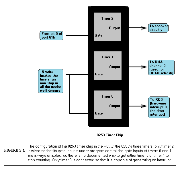
The 8253 actually contains three timers, as shown in Figure 2.1. All three timers are driven by the system board’s 14.31818 megahertz crystal, divided by 12 to yield a 1.19318-MHz clock to the timers, so the timers count once every 838.1 ns. Each of the three timers counts down in a programmable way, generating a signal on its output pin when it counts down to 0. Each timer is capable of being halted at any time via a 0 level on its gate input; when a timer’s gate input is 1, that timer counts constantly. All in all, the 8253’s timers are inherently very flexible timing devices; unfortunately, much of that flexibility depends on how the timers are connected to external circuitry, and in the PC the timers are connected with specific purposes in mind.
Timer 2 drives the speaker, although it can be used for other timing purposes when the speaker is not in use. As shown in Figure 2.1, timer 2 is the only timer with a programmable gate input in the PC; that is, timer 2 is the only timer which can be started and stopped under program control in the manner specified by Intel. On the other hand, the output of timer 2 is connected to nothing other than the speaker. In particular, timer 2 cannot generate an interrupt to get the 8088’s attention.
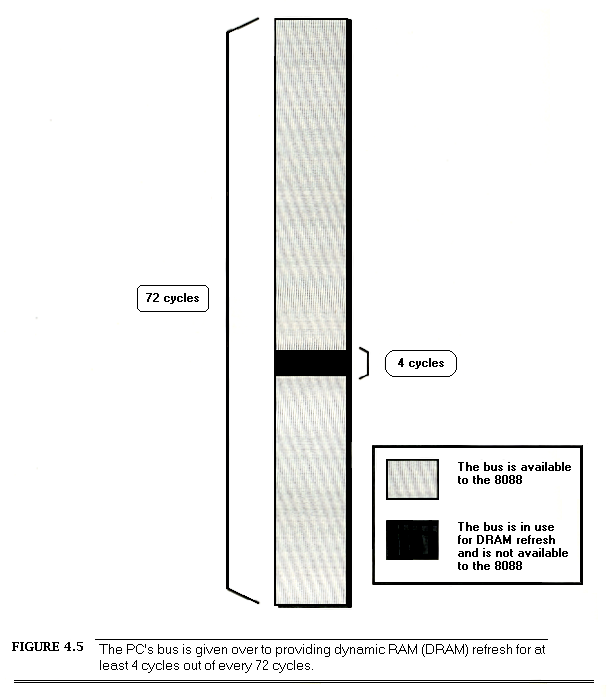
Timer 1 is dedicated to providing dynamic RAM refresh, and should not be tampered with lest system crashes result.
Finally, timer 0 is used to drive the system clock. As programmed by the BIOS at power-up, every 65,536 (64 K) counts, or 54.925 milliseconds, timer 0 generates a rising edge on its output line. (A millisecond is one-thousandth of a second, and is abbreviated ms). This line is connected to the hardware interrupt 0 (IRQ0) line on the system board, so every 54.925 ms timer 0 causes hardware interrupt 0 to occur.
The interrupt vector for IRQ0 is set by the BIOS at power-up time to point to a BIOS routine, TIMER_INT, that maintains a time-of-day count. TIMER_INT keeps a 16-bit count of IRQ0 interrupts in the BIOS data area at address 0000:046C (all addresses are given in segment:offset hexadecimal pairs); this count turns over once an hour (less a few microseconds), and when it does, TIMER_INT updates a 16-bit hour count at address 0000:046E in the BIOS data area. This routine is the basis for the current time and date that DOS supports via functions 2Ah (2A hexadecimal) through 2Dh and by way of the DATE and TIME commands. Each timer channel of the 8253 can operate in any of 6 modes. Timer 0 normally operates in mode 3, square wave mode. In square wave mode, the initial count is counted down two at a time; when the count reaches zero, the output state is changed. The initial count is again counted down two at a time, and the output state is toggled back when the count reaches zero. The result is a square wave that changes state more slowly than the input clock by a factor of the initial count. In its normal mode of operation, timer 0 generates an output pulse that is low for about 27.5 ms and high for about 27.5 ms; this pulse is sent to the 8259 interrupt controller, and its rising edge generates a timer interrupt once every 54.925 ms.
Square wave mode is not very useful for precision timing because it counts down by 2 twice per timer interrupt, thereby rendering exact timings impossible. Fortunately, the 8253 offers another timer mode, mode 2 (divide-by-N mode), which is both a good substitute for square wave mode and a perfect mode for precision timing.
Divide-by-N mode counts down by 1 from the initial count. When the count reaches zero, the timer turns over and starts counting down again without stopping, and a pulse is generated for a single clock period. While the pulse is not held for nearly as long as in square wave mode, it doesn’t matter, since the 8259 interrupt controller is configured in the PC to be edge-triggered and hence cares only about the existence of a pulse from timer 0, not the duration of the pulse. As a result, timer 0 continues to generate timer interrupts in divide-by-N mode, and the system clock continues to maintain good time.
Why not use timer 2 instead of timer 0 for precision timing? After all, timer 2 has a programmable gate input and isn’t used for anything but sound generation. The problem with timer 2 is that its output can’t generate an interrupt; in fact, timer 2 can’t do anything but drive the speaker. We need the interrupt generated by the output of timer 0 to tell us when the count has overflowed, and we will see shortly that the timer interrupt also makes it possible to time much longer periods than the Zen timer shown in Listing 2-1 supports.
In fact, the Zen timer shown in Listing 2-1 can only time intervals of up to about 54 ms in length, since that is the period of time that can be measured by timer 0 before its count turns over and repeats. 54 ms may not seem like a very long time, but an 8088 can perform more than 1000 divides in 54 ms, and division is the single instruction the 8088 performs most slowly. If a measured period turns out to be longer than 54 ms (that is, if timer 0 has counted down and turned over), the Zen timer will display a message to that effect. A long-period Zen timer for use in such cases will be presented later in this chapter.
The Zen timer determines whether timer 0 has turned over by checking to see whether an IRQ0 interrupt is pending. (Remember, interrupts are off while the Zen timer runs, so the timer interrupt cannot be recognized until the Zen timer stops and enables interrupts.) If an IRQ0 interrupt is pending, then timer 0 has turned over and generated a timer interrupt. Recall that ZTimerOn initially sets timer 0 to 0, in order to allow for the longest possible period — about 54 ms — before timer 0 reaches 0 and generates the timer interrupt.
Now we’re ready to look at the ways in which the Zen timer can introduce inaccuracy into the system clock. Since timer 0 is initially set to 0 by the Zen timer, and since the system clock ticks only when timer 0 counts off 54.925 ms and reaches 0 again, an average inaccuracy of one-half of 54.925 ms, or about 27.5 ms, is incurred each time the Zen timer is started. In addition, a timer interrupt is generated when timer 0 is switched from mode 3 to mode 2, advancing the system clock by up to 54.925 ms, although this only happens the first time the Zen timer is run after a warm or cold boot. Finally, up to 54.925 ms can again be lost when ZTimerOff is called, since that routine again sets the timer count to zero. Net result: the system clock will run up to 110 ms (about a ninth of a second) slow each time the Zen timer is used.
Potentially far greater inaccuracy can be incurred by timing code that takes longer than about 110 ms to execute. Recall that all interrupts, including the timer interrupt, are disabled while timing code with the Zen timer. The 8259 interrupt controller is capable of remembering at most one pending timer interrupt, so all timer interrupts after the first one during any given Zen timing interval are ignored. Consequently, if a timing interval exceeds 54.9 ms, the system clock effectively stops 54.9 ms after the timing interval starts and doesn’t restart until the timing interval ends, losing time all the while.
The effects on the system time of the Zen timer aren’t a matter for great concern, as they are temporary, lasting only until the next warm or cold boot. Systems that have battery-backed clocks, such as ATs, automatically reset the correct time whenever the computer is booted, and systems without battery-backed clocks prompt for the correct date and time when booted. Also, even repeated use of the Zen timer usually makes the system clock slow by at most a total of a few seconds, unless code that takes much longer than 54 ms to run is timed (in which case the Zen timer will notify you that the code is too long to time.)
Nonetheless, it’s a good idea to reboot your computer at the end of each session with the Zen timer in order to make sure that the system clock is correct.
Stopping the Zen Timer
At some point after ZTimerOn is called, ZTimerOff must always be called to mark the end of the timing interval. ZTimerOff saves the context of the calling program, latches and reads the timer 0 count, converts that count from the countdown value that the timer maintains to the number of counts elapsed since ZTimerOn was called, and stores the result. Immediately after latching the timer 0 count — and before enabling interrupts — ZTimerOff checks the 8259 interrupt controller to see if there is a pending timer interrupt, setting a flag to mark that the timer overflowed if there is indeed a pending timer interrupt.
After that, ZTimerOff executes just the overhead code of ZTimerOn and ZTimerOff 16 times and averages and saves the results, in order to determine how many of the counts in the timing result just obtained were incurred by the overhead of the Zen timer rather than by the code being timed.
Finally, ZTimerOff restores the context of the calling program, including the state of the interrupt flag that was in effect when ZTimerOn was called to start timing, and returns.
One interesting aspect of ZTimerOff is the manner in which timer 0 is stopped in order to read the timer count. We don’t actually have to stop timer 0 to read the count; the 8253 provides a special latched read feature for the specific purpose of reading the count while a time is running. (That’s a good thing, too; we’ve no documented way to stop timer 0 if we wanted to, since its gate input isn’t connected. Later in this chapter, though, we’ll see that timer 0 can be stopped after all.) We simply tell the 8253 to latch the current count, and the 8253 does so without breaking stride.
Reporting Timing Results
ZTimerReport may be called to display timing results at any time after both ZTimerOn and ZTimerOff have been called. ZTimerReport first checks to see whether the timer overflowed (counted down to 0 and turned over) before ZTimerOff was called; if overflow did occur, ZTimerOff prints a message to that effect and returns. Otherwise, ZTimerReport subtracts the reference count (representing the overhead of the Zen timer) from the count measured between the calls to ZTimerOn and ZTimerOff, converts the result from timer counts to microseconds, and prints the resulting time in microseconds to the standard output.
Note that ZTimerReport need not be called immediately after ZTimerOff. In fact, after a given call to ZTimerOff, ZTimerReport can be called at any time right up until the next call to ZTimerOn.
You may want to use the Zen timer to measure several portions of a program while it executes normally, in which case it may not be desirable to have the text printed by ZTimerReport interfere with the program’s normal display. There are many ways to deal with this. One approach is removal of the invocations of the DOS print string function (INT 21h with AH equal to 9) from ZTimerReport, instead running the program under a debugger that supports screen flipping (such as Symdeb or Codeview), placing a breakpoint at the start of ZTimerReport, and directly observing the count in microseconds as ZTimerReport calculates it.
A second approach is modification of ZTimerReport to place the result at some safe location in memory, such as an unused portion of the BIOS data area.
A third approach is alteration of ZTimerReport to print the result over a serial port to a terminal or to another PC acting as a terminal. Similarly, Symdeb (and undoubtedly other debuggers as well) can be run from a remote terminal by running Mode to set up the serial port, then starting Symdeb and executing the command =com1 or =com2.
Yet another approach is modification of ZTimerReport to send the result to the printer via either DOS function 5 or BIOS interrupt 17h.
A final approach is to modify ZTimerReport to print the result to the auxiliary output via DOS function 4, and to then write and load a special device driver named AUX, to which DOS function 4 output would automatically be directed. This device driver could send the result anywhere you might desire. The result might go to the secondary display adapter, over a serial port, or to the printer, or could simply be stored in a buffer within the driver, to be dumped at a later time. (Credit for this final approach goes to Michael Geary, and thanks go to David Miller for passing the idea on to me.)
You may well want to devise still other approaches better suited to your needs than those I’ve presented. Go to it! I’ve just thrown out a few possibilities to get you started.
Notes on the Zen Timer
The Zen timer subroutines are designed to be near-called from assembly-language code running in the public segment Code. The Zen timer subroutines can, however, be called from any assembler or high-level language code that generates OBJ files that are compatible with the Microsoft Linker, simply by modifying the segment that the timer code runs in to match the segment used by the code being timed, or by changing the Zen timer routines to far procedures and making far calls to the Zen timer code from the code being timed. All three subroutines preserve all registers and all flags except the interrupt flag, so calls to these routines are transparent to the calling code.
If you do change the Zen timer routines to far procedures in order to call them from code running in another segment, be sure to make all the Zen timer routines far, including ReferenceZTimerOn and ReferenceZTimerOff. (You’ll have to put far ptr overrides on the calls from ZTimerOff to the latter two routines if you do make them far.) If the reference routines aren’t the same type — near or far — as the other routines, they won’t reflect the true overhead incurred by starting and stopping the Zen timer.
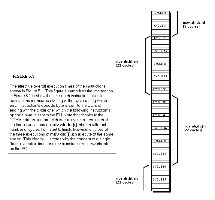
Please be aware that the inaccuracy that the Zen timer can introduce into the system clock time does not affect the accuracy of the performance measurements reported by the Zen timer itself. The 8253 counts once every 838 ns, giving us a count resolution of about 1 us, although factors such as the prefetch queue (as discussed below), dynamic RAM refresh, and internal timing variations in the 8253 make it perhaps more accurate to describe the Zen timer as measuring code performance with an accuracy of better than 10 us. In fact, we’ll see in Chapter 5 why the Zen timer is actually most accurate in assessing code performance when timing intervals longer than about 100 us. At any rate, we’re most interested using in the Zen timer to assess the relative performance of various code sequences — that is, using it to compare and tweak code — and the timer is more than accurate enough for that purpose.
The Zen timer works on all PC-compatible computers I’ve tested it on, including XTs, ATs, PS/2 computers, and 80386-based AT-compatible machines. Of course, I haven’t been able to test it on all PC-compatibles, but I don’t expect any problems; computers on which the Zen timer doesn’t run can’t truly be called “PC-compatible.”
On the other hand, there is certainly no guarantee that code performance as measured by the Zen timer will be the same on compatible computers as on genuine IBM machines, or that either absolute or relative code performance will be similar even on different IBM models; in fact, quite the opposite is true. For example, every PS/2 computer, even the relatively slow Model 30, executes code much faster than does a PC or XT. As another example, I set out to do the timings for this book on an XT -compatible computer, only to find that the computer wasn’t quite IBM-compatible as regarded code performance. The differences were minor, mind you, but my experience illustrates the risk of assuming that a specific make of computer will perform in a certain way without actually checking.
Not that this variation between models makes the Zen timer one whit less useful — quite the contrary. The Zen timer is an excellent tool for evaluating code performance over the entire spectrum of PC-compatible computers.
A Sample Use of the Zen Timer
Listing 2-2 shows a test-bed program for measuring code performance with the Zen timer. This program sets DS equal to CS (for reasons we’ll discuss shortly), includes the code to be measured from the file TESTCODE, and calls ZTimerReport to display the timing results. Consequently, the code being measured should be in the file TESTCODE, and should contain calls to ZTimerOn and ZTimerOff.
Listing 2-3 shows some sample code to be timed. This listing measures the time required to execute 1000 loads of AL from the memory variable MemVar. Note that Listing 2-3 calls ZTimerOn to start timing, performs 1000 mov instructions in a row, and calls ZTimerOff to end timing. When Listing 2-2 is named TESTCODE and included by Listing 2-3, Listing 2-2 calls ZTimerReport to display the execution time after the code in Listing 2-3 has been run.
It’s worth noting that Listing 2-3 begins by jumping around the memory variables MemVar. This approach lets us avoid reproducing Listing 2-2 in its entirety for each code fragment we want to measure; by defining any needed data right in the code segment and jumping around that data, each listing becomes self-contained and can be plugged directly into Listing 2-2 as TESTCODE. Listing 2-2 sets DS equal to CS before doing anything else precisely so that data can be embedded in code fragments being timed. Note that only after the initial jump is performed in Listing 2-3 is the Zen timer started, since we don’t want to include the execution time of start-up code in the timing interval. That’s why the calls to ZTimerOn and ZTimerOff are in TESTCODE, not in PZTEST.ASM; this way, we have full control over which portion of TESTCODE is timed, and we can keep set-up code and the like out of the timing interval.
Listing 2-3 is used by naming it TESTCODE, assembling both Listing 2-2 (which includes TESTCODE) and Listing 2-1 with MASM, and linking the two resulting OBJ files together by way of the Microsoft Linker. Listing 2-4 shows a batch file, PZTIME.BAT, which does all that; when run, this batch file generates and runs the executable file PZTEST.EXE. PZTIME.BAT (Listing 2-4) assumes that the file PZTIMER.ASM contains Listing 2-1 and the file PZTEST.ASM contains Listing 2-2. The command line parameter to PZTIME.BAT is the name of the file to be copied to TESTCODE and included into PZTEST.ASM. (Note that Turbo Assembler can be substituted for MASM by replacing “masm” with “tasm” and “link” with “tlink” in Listing 2-4. The same is true of Listing 2-7.)
which performs all assembly and linking and reports the execution time of the code in Listing 2-3.
When the above command is executed on a PC, the time reported by the Zen timer is 3619 us, or about 3.62 us per load of AL from memory. (While the exact number is 3.619 us per load of AL, I’m going to round off that last digit from now on. No matter how many repetitions of a given instruction are timed, there’s just too much noise in the timing process, between dynamic RAM refresh, the prefetch queue, and the internal state of the 8088 at the start of timing, for that last digit to have any significance.) Given the PC’s 4.77-MHz clock, this works out to about 17 cycles per mov, which is actually a good bit longer than Intel’s specified 10-cycle execution time for this instruction. (See Appendix A for official execution times.) Fear not, the Zen timer is right — moval,[MemVar] really does take 17 cycles as used in Listing 2-3. Exactly why that is so is just what this book (and particularly the next three chapters) is all about.
In order to perform any of the timing tests in this book, enter Listing 2-1 and name it PZTIMER.ASM, enter Listing 2-2 and name it PZTEST.ASM, and enter Listing 2-4 and name it PZTIME.BAT. Then simply enter the listing you wish to run into the file filename and enter the command:
pztime filename
In fact, that’s exactly how I timed each of the listings in this book. Code fragments you write yourself can be timed in just the same way. If you wish to time code directly in place in your programs, rather than in the test-bed program of Listing 2-2, simply insert calls to ZTimerOn, ZTimerOff, and ZTimerReport in the appropriate places and link PZTIMER to your program.
The Long-Period Zen Timer
With a few exceptions, the Zen timer presented above will serve us well for the remainder of this book, since we’ll be focusing on relatively short code sequences that generally take much less than 54 ms to execute. Occasionally, however, we will need to time longer intervals. What’s more, it is very likely that you will want to time code sequences longer than 54 ms at some point in your programming career. Accordingly, I’ve also developed a Zen timer for periods longer than 54 ms. The long-period Zen timer (so named by contrast with the precision Zen timer just presented) shown in Listing 2-5 can measure periods up to one hour in length.
The key difference between the long-period Zen timer and the precision Zen timer is that the long-period timer leaves interrupts enabled during the timing period. As a result, timer interrupts are recognized by the PC, allowing the BIOS to maintain an accurate system clock time over the timing period. Theoretically, this enables measurement of arbitrarily long periods. Practically speaking, however, there is no need for a timer that can measure more than a few minutes, since the DOS time of day and date functions (or, indeed, the DATE and TIME commands in a batch file) serve perfectly well for longer intervals. Since very long timing intervals aren’t needed, the long-period Zen timer uses a simplified means of calculating elapsed time that is limited to measuring intervals of an hour or less. If a period longer than an hour is timed, the long-period Zen timer prints a message to the effect that it is unable to time an interval of that length.
For implementation reasons the long-period Zen timer is also incapable of timing code that starts before midnight and ends after midnight; if that eventuality occurs, the long-period Zen timer reports that it was unable to time the code because midnight was crossed. If this happens to you, just time the code again, secure in the knowledge that at least you won’t run into the problem again for 23-odd hours.
You should not use the long-period Zen timer to time code that requires interrupts to be disabled for more than 54 ms at a stretch during the timing interval, since when interrupts are disabled the long-period Zen timer is subject to the same 54 ms maximum measurement time as the precision Zen timer.
While allowing the timer interrupt to occur allows long intervals to be timed, that same interrupt makes the long-period Zen timer less accurate than the precision Zen timer, since the time the BIOS spends handling timer interrupts during the timing interval is included in the time measured by the long-period timer. Likewise, any other interrupts that occur during the timing interval, most notably keyboard and mouse interrupts, will increase the measured time.
The long-period Zen timer has some of the same effects on the system time as does the precision Zen timer, so it’s a good idea to reboot the system after a session with the long-period Zen timer. The long-period Zen timer does not, however, have the same potential for introducing major inaccuracy into the system clock time during a single timing run, since it leaves interrupts enabled and therefore allows the system clock to update normally.
Stopping the Clock
There’s a potential problem with the long-period Zen timer. The problem is this: in order to measure times longer than 54 ms, we must maintain not one but two timing components, the timer 0 count and the BIOS time-of-day count. The time-of-day count measures the passage of 54.9 ms intervals, while the timer 0 count measures time within those 54.9 ms intervals. We need to read the two time components simultaneously in order to get a clean reading. Otherwise, we may read the timer count just before it turns over and generates an interrupt, then read the BIOS time-of-day count just after the interrupt has occurred and caused the time-of-day count to turn over, with a resulting 54 ms measurement inaccuracy. (The opposite sequence — reading the time-of-day count and then the timer count — can result in a 54 ms inaccuracy in the other direction.)
The only way to avoid this problem is to stop timer 0, read both the timer and time-of-day counts while the timer’s stopped, and then restart the timer. Alas, the gate input to timer 0 isn’t program-controllable in the PC, so there’s no documented way to stop the timer. (The latched read feature we used in Listing 2-1 doesn’t stop the timer; it latches a count, but the timer keeps running.) What to do?
As it turns out, an undocumented feature of the 8253 makes it possible to stop the timer dead in its tracks. Setting the timer to a new mode, waiting for an initial count to be loaded, causes the timer to stop until the count is loaded. Surprisingly, the timer count remains readable and correct while the timer is waiting for the initial load.
In my experience, this approach works beautifully with fully 8253-compatible chips. However, there’s no guarantee that it will always work, since it programs the 8253 in an undocumented way. What’s more, IBM chose not to implement compatibility with this particular 8253 feature in the custom chips used in PS/2 computers. On PS/2 computers, we have no choice but to latch the timer 0 count and then stop the BIOS count (by disabling interrupts) as quickly as possible. We’ll just have to accept the fact that on PS/2 computers we may occasionally get a reading that’s off by 54 ms, and leave it at that.
I’ve set up Listing 2-5 so that it can assemble to either use or not use the undocumented timer-stopping feature, as you please. The PS2 equate selects between the two modes of operation. If PS2 is 1 (as it is in Listing 2-5), then the latch-and-read method is used; if PS2 is 0, then the undocumented timer-stop approach is used. The latch-and-read method will work on all PC-compatible computers, but may occasionally produce results that are incorrect by 54 ms. The timer-stop approach avoids synchronization problem, but doesn’t work on all computers.
Moreover, because it uses an undocumented feature, the timer-stop approach could conceivably cause erratic 8253 operation, which could in turn seriously affect your computer’s operation until the next reboot. In non-8253-compatible systems, I’ve observed not only wildly incorrect timing results, but also failure of a floppy drive to operate properly after the long-period Zen timer with PS2 set to 0 has run, so be alert for signs of trouble if you do set PS2 to 0.
Rebooting should clear up any timer-related problems of the sort described above. (This gives us another reason to reboot at the end of each code-timing session.) You should immediately reboot and set the PS2 equate to 1 if you get erratic or obviously incorrect results with the long-period Zen timer when PS2 is set to 0. If you want to set PS2 to 0, it would be a good idea to time a few of the listings in The Zen of Assembly Language with PS2 set first to 1 and then to 0, to make sure that the results match. If they’re consistently different, you should set PS2 to 1.
While the the non-PS/2 version is more dangerous than the PS/2 version, it also produces more accurate results when it does work. If you have a non-PS/2 PC-compatible computer, the choice between the two timing approaches is yours.
If you do leave the PS2 equate at 1 in Listing 2-5, you should repeat each code-timing run several times before relying on the results to be accurate to more than 54 ms, since variations may result from the possible lack of synchronization between the timer 0 count and the BIOS time-of-day count. In fact, it’s a good idea to time code more than once no matter which version of the long-period Zen timer you’re using, since interrupts, which must be enabled in order for the long-period timer to work properly, may occur at any time and can alter execution time substantially.
Finally, please note that the precision Zen timer works perfectly well on both PS/2 and non-PS/2 computers. The PS/2 and 8253 considerations we’ve just discussed apply only to the long-period Zen timer.
A Sample Use of the Long-Period Zen Timer
The long-period Zen timer has exactly the same calling interface as the precision Zen timer, and can be used in place of the precision Zen timer simply by linking it to the code to be timed in place of linking the precision timer code. Whenever the precision Zen timer informs you that the code being timed takes too long for the precision timer to handle, all you have to do is link in the long-period timer instead.
Listing 2-6 shows a test-bed program for the long-period Zen timer. While this program is similar to Listing 2-2, it’s worth noting that Listing 2-6 waits for a few seconds before calling ZTimerOn, thereby allowing any pending keyboard interrupts to be processed. Since interrupts must be left on in order to time periods longer than 54 ms, the interrupts generated by keystrokes, (including the upstroke of the Enter key press that starts the program) -or any other interrupts, for that matter -could incorrectly inflate the time recorded by the long-period Zen timer. In light of this, resist the temptation to type ahead, move the mouse, or the like while the long-period Zen timer is timing.
As with the precision Zen timer, the program in Listing 2-6 is used by naming the file containing the code to be timed TESTCODE, then assembling both Listing 2-6 and Listing 2-5 with MASM and linking the two files together by way of the Microsoft Linker. Listing 2-7 shows a batch file, named LZTIME.BAT, which does all of the above, generating and running the executable file LZTEST.EXE. LZTIME.BAT assumes that the file LZTIMER.ASM contains Listing 2-5 and the file LZTEST.ASM contains Listing 2-6.
Listing 2-8 shows sample code that can be timed with the test-bed program of Listing 2-6. Listing 2-8 measures the time required to execute 20,000 loads of AL from memory, a length of time too long for the precision Zen timer to handle.
When LZTIME.BAT is run on a PC with the following command line (assuming the code in Listing 2-8 is the file LST2-8):
lztime lst2-8
the result is 72,544 us, or about 3.63 us per load of AL from memory. This is just slightly longer than the time per load of AL measured by the precision Zen timer, as we would expect given that interrupts are left enabled by the long-period Zen timer. The extra fraction of a microsecond measured per multiply reflects the time required to execute the BIOS code that handles the 18.2 timer interrupts that occur each second.
Note that the above command takes about 10 minutes to finish on a PC, with most of that time spent assembling Listing 2-8. Why? Because MASM is notoriously slow at assembling rept blocks, and the block in Listing 2-8 is repeated 20000 times.
Further Reading
For those of you who wish to pursue the mechanics of code measurement further, one good article about measuring code performance with the 8253 timer is “Programming Insight: High-Performance Software Analysis on the IBM PC,” by Byron Sheppard, which appeared in the January, 1987 issue of Byte. For complete if somewhat cryptic information on the 8253 timer itself, I refer you to Intel’s Microsystem Components Handbook, which is also a useful reference for a number of other PC components, including the 8259 Programmable Interrupt Controller and the 8237 DMA Controller. For details about the way the 8253 is used in the PC, as well as a great deal of additional information about the PC’s hardware and BIOS resources, I suggest you consult IBM’s series of technical reference manuals for the PC, XT, AT, Model 30, Models 50 and 60, and Model 80.
For our purposes, however, it’s not critical that you understand exactly how the Zen timer works. All you really need to know is what the Zen timer can do and how to use it, and we’ve accomplished that in this chapter.
Armed With the Zen Timer, Onward and Upward
The Zen timer is not perfect. For one thing, the finest resolution to which it can measure an interval is at best about 1 us, a period of time in which a 25-MHz 80386 computer can execute as many as 12 instructions (although a PC would be hard-pressed to manage two instructions in a microsecond). Another problem is that the timing code itself interferes with the state of the prefetch queue at the start of the code being timed, because the timing code is not necessarily fetched and does not necessarily access memory in exactly the same time sequence as the code immediately preceding the code under measurement normally does. This prefetch effect can introduce as much as 3 to 4 us of inaccuracy. (The nature of this problem will become more apparent when we discuss the prefetch queue.) Similarly, the state of the prefetch queue at the end of the code being timed affects how long the code that stops the timer takes to execute. Consequently, the Zen timer tends to be more accurate for longer code sequences, since the relative magnitude of the inaccuracy introduced by the Zen timer becomes less over longer periods.
Imperfections notwithstanding, the Zen timer is a good tool for exploring 8088 assembly language, and it’s a tool we’ll use well for the remainder of this book. With the timer in hand, let’s begin our trek toward the Zen of assembler, dispelling old assumptions and acquiring new knowledge along the way.
Chapter 3: Context
One of my favorite stories — and I am not making this up — concerns a C programmer who wrote a function to clear the screen. His function consisted of just two statements: a call to another function that printed a space character, and a for statement that repeated that function call 2000 times. While this fellow’s function cleared the screen perfectly well, it didn’t do it particularly quickly or attractively; in fact, the whole process was perfectly visible to the naked eye, with the cursor racing from the top to the bottom of the screen. Nonetheless, the programmer was incensed when someone commented that the function seemed rather slow. How could it possibly be any faster, he wondered, when it was already the irreducible minimum of two statements long?
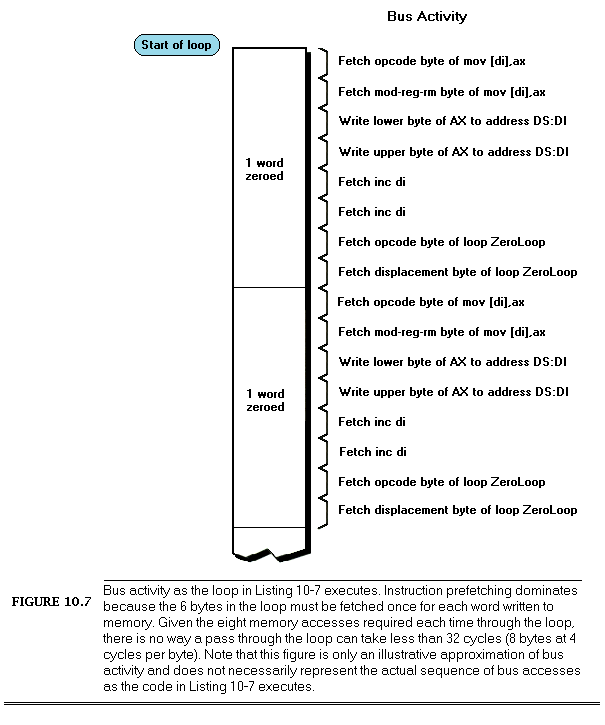
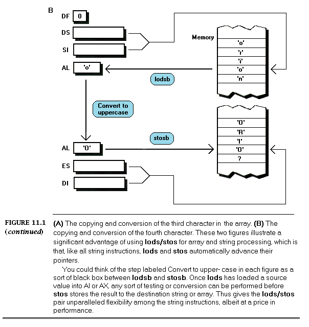
Of course, the function wasn’t two statements long in any meaningful sense; its true length would have to be measured in terms of all the machine-language instructions generated by those two C statements, as well as all the instructions executed by the function that printed the space character. By comparison with a single rep stosw instruction, which is the preferred way to clear the screen, this fellow’s screen clear function was undoubtedly very long indeed.
The programmer’s mistake was one of context. While his solution seemed optimal by the standards of the C environment he was programming in, it was considerably less ideal when applied to the PC, the environment in which the code actually had to run. While human-oriented abstractions such as high-level languages and system software have their virtues — most notably the ability to mask the complexities of processors and hardware — speed is not necessarily among those virtues.
We certainly don’t want to make the same mistake, so we’ll begin our search for knowledge by establishing a context for assembler programming, a usable framework within which to work for the remainder of this book. This is more challenging than it might at first glance seem, for the PC looks quite different to an assembler programmer — especially an assembler programmer interested in performance — than it does to a high-level language programmer. The difference is that a good assembler programmer sees the PC as it really is — hardware, software, warts and all — a perspective all too few programmers ever have the opportunity to enjoy.
From the Bottom Up
In this volume, we’re going to explore the knowledge needed for top-notch assembler programming. We’ll start at the bottom, with the hardware of the PC, and we’ll work our way up through the 8088’s registers, memory addressing capabilities, and instruction set. In Volume II of The Zen of Assembly Language, we’ll move on to putting that knowledge to work in the context of higher-level optimization, algorithm implementation, program design, and the like. We’re not going to spend time on topics, such as BIOS and DOS calls, that are well documented elsewhere, for we’ve a great deal of new ground to cover.
The next three chapters, which discuss the ways in which the hardware of the PC affects performance, are the foundation for everything that follows… and they also cover the most difficult material in The Zen of Assembly Language. Don’t worry if you don’t understand everything you read in the upcoming chapters; the same topics will come up again and again, from a variety of perspectives, throughout The Zen of Assembly Language. Read through Chapters 3 through 5 once now, absorbing as much as you can. After you’ve finished Volume I, come back to these chapters and read them again.
You’ll be amazed at how much sense they make — and at how much you’ve learned.
Let’s begin our explorations.
The Traditional Model
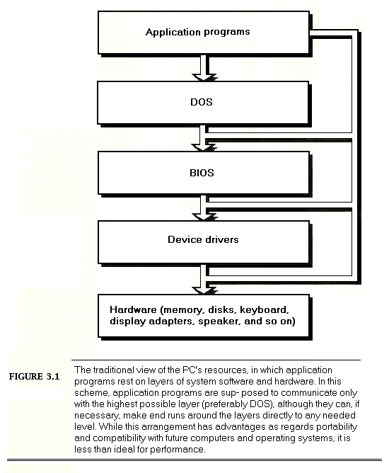
Figure 3.1 shows the traditional assembler programming model of the PC. In this model, the assembler program is separated from the hardware by layers of system software, such as DOS, the BIOS, and device drivers. Although this model recognizes that it is possible for assembler programs to make end runs around the layers to access any level of system software or the hardware directly, programs are supposed to request services from the highest level that can fulfill a given request (preferably DOS), thereby gaining hardware independence, which brings with it portability to other systems with different hardware but the same system software.
This model has many admirable qualities, and should be followed whenever possible. For example, because the DOS file system masks incompatibilities between the dozens of disk and disk controller models on the market, there’s generally nothing to be gained and much to be lost by programming a disk controller directly. Similarly, the BIOS sometimes hides differences between makes of keyboards, so keystrokes should not be taken directly from the hardware unless that’s absolutely necessary. Every assembler programmer should be thoroughly aware of the services provided by DOS and the BIOS, and should use them whenever they’re good enough for a given purpose.
A moment’s thought will show, however, that it’s not always desirable to follow the model of Figure 3.1. Disk-backup software programs the disk controller directly and sells handsomely, while keyboard macro programs and many pop-up programs read the keyboard directly. Part of your job as a programmer is knowing when to break the rules embodied by Figure 3.1, and breaking the rules is tempting because this model has major failings when it comes to performance.
One shortcoming of the model of Figure 3.1 is that DOS and the BIOS provide inadequate services in some areas, and no services at all in others. For instance, the half-hearted support DOS and the BIOS provide for serial communications is an insult to the potential of the PC’s communications hardware. Likewise, the graphics primitives offered by the BIOS are so slow and limited as to be virtually useless. While device drivers can extend DOS’s capabilities in some areas, many of the drivers are themselves embarrassingly slow and limited. As an example, the ANSI.SYS driver, which provides extended screen control in text mode, is so sluggish that a single screen update can take a second and more — quite a contrast with the instant screen updates most text editors and word processors offer.
When you use a system service, you’re accepting someone else’s solution to a problem; while it may be a good solution, you don’t know that unless you check. After all, you may well be a better programmer than the author of the system software, and you’re bound to be better attuned to your particular needs than he was. In short, you should know the system services well and use them fully, but you should also learn when it pays to replace them with your own code.
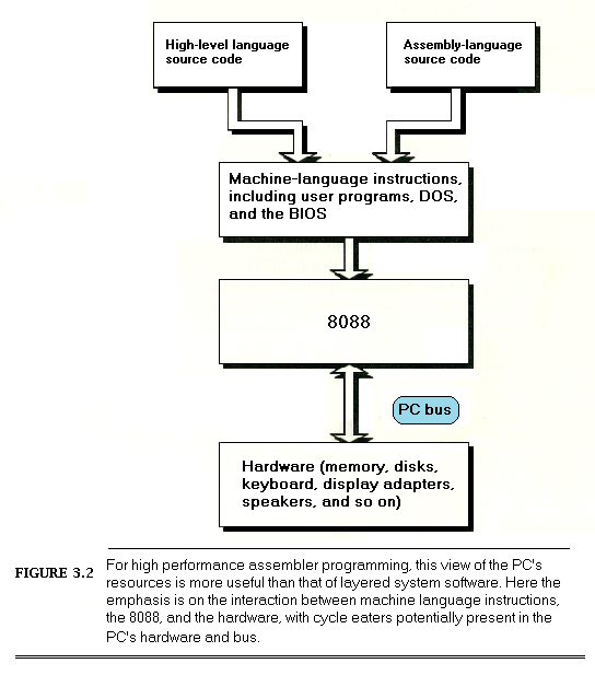
Cycle-Eaters
The second shortcoming of the model shown in Figure 3.1 is that it makes the hardware seem to be just another system resource, and a rather remote and uninteresting resource, at that. Nothing could be further from the truth! After all, in order to be useful programs must ultimately perform input from and output to the real world, and all input and output requires interaction with the hardware. True, DOS and the BIOS may handle much of your I/O, but DOS and the BIOS themselves are nothing more than assembly-language programs.
Also, programs access memory almost continuously, and memory is of course part of the PC’s hardware. It’s hard to write a code sequence of more than a few dozen instructions in which memory isn’t accessed at least once as either a stack operand or as a direct instruction operand. I/O ports are also accessed heavily in some applications. Every single memory and I/O access of any kind must interact with the hardware via the PC’s data bus.
It’s easy to think of the PC’s hardware and bus as being transparent to programs; hardware appears to be available on demand, while the bus seems to be nothing more than a path for data to take on the way to and from the hardware. Not so. While the PC bus is in fact generally transparent to programs, the many demands on the bus and the relatively low rate at which the bus, the 8088, and the PC’s memory together can support data transfers can have a significant effect on performance, as we’ll see shortly. Moreover, there are a number of memory and I/O devices for the PC that can’t access data fast enough to keep up with the PC bus; to compensate, they make the 8088 wait, sometimes for several cycles, while they catch up. Inevitably, program performance suffers from these characteristics of the hardware and bus.
For the remainder of this book, I’m going to refer to PC bus-and hardware-resident gremlins that affect code performance as “cycle-eaters.” There are cycle-eaters of many sorts, of which the prefetch queue and display adapter cycle-eaters are perhaps the best-known; 8-bit cards in ATs and dynamic RAM refresh are other examples. Cycle-eaters are undeniably difficult to pin down. Once you’ve identified and understood them, though, you’ll be among the elite few who can deal with the most powerful — and least understood — aspect of assembler programming.
Just how important are cycle-eaters? Well, thanks to the display adapter cycle-eater, the code in Listing 3-1, which accesses memory on an Enhanced Graphics Adapter (EGA), runs in 26.06 ms. That’s more than twice as long as the 11.24 ms of Listing 3-2, which is identical to Listing 3-1 except that it accesses normal system memory rather than display memory. That’s a difference in performance as great as that between an 8-MHz AT and a 16-MHz 80386 machine! Clearly, cycle-eaters cannot be ignored, and in the chapters to come we’ll spend considerable time tracking them down and devising ways to work around them.
Given cycle-eaters and our understanding of layered system software as simply another sort of code, the programming model shown in Figure 3.2 is more appropriate than that of Figure 3.1. All system and application software, whether generated from high-level or assembler source code, ultimately becomes a series of machine-language instructions for the 8088. The 8088 executes each of those instructions in turn, accessing memory and devices as needed by way of the PC bus. In this three-level structure, the 8088 provides software with a programming interface, and in turn rests on the PC’s hardware. Thanks to cycle-eaters, the PC’s hardware and bus emerge as important factors in performance.
The primary virtue of Figure 3.2 is that it moves us away from the comfortable, human-oriented perspective of Figure 3.1 and forces us to view program execution at a level closer to the true nature of the beast, as consisting of nothing more than the performance of a sequence of instructions that command the 8088 to perform actions; in some cases, those actions involve accessing memory and/or devices over the PC bus. From the software side, we can now see that all code consists of machine-language instructions in the end, so the distinction between high-level languages, system software, and assembler vanishes. From the hardware side, we can see that the 8088 is not the lowest level, and we can begin to appreciate the many ways in which hardware can directly affect code performance.
We need to see still more of the beast, however, and the place we’ll start is with the equivalence of code and data.
Code is Data
Code is nothing more than data that the 8088 interprets as instructions. The most obvious case of this is self-modifying code, where the 8088 treats its code as data in order to modify it, then executes those same bytes as instructions. There are many other examples, though — after all, what is a compiler but a program that transforms source code data into machine-language data? Both code and data consist of byte values stored in system memory; the only thing that differentiates code from any other sort of data is that the bytes that code is made of have a special meaning to the 8088, in that when fetched as instructions they instruct the 8088 to perform a series of (presumably related) actions. In other words, the meaning of byte values as code rather than data is strictly a matter of context.
Why is this important? It’s important because the 8088 is really two processors in one, and therein lies a tale.
Inside the 8088
Internally, the 8088 consists of two complementary processors: the Bus Interface Unit (BIU) and the Execution Unit (EU), as shown in Figure 3.3. The EU is what we normally think of as being a processor; it contains the flags, the general-purpose registers, and the Arithmetic Logic Unit (ALU), and executes instructions. In fact, the EU performs just about every function you could want from a processor — except one. The one thing the EU does not do is access memory or perform I/O. That’s the BIU’s job, so whenever the EU needs a memory or I/O access performed, it sends a request to the BIU, which carries out the access, transferring the data according to the EU’s specifications. The two units are capable of operating in parallel whenever they’ve got independent tasks to perform; put another way, the BIU can access memory or I/O at the same time that the EU is processing an instruction, so long as neither task is dependent on the other.
Each BIU memory access transfers 1 byte, since the 8088 has an 8-bit external data bus. The 8088 is designed so that each byte access takes a minimum of 4 cycles; given the PC’s 4.77-MHz processor clock, which results in a 209.5 ns cycle time, the 8088 supports a maximum data transfer rate of 1 byte/838 ns, or about 1.2 bytes/us. That’s an important number, and we’ll come back to it shortly.
The EU is capable of working with both 8-and 16-bit memory operands. Because the 8088 can only access memory a byte at a time, however, the BIU splits each of the EU’s 16-bit memory requests into a pair of 8-bit accesses. Since each 8-bit access requires a minimum of 4 cycles to execute, each 16-bit memory request takes at least 8 cycles, or 1.676 us. The instruction timings shown in Appendix A reflect the additional overhead of word memory accesses by indicating that 4 additional cycles per memory access should be added to the stated instruction execution times when word rather than byte memory operands are used.
The BIU contains all the memory-related logic of the 8088, including the segment registers and the Instruction Pointer, which points to the next instruction to be executed. Since code is just another sort of data, it makes sense that the Instruction Pointer resides in the BIU; after all, code bytes are read from memory just as data bytes are. In fact, the BIU takes on a bit of autonomy when it comes to fetching instructions. Whenever the EU isn’t making any memory or I/O requests, the BIU uses the otherwise idle time to fetch the bytes at the addresses immediately following the current instruction, on the reasonable theory that those addresses are likely to contain the next instructions that the EU will want. The BIU of the 8088 can store up to 4 potential instruction bytes in an internal prefetch queue, and other 8086-family processors can store more bytes still.
Instruction prefetching isn’t always advantageous. In particular, if the instruction the 8088 is currently executing results in a branch of any sort, the bytes in the instruction queue are of no value, since they are the bytes the 8088 would have executed had the branch not been performed. As a result, all the 8088 can do when a branch occurs is discard all the bytes in the prefetch queue and start fetching instructions all over again.
Nonetheless, the prefetching scheme often allows the BIU to have the next instruction byte waiting when the EU comes calling for it. Bear in mind that the EU and BIU can operate at the same time; it’s only when the EU is waiting for the BIU to finish a memory or I/O operation for it that the EU is held up. The virtue of the 8088’s internal architecture, then, is that the EU can increase its effective processing time because the BIU often coprocesses with it. Since instruction fetches occur in a constant stream — usually much more frequently than memory operand accesses — instruction prefetching is the most important sort of coprocessing the BIU performs.
It’s worth noting at this point that the execution time specified by Intel for any given instruction running on the 8088 (as shown in Appendix A) assumes that the BIU has already prefetched that instruction and has it ready and waiting for the EU. If the next instruction is not waiting for the EU when the EU completes the current instruction, at least some of the time required to fetch the next instruction must be added to its specified execution time in order to arrive at the actual execution time.
The degree to which the EU and BIU can coprocess during instruction fetching is not uniform for all types of code; in fact, it varies considerably depending on the mix of instructions being executed. Multiplication and division instructions are ideal for coprocessing, since the BIU can prefetch until the queue is full while these very long instructions execute. Among other instructions, oddly enough, it is code that performs many memory accesses that allows the EU and BIU to coprocess most effectively, because the 8088 is relatively slow at executing instructions that access memory (as we’ll see in Chapter 7). While a single memory-accessing instruction is being executed, the BIU can often prefetch 1 to 4 instruction bytes (depending on the instruction being performed) and still leave time for the memory access to occur. Execution of a memory-accessing instruction and prefetching of the next instruction can generally proceed simultaneously, so such instructions often run at close to full speed.
Ironically, code that primarily performs register-only operations and rarely accesses memory affords little opportunity for prefetching, because register-only instructions execute so rapidly that the BIU can’t fetch instruction bytes nearly as rapidly as the EU can execute them. To see why this is so, recall that the 8088 can fetch 1 byte every 4 cycles, or 0.838 us. The shr instruction is 2 bytes long, so it takes 1.676 us to fetch each shr instruction. However, the EU can execute a shr in just 2 cycles, or 0.419 us, four times as rapidly as the BIU can fetch the same instruction.
The instruction queue can be depleted quickly by register-only instructions. Given enough such instructions in a row, the overall time required to complete a series of register-only instructions is determined almost entirely by the time required to fetch the instructions from memory. This is precisely the respect in which Figure 3.2 fails us; because of the prefetch queue, the instructions the 8088 executes must be viewed as data, stored along with other program data and accessed through the same PC bus and BIU, as shown in Figure 3.4. Seen in this light, it becomes apparent that instruction fetches are subject to the same cycle-eaters as are memory operand accesses. What’s more, the BIU emerges as potentially the greatest cycle-eater of all, as code and data bytes struggle to get through the BIU fast enough to keep the EU busy, a phenomenon I’ll refer to as the prefetch queue cycle-eater from now on. As we will see, designing code to work around the prefetch queue cycle-eater and keep the EU busy is a difficult but rewarding task.
Stepchild of the 8086
You might justifiably wonder why Intel would design a processor with an EU that can execute instructions faster than the BIU can possibly fetch them. The answer is that they didn’t; they designed the 8086, then created the 8088 as a poor man’s 8086.
The 8086 is completely software compatible with the 8088, and in fact differs from the 8088 in only one important respect, the width of the external data bus (the bus that goes off-chip to memory and peripherals); where the 8088 has an 8-bit wide external data bus, the 8086 has a 16-bit wide bus. (The 8086 also has a 6-rather than 4-byte prefetch queue, which gives it a bit of an advantage in keeping the EU busy.) Both the 8086 and 8088 have 16-bit EUs and 16-bit internal data buses, but while the 8086’s BIU can fulfill most 16-bit memory requests with a single memory access, the 8088’s BIU must convert 16-bit memory requests into 8-bit memory accesses. Figure 3.5, which charts internal and external data bus sizes for processors from the 8080 through the 80386, shows that the 8088 is something of an aberration in that it is the only widely-used processor in the 8086 family with mismatched internal and external data bus sizes. (The 80386SX, which may well become a successful low-cost substitute for the 80386, also has mismatched internal and external bus sizes, and as a result suffers from many of the same performance constraints as does the 8088.)
There is a significant price to be paid for the 8088’s mismatched bus sizes. Why? Well, the 8086 was designed to support efficient and balanced memory access, with the external data bus in general in use as much as possible without that bus becoming a bottleneck. In other words, the 16-bit external data bus of the 8086 was designed to provide a memory access rate roughly equal to the processing rate of which the 16-bit EU is capable. While the 8088 offers the same internal 16-bit architecture as the 8086, the 8-bit external data bus of the 8088 can provide at best only half the memory access rate of the 8086, so the balance of the 8086 is lost.
The obvious effect of the 8088’s mismatched bus sizes is that accesses to word-sized memory operands take 4 cycles longer on an 8088 than on an 8086, but that’s actually not the most significant fallout of the 8-bit external data bus. More significant is the prefetch queue cycle-eater, which is the result of the inability of the 8088’s BIU to fetch instructions and operands over the 8-bit external data bus as fast as the 16-bit EU can process them, thereby limiting the performance of the 8088’s fastest instructions. By contrast, the 8086, for which the EU was originally designed, has little trouble keeping the EU supplied with instructions and data; the 8086’s BIU fetches 2 instruction bytes in the same time it takes the 8088 to fetch a single byte, making the 8086 instruction fetching rate twice that of the 8088.
How significant is the performance impact of the 8088’s 8-bit external data bus? While normal code is estimated to run only about one-third faster on an 8086 than on an 8088, high-performance 8086 code can — as we’ve already seen — run as much as four times more slowly on an 8088 once the prefetch queue empties, because code performance is limited by the rate at which the BIU can transfer data a byte at a time. In the case where both the 8088 and 8086 prefetch queues are emptied, the 8086 runs fast assembler code only twice as fast as the 8088, but the 8086 has a bigger prefetch queue than the 8088 and fetches instructions twice as fast, so the 8086 queue empties much more slowly — and in any case, twice as fast is nothing to sniff at.
In short, the 8086 is just like the 8088 — except that it’s somewhere between 0% and 300% faster, depending on what code happens to be executing, with a typical performance advantage of somewhere between 33% and 100% for high-performance assembler code.
Why then does the 8088 exist, and why has it become so popular? An 8-bit-bus version of the 8086 (that is, the 8088) was desirable in the late 1970s because at that time it was significantly more expensive to build a computer with a 16-bit data bus than with an 8-bit data bus. The 8088 allowed the construction of low-cost, low-performance computers that would run 8086 software, albeit more slowly. As it turned out, the cost advantage of an 8-bit memory data bus quickly became relatively insignificant, and the 8088 might have vanished into obscurity had IBM not selected it for the PC; then we might never have had the pleasure of wrestling with the prefetch queue cycle-eater. However, IBM did select the 8088 for the PC, and the rest is history.
Incidentally, an imbalance between processing speed and memory access speed remains a factor today with the 80286-based IBM AT and with many 80386-based computers. The memory in those computers often does not run at the speeds the processors are capable of, and assembler code encounters the same sorts of performance losses when running on those computers as it does on the 8088. We’ll return to that topic in Chapter 15.
Which Model to Use?
Each of the three programming models I’ve presented offers a useful perspective on assembler programming for the PC. However, it is the model shown in Figure 3.4 that best reflects the true nature of the 8088; consequently, that model is the most useful of the three for tapping the unique potential of assembler. While we’ll use elements of all three models in The Zen of Assembly Language, we’ll concentrate on the perspective of Figure 3.4 as we explore high-performance assembler programming.
Keep the following concepts in mind as you read on:
All code is machine language in the end: don’t assume that anyone else’s code, even system software, is best suited for your needs.
1.2 bytes/us: at its best, the 8088’s BIU can transfer data no faster than this.
The 8088 is not the lowest level: know how the PC’s hardware and bus affect memory access speed.
Code is data: when the BIU and the PC’s hardware and bus affect memory access speed, they affect code fetching as well as data access, since code is just another sort of data in system memory.
Short and simple as the above list may seem, in it you will find every one of the concepts that form the foundation of the Zen of assembler — and with them the key to high-performance code.
Chapter 4: Things Mother Never Told You: Under the Programming Interface
Over the last few chapters we’ve seen that programming has many levels, ranging from the familiar (high-level languages, DOS calls, and the like) to the esoteric (cycle-eaters). In this chapter we’re going to jump right in at the lowest level by examining the cycle-eaters that live beneath the programming interface.
Why start at the lowest level? Simply because cycle-eaters affect the performance of all assembler code, and yet are almost unknown to most programmers. A full understanding of virtually everything else we’ll discuss in The Zen of Assembly Language requires an understanding of cycle-eaters and their implications. That’s no simple task, and in fact it is in precisely that area that most books and articles about assembler programming fall short.
Nearly all literature on assembler programming discusses only the programming interface: the instruction set, the registers, the flags, and the BIOS and DOS calls. Those topics cover the functionality of assembler programs most thoroughly — but it’s performance above all else that we’re after. No one ever tells you about the raw stuff of performance, which lies beneath the programming interface, in the dimly-seen realm-populated by instruction prefetching, dynamic RAM refresh, and wait states — where software meets hardware. This area is the domain of hardware engineers, and is almost never discussed as it relates to code performance. And yet it is only by understanding the mechanisms operating at this level that we can fully understand and properly improve the performance of our code.
Which brings us to cycle-eaters.
Cycle-Eaters Revisited
You’ll recall that cycle-eaters are gremlins that live on the bus or in peripherals, slowing the performance of 8088 code so that it doesn’t execute at full speed. Because cycle-eaters live outside the Execution Unit of the 8088, they can only affect the 8088 when the 8088 performs a bus access (a memory or I/O read or write). Internally, the 8088 is a 16-bit processor, capable of running at full speed at all times — unless external data is required. External data must traverse the 8088’s external data bus and the PC’s data bus 1 byte at a time to and from peripherals, with cycle-eaters lurking along every step of the way. What’s more, external data includes not only memory operands but also instruction bytes, so even instructions with no memory operands can suffer from cycle-eaters. Since some of the 8088’s fastest instructions are register-only instructions, that’s important indeed.
The major cycle-eaters are:
The 8088’s 8-bit external data bus.
The prefetch queue.
Dynamic RAM refresh.
Wait states, notably display memory wait states and, in the AT and 80386 computers, system memory wait states.
The locations of these cycle-eaters in the PC are shown in Figure 4.1. We’ll cover each of the cycle-eaters in turn in this chapter. The material won’t be easy, since cycle-eaters are among the most subtle aspects of assembler programming. By the same token, however, this will be one of the most important and rewarding chapters in this book. Don’t worry if you don’t catch everything in this chapter, but do read it all even if the going gets a bit tough. Cycle-eaters play a key role in later chapters, so some familiarity with them is highly desirable. Then, too, those later chapters illustrate cycle-eaters in action, which should help clear up any aspects of cycle-eaters about which you’re uncertain.
The 8-Bit Bus Cycle-Eater
Look! Down on the motherboard! It’s a 16-bit processor! It’s an 8-bit processor! It’s…
…an 8088!
Fans of the 8088 call it a 16-bit processor. Fans of other 16-bit processors call the 8088 an 8-bit processor. Unbiased as we are, we know that the truth of the matter is that the 8088 is a 16-bit processor that often performs like an 8-bit processor.
As we saw in Chapter 3, the 8088 is internally a full 16-bit processor, equivalent to an 8086. In terms of the instruction set, the 8088 is clearly a 16-bit processor, capable of performing any given 16-bit operation — addition, subtraction, even multiplication or division — with a single instruction. Externally, however, the 8088 is unequivocally an 8-bit processor, since the external data bus is only 8 bits wide. In other words, the programming interface is 16 bits wide, but the hardware interface is only 8 bits wide, as shown in Figure 4.2. The result of this mismatch is simple: word-sized data can be transferred between the 8088 and memory or peripherals at only one-half the maximum rate of the 8086, which is to say one-half the maximum rate for which the Execution Unit of the 8088 was designed.
As shown in Figure 4.1, the 8-bit bus cycle-eater lies squarely on the 8088’s external data bus. Technically, it might be more accurate to place this cycle-eater in the Bus Interface Unit, which breaks 16-bit memory accesses into paired 8-bit accesses, but it is really the limited width of the external data bus that constricts data flow into and out of the 8088. True, the PC’s bus is also only 8 bits wide, but that’s just to match the 8088’s 8-bit bus; even if the PC’s bus were 16 bits wide, data could still pass into and out of the 8088 only 1 byte at a time.
Each bus access by the 8088 takes 4 clock cycles, or 0.838 us in the PC, and transfers 1 byte. That means that the maximum rate at which data can be transferred into and out of the 8088 is 1 byte every 0.838 us. While 8086 bus accesses also take 4 clock cycles, each 8086 bus access can transfer either 1 byte or 1 word, for a maximum transfer rate of 1 word every 0.838 us. Consequently, for word-sized memory accesses the 8086 has an effective transfer rate of 1 byte every 0.419 us. By contrast, every word-sized access on the 8088 requires two 4-cycle-long bus accesses, one for the high byte of the word and one for the low byte of the word. As a result, the 8088 has an effective transfer rate for word-sized memory accesses of just 1 word every 1.676 us — and that, in a nutshell, is the 8-bit bus cycle-eater.
The Impact of the 8-Bit Bus Cycle-Eater
One obvious effect of the 8-bit bus cycle-eater is that word-sized accesses to memory operands on the 8088 take 4 cycles longer than byte-sized accesses. That’s why the instruction timings in Appendix A indicate that for code running on an 8088 an additional 4 cycles are required for every word-sized access to a memory operand. For instance:
movax,wordptr [MemVar]
takes 4 cycles longer to read the word at address MemVar than:
moval,byteptr [MemVar]
takes to read the byte at address MemVar. (Actually, the difference between the two isn’t very likely to be exactly 4 cycles, for reasons that will become clear when we discuss the prefetch queue and dynamic RAM refresh cycle-eaters later in this chapter.)
What’s more, in some cases one instruction can perform multiple word-sized accesses, incurring that 4-cycle penalty on each access. For example, adding a value to a word-sized memory variable requires 2 word-sized accesses — one to read the destination operand from memory prior to adding to it, and one to write the result of the addition back to the destination operand — and thus incurs not one but two 4-cycle penalties. As a result:
addwordptr [MemVar],ax
takes about 8 cycles longer to execute than:
addbyteptr [MemVar],al
String instructions can suffer from the 8-bit bus cycle-eater to a greater extent than other instructions. Believe it or not, a single rep movsw instruction can lose as much as:
524,280 cycles = 131,070 word-sized memory accesses x 4 cycles
to the 8-bit bus cycle-eater! In other words, one 8088 instruction (admittedly, an instruction that does a great deal) can take over one-tenth of a second longer on an 8088 than on an 8086, simply because of the 8-bit bus. One-tenth of a second! That’s a phenomenally long time in computer terms; in one-tenth of a second, the 8088 can perform more than 50,000 additions and subtractions.
The upshot of all this is simply that the 8088 can transfer word-sized data to and from memory at only half the speed of the 8086, which inevitably causes performance problems when coupled with an Execution Unit that can process word-sized data every bit as fast as an 8086. These problems show up with any code that uses word-sized memory operands. More ominously, as we will see shortly, the 8-bit bus cycle-eater can cause performance problems with other sorts of code as well.
What to Do About the 8-Bit Bus Cycle-Eater?
The obvious implication of the 8-bit bus cycle-eater is that byte-sized memory variables should be used whenever possible. After all, the 8088 performs byte-sized memory accesses just as quickly as the 8086. For instance, Listing 4-1, which uses a byte-sized memory variable as a loop counter, runs in 10.03 us per loop. That’s 20% faster than the 12.05 us per loop execution time of Listing 4-2, which uses a word-sized counter. Why the difference in execution times? Simply because each word-sized dec performs 4 byte-sized memory accesses (2 to read the word-sized operand and 2 to write the result back to memory), while each byte-sized dec performs only 2 byte-sized memory accesses in all.
I’d like to make a brief aside concerning code optimization in the listings in this book. Throughout this book I’ve modeled the sample code after working code so that the timing results are applicable to real-world programming. In Listings 4-1 and 4-2, for instance, I could have shown a still greater advantage for byte-sized operands simply by performing 1000 dec instructions in a row, with no branching at all. However, dec instructions don’t exist in a vacuum, so in the listings I used code that both decremented the counter and tested the result. The difference is that between decrementing a memory location (simply an instruction) and using a loop counter (a functional instruction sequence). If you come across code in The Zen of Assembly Language that seems less than optimal, my desire to provide code that’s relevant to real programming problems may be the reason. On the other hand, optimal code is an elusive thing indeed; by no means should you assume that the code in this book is ideal! Examine it, question it, and improve upon it, for an inquisitive, skeptical mind is an important part of the Zen of assembler.
Back to the 8-bit bus cycle-eater. As I’ve said, you should strive to use byte-sized memory variables whenever possible. That does not mean that you should use 2 byte-sized memory accesses to manipulate a word-sized memory variable in preference to 1 word-sized memory access, as, for instance, with:
movdl,byteptr [MemVar]
movdh,byteptr [MemVar+1]
versus:
movdx,wordptr [MemVar]
Recall that every access to a memory byte takes at least 4 cycles; that limitation is built right into the 8088. The 8088 is also built so that the second byte-sized memory access to a 16-bit memory variable takes just those 4 cycles and no more. There’s no way you can manipulate the second byte of a word-sized memory variable faster with a second separate byte-sized instruction in less than 4 cycles. As a matter of fact, you’re bound to access that second byte much more slowly with a separate instruction, thanks to the overhead of instruction fetching and execution, address calculation, and the like.
For example, consider Listing 4-3, which performs 1000 word-sized reads from memory. This code runs in 3.77 us per word read. That’s 45% faster than the 5.49 us per word read of Listing 4-4, which reads the same 1000 words as Listing 4-3 but does so with 2000 byte-sized reads. Both listings perform exactly the same number of memory accesses — 2000 accesses, each byte-sized, as all 8088 memory accesses must be. (Remember that the Bus Interface Unit must perform two byte-sized memory accesses in order to handle a word-sized memory operand.) However, Listing 4-3 is considerably faster because it expends only 4 additional cycles to read the second byte of each word, while Listing 4-4 performs a second lodsb, requiring 13 cycles, to read the second byte of each word.
In short, if you must perform a 16-bit memory access, let the 8088 break the access into two byte-sized accesses for you. The 8088 is more efficient at that task than your code can possibly be.
Chapter 9 has further examples of ways in which you can take advantage of the 8088’s relative speed at handling the second byte of a word-sized memory operand to improve your code. However, that advantage only exists relative to the time taken to access 2 byte-sized memory operands; you’re still better off using single byte-sized memory accesses rather than word-sized accesses whenever possible. Word-sized variables should be stored in registers to the greatest feasible extent, since registers are inside the 8088, where 16-bit operations are just as fast as 8-bit operations because the 8-bit cycle-eater can’t get at them. In fact, it’s a good idea to keep as many variables of all sorts in registers as you can. Instructions with register-only operands execute very rapidly, partially because they avoid both the time-consuming memory accesses and the lengthy address calculations associated with memory operands.
There is yet another reason why register operands are preferable to memory operands, and it’s an unexpected effect of the 8-bit bus cycle-eater. Instructions with only register operands tend to be shorter (in terms of bytes) than instructions with memory operands, and when it comes to performance, shorter is usually better. In order to explain why that is true and how it relates to the 8-bit bus cycle-eater, I must diverge for a moment.
For the last few pages, you may well have been thinking that the 8-bit bus cycle-eater, while a nuisance, doesn’t seem particularly subtle or difficult to quantify. After all, Appendix A tells us exactly how many cycles each instruction loses to the 8-bit bus cycle-eater, doesn’t it?
Yes and no. It’s true that in general we know approximately how much longer a given instruction will take to execute with a word-sized memory operand than with a byte-sized operand, although the dynamic RAM refresh and wait state cycle-eaters can raise the cost of the 8-bit bus cycle-eater considerably, as we’ll see later in this chapter. However, all word-sized memory accesses lose 4 cycles to the 8-bit bus cycle-eater, and there’s one sort of word-sized memory access we haven’t discussed yet: instruction fetching. The ugliest manifestation of the 8-bit bus cycle-eater is in fact the prefetch queue cycle-eater.
The Prefetch Queue Cycle-Eater
Simply put, here’s the prefetch queue cycle-eater: the 8088’s 8-bit external data bus keeps the Bus Interface Unit from fetching instruction bytes as fast as the 16-bit Execution Unit can execute them, so the Execution Unit often lies idle while waiting for the next instruction byte to be fetched.
Exactly why does this happen? Recall that the 8088 is an 8086 internally, but accesses word-sized memory data at only one-half the maximum rate of the 8086 due to the 8088’s 8-bit external data bus. Unfortunately, instructions are among the word-sized data the 8086 fetches, meaning that the 8088 can fetch instructions at only one-half the speed of the 8086. On the other hand, the 8086-equivalent Execution Unit of the 8088 can execute instructions every bit as fast as the 8086. The net result is that the Execution Unit burns up instruction bytes much faster than the Bus Interface Unit can fetch them, and ends up idling while waiting for instructions bytes to arrive.
The BIU can fetch instruction bytes at a maximum rate of one byte every 4 cycles-and that 4-cycle per instruction byte rate is the ultimate limit on overall instruction execution time, regardless of EU speed. While the EU may execute a given instruction that’s already in the prefetch queue in less than 4 cycles per byte, over time the EU can’t execute instructions any faster than they can arrive-and they can’t arrive faster than 1 byte every 4 cycles.
Clearly, then, the prefetch queue cycle-eater is nothing more than one aspect of the 8-bit bus cycle-eater. 8088 code often runs at less than the Execution Unit’s maximum speed because the 8-bit data bus can’t keep up with the demand for instruction bytes. That’s straightforward enough-so why all the fuss about the prefetch queue cycle-eater?
What makes the prefetch queue cycle-eater tricky is that it’s undocumented and unpredictable. That is, with a word-sized memory access, such as:
mov [bx],ax
it’s well-documented that an extra 4 cycles will always be required to write the upper byte of AX to memory. Not so with the prefetch queue. For instance, the instructions:
shrax,1shrax,1shrax,1shrax,1shrax,1
should execute in 10 cycles, according to the specifications in Appendix A, since each shr takes 2 cycles to execute. Those specifications contain Intel’s official instruction execution times, but in this case-and in many others-the specifications are drastically wrong. Why? Because they describe execution time once an instruction reaches the prefetch queue. They say nothing about whether a given instruction will be in the prefetch queue when it’s time for that instruction to run, or how long it will take that instruction to reach the prefetch queue if it’s not there already. Thanks to the low performance of the 8088’s external data bus, that’s a glaring omission -but, alas, an unavoidable one. Let’s look at why the official execution times are wrong, and why that can’t be helped.
Official Execution Times are Only Part of the Story
The sequence of 5 shr instructions in the last example is 10 bytes long. That means that it can never execute in less than 24 cycles even if the 4-byte prefetch queue is full when it starts, since 6 instruction bytes would still remain to be fetched, at 4 cycles per fetch. If the prefetch queue is empty at the start, the sequence could take 40 cycles. In short, thanks to instruction fetching the code won’t run at its documented speed, and could take up to 4 times as long as it is supposed to.
Why does Intel document Execution Unit execution time rather than overall instruction execution time, which includes both instruction fetch time and Execution Unit execution time? As described in Chapter 3, instruction fetching isn’t performed as part of instruction execution by the Execution Unit, but instead is carried on in parallel by the Bus Interface Unit whenever the external data bus isn’t in use or whenever the EU runs out of instruction bytes to execute. Sometimes the BIU is able to use spare bus cycles to prefetch instruction bytes before the EU needs them, so instruction fetching takes no time at all, practically speaking. At other times the EU executes instructions faster than the BIU can fetch them and instruction fetching becomes a significant part of overall execution time. As a result, the effective fetch time for a given instruction varies greatly depending on the code mix preceding that instruction. Similarly, the state in which a given instruction leaves the prefetch queue affects the overall execution time of the following instructions.
In other words, while the execution time for a given instruction is constant, the fetch time for that instruction depends on the context in which the instruction is executing -the amount of prefetching the preceding instructions allowed -and can vary from a full 4 cycles per instruction byte to no time at all. As we’ll see later, other cycle-eaters, such as DRAM refresh and display memory wait states, can cause prefetching variations even during different executions of the same code sequence. Given that, it’s meaningless to talk about the prefetch time of a given instruction except in the context of a specific code sequence.
So now you know why the official instruction execution times are often wrong, and why Intel can’t provide better specifications. You also know now why it is that you must time your code if you want to know how fast it really is.
There is No Such Beast as a True Instruction Execution Time
The effect of the code preceding an instruction on the execution time of that instruction makes the Zen timer trickier to use than you might expect, and complicates the interpretation of the results reported by the Zen timer. For one thing, the Zen timer is best used to time code sequences that are more than a few instructions long; below 10 us or so, prefetch queue effects and the limited resolution of the clock driving the timer can cause problems.
Some slight prefetch queue-induced inaccuracy usually exists even when the Zen timer is used to time longer code sequences, since the calls to the Zen timer usually alter the code’s prefetch queue from its normal state. (As we’ll see in Chapter 12, branches — jumps, calls, returns and the like — empty the prefetch queue.) Ideally, the Zen timer is used to measure the performance of an entire subroutine, so the prefetch queue effects of the branches at the start and end of the subroutine are similar to the effects of the calls to the Zen timer when you’re measuring the subroutine’s performance.
Another way in which the prefetch queue cycle-eater complicates the use of the Zen timer involves the practice of timing the performance of a few instructions over and over. I’ll often repeat one or two instructions 100 or 1000 times in a row in listings in this book in order to get timing intervals that are long enough to provide reliable measurements. However, as we just learned, the actual performance of any 8088 instruction depends on the code mix preceding any given use of that instruction, which in turns affects the state of the prefetch queue when the instruction starts executing. Alas, the execution time of an instruction preceded by dozens of identical instructions reflects just one of many possible prefetch states (and not a very likely state at that), and some of the other prefetch states may well produce distinctly different results.
For example, consider the code in Listings 4-5 and 4-6. Listing 4-5 shows our familiar shr case. Here, because the prefetch queue is always empty, execution time should work out to about 4 cycles per byte, or 8 cycles per shr, as shown in Figure 4.3. (Figure 4.3 illustrates the relationship between instruction fetching and execution in a simplified way, and is not intended to show the exact timings of 8088 operations.) That’s quite a contrast to the official 2-cycle execution time of shr. In fact, the Zen timer reports that Listing 4-5 executes in 1.81 us per byte, or slightly more than 4 cycles per byte. (The extra time is the result of the dynamic RAM refresh cycle-eater, which we’ll discuss shortly.) Going strictly by Listing 4-5, we would conclude that the “true” execution time of shr is 8.64 cycles.
Now let’s examine Listing 4-6. Here each shr follows a mul instruction. Since mul instructions take so long to execute that the prefetch queue is always full when they finish, each shr should be ready and waiting in the prefetch queue when the preceding mul ends. As a result, we’d expect that each shr would execute in 2 cycles; together with the 118 cycle execution time of multiplying 0 times 0, the total execution time should come to 120 cycles per shr/mul pair, as shown in Figure 4.4. And, by God, when we run Listing 4-6 we get an execution time of 25.14 us per shr/mul pair, or exactly 120 cycles! According to these results, the “true” execution time of shr would seem to be 2 cycles, quite a change from the conclusion we drew from Listing 4-5.
The key point is this: we’ve seen one code sequence in which shr took 8-plus cycles to execute, and another in which it took only 2 cycles. Are we talking about two different forms of shr here? Of course not — the difference is purely a reflection of the differing states in which the preceding code left the prefetch queue. In Listing 4-5, each shr after the first few follows a slew of other shr instructions which have sucked the prefetch queue dry, so overall performance reflects instruction fetch time. By contrast, each shr in Listing 4-6 follows a mul instruction which leaves the prefetch queue full, so overall performance reflects Execution Unit execution time.
Clearly, either instruction fetch time or Execution Unit execution time — or even a mix of the two, if an instruction is partially prefetched — can determine code performance. Some people operate under a rule of thumb by which they assume that the execution time of each instruction is 4 cycles times the number of bytes in the instruction. While that’s often true for register-only code, it frequently doesn’t hold for code that accesses memory. For one thing, the rule should be 4 cycles times the number of memory accesses, not instruction bytes, since all accesses take 4 cycles. For another, memory-accessing instructions often have slower Execution Unit execution times than the 4 cycles per memory access rule would dictate, because the 8088 isn’t very fast at calculating memory addresses, as we’ll see in Chapter 7. Also, the 4 cycles per instruction byte rule isn’t true for register-only instructions that are already in the prefetch queue when the preceding instruction ends.
The truth is that it never hurts performance to reduce either the cycle count or the byte count of a given bit of code, but there’s no guarantee that one or the other will improve performance either. For example, consider Listing 4-7, which consists of a series of 4-cycle, 2-byte moval,0 instructions, and which executes at the rate of 1.81 us per instruction. Now consider Listing 4-8, which replaces the 4-cycle moval,0 with the 3-cycle (but still 2-byte) subal,al. Despite its 1-cycle-per-instruction advantage, Listing 4-8 runs at exactly the same speed as Listing 4-7. The reason: both instructions are 2 bytes long, and in both cases it is the 8-cycle instruction fetch time, not the 3-or 4-cycle Execution Unit execution time, that limits performance.
As you can see, it’s easy to be drawn into thinking you’re saving cycles when you’re not. You can only improve the performance of a specific bit of code by reducing the factor - either instruction fetch time or execution time, or sometimes a mix of the two — that’s limiting the performance of that code.
In case you missed it in all the excitement, the variability of prefetching means that our method of testing performance by executing 1000 instructions in a row by no means produces “true” instruction execution times, any more than the official execution times in Appendix A are “true” times. The fact of the matter is that a given instruction takes at least as long to execute as the time given for it in Appendix A, but may take as much as 4 cycles per byte longer, depending on the state of the prefetch queue when the preceding instruction ends. The only true execution time for an instruction is a time measured in a certain context, and that time is meaningful only in that context.
Look at it this way. We’ve firmly established that there’s no number you can attach to a given instruction that’s always that instruction’s true execution time. In fact, as we’ll see in the rest of this chapter and in the next, there are other cycle-eaters that can work with the prefetch queue cycle-eater to cause the execution time of an instruction to vary to an even greater extent than we’ve seen so far. That’s okay, though, because the execution time of a single instruction is not what we’re really after.
What we really want is to know how long useful working code takes to run, not how long a single instruction takes, and the Zen timer gives us the tool we need to gather that information. Granted, it would be easier if we could just add up neatly documented instruction execution times — but that’s not going to happen. Without actually measuring the performance of a given code sequence, you simply don’t know how fast it is. For crying out loud, even the people who designed the 8088 at Intel couldn’t tell you exactly how quickly a given 8088 code sequence executes on the PC just by looking at it! Get used to the idea that execution times are only meaningful in context, learn the rules of thumb in this book, and use the Zen timer to measure your code.
Approximating Overall Execution Times
Don’t think that because overall instruction execution time is determined by both instruction fetch time and Execution Unit execution time, the two times should be added together when estimating performance. For example, practically speaking, each shr in Listing 4-5 does not take 8 cycles of instruction fetch time plus 2 cycles of Execution Unit execution time to execute. Figure 4.3 shows that while a given shr is executing, the fetch of the next shris starting, and since the two operations are overlapped for 2 cycles, there’s no sense in charging the time to both instructions. You could think of the extra instruction fetch time for shr in Listing 4-5 as being 6 cycles, which yields an overall execution time of 8 cycles when added to the 2 cycles of Execution Unit execution time.
Alternatively, you could think of each shr in Listing 4-5 as taking 8 cycles to fetch, and then executing in effectively 0 cycles while the next shr is being fetched. Whichever perspective you prefer is fine. The important point is that the time during which the execution of one instruction and the fetching of the next instruction overlap should only be counted toward the overall execution time of one of the instructions. For all intents and purposes, one of the two instructions runs at no performance cost whatsoever while the overlap exists.
As a working definition, we’ll consider the execution time of a given instruction in a particular context to start when the first byte of the instruction is sent to the Execution Unit and end when the first byte of the next instruction is sent to the EU. We’ll discuss this further in Chapter 5.
What to Do About the Prefetch Queue Cycle-Eater?
Reducing the impact of the prefetch queue cycle-eater is one of the overriding principles of high-performance assembler code. How can you do this? One effective technique is to minimize access to memory operands, since such accesses compete with instruction fetching for precious memory accesses. You can also greatly reduce instruction fetch time simply by your choice of instructions: keep your instructions short. Less time is required to fetch instructions that are 1 or 2 bytes long than instructions that are 5 or 6 bytes long. Reduced instruction fetching lowers minimum execution time (minimum execution time is 4 cycles times the number of instruction bytes) and often leads to faster overall execution.
While short instructions minimize overall prefetch time, they ironically actually often suffer relatively more from the prefetch queue bottleneck than do long instructions. Short instructions generally have such fast execution times that they drain the prefetch queue despite their small size. For example, consider the shr of Listing 4-5, which runs at only 25% of its Execution Unit execution time even though it’s only 2 bytes long, thanks to the prefetch queue bottleneck. Short instructions are nonetheless generally faster than long instructions, thanks to the combination of fewer instruction bytes and faster Execution Unit execution times, and should be used as much as possible — just don’t expect them to run at their documented speeds.
More than anything, the above rules mean using the registers as heavily as possible, both because register-only instructions are short and because they don’t perform memory accesses to read or write operands. (Using the registers is a topic we’ll return to repeatedly in The Zen of Assembly Language.) However, using the registers is a rule of thumb, not a commandment. In some circumstances, it may actually be faster to access memory. (The look-up table technique, which we’ll encounter in Chapter 7, is one such case.) What’s more, the performance of the prefetch queue (and hence the performance of each instruction) differs from one code sequence to the next, and can even differ during different executions of the same code sequence.
All in all, writing good assembler code is as much an art as a science. As a result, you should follow the rules of thumb described in The Zen of Assembly Language — and then time your code to see how fast it really is. You should experiment freely, but always remember that actual, measured performance is the bottom line.
The prefetch queue cycle-eater looms over the performance of all 8088 code. We’ll encounter it again and again in this book, and in every case it will make our code slower than it would otherwise be. An understanding of the prefetch queue cycle-eater provides deep insight into what makes some 8088 code much faster than other, seemingly similar 8088 code, and is a key to good assembler programming. You’ll never conquer this cycle-eater, but with experience and the Zen timer you can surely gain the advantage.
Holding Up the 8088
Over the last two chapters I’ve taken you further and further into the depths of the PC, telling you again and again that you must understand the computer at the lowest possible level in order to write good code. At this point, you may well wonder, “Have we gotten low enough?”
Not quite yet. The 8-bit bus and prefetch queue cycle-eaters are low-level indeed, but we’ve one level yet to go. Dynamic RAM refresh and wait states — our next topics — together form the lowest level at which the hardware of the PC affects code performance. Below this level, the PC is of interest only to hardware engineers.
Before we begin our discussion of dynamic RAM refresh, let’s step back for a moment to take an overall look at this lowest level of cycle-eaters. In truth, the distinctions between wait states and dynamic RAM refresh don’t much matter to a programmer. What is important is that you understand this: under certain circumstances devices on the PC bus can stop the 8088 for 1 or more cycles, making your code run more slowly than it seemingly should.
Unlike all the cycle-eaters we’ve encountered so far, wait states and dynamic RAM refresh are strictly external to the 8088, as shown in Figure 4.1. Adapters on the PC’s bus, such as video and memory cards, can insert wait states on any 8088 bus access, the idea being that they won’t be able to complete the access properly unless the access is stretched out. Likewise, the channel of the DMA controller dedicated to dynamic RAM refresh can request control of the bus at any time, although the 8088 must relinquish the bus before the DMA controller can take over. This means that your code can’t directly control wait states or dynamic RAM refresh. However, code can sometimes be designed to minimize the effects of these cycle-eaters, and even when the cycle-eaters slow your code without there being a thing in the world you can do about it, you’re still better off understanding that you’re losing performance and knowing why your code doesn’t run as fast as it’s supposed to than you were programming in ignorance.
Let’s start with DRAM refresh, which affects the performance of every program that runs on the PC.
Dynamic Ram Refresh: The Invisible Hand
Dynamic RAM (DRAM) refresh is sort of an act of God. By that I mean that DRAM refresh invisibly and inexorably steals up to 8.33% of all available memory access time from your programs. While you could stop DRAM refresh, you wouldn’t want to, since that would be a sure prescription for crashing your computer. In the end, thanks to DRAM refresh, almost all code runs a bit slower on the PC than it otherwise would, and that’s that.
A bit of background: a static RAM (SRAM) chip is a memory chip which retains its contents indefinitely so long as power is maintained. By contrast, each of several blocks of bits in a dynamic RAM (DRAM) chip retains its contents for only a short time after it’s accessed for a read or write. In order to get a DRAM chip to store data for an extended period, each of the blocks of bits in that chip must be accessed regularly, so that the chip’s stored data is kept refreshed and valid. So long as this is done often enough, a DRAM chip will retain its contents indefinitely.
All of the PC’s system memory consists of DRAM chips. (Some PC-compatible computers are built with SRAM chips, but IBM PCs, XTs, and ATs use only DRAM chips for system memory.) Each DRAM chip in the PC must be completely refreshed once every 4 ms (give or take a little) in order to ensure the integrity of the data it stores. Obviously, it’s highly desirable that the memory in the PC retain the correct data indefinitely, so each DRAM chip in the PC must always be refreshed within 4 ms of the last refresh. Since there’s no guarantee that a given program will access each and every DRAM once every 4 ms, the PC contains special circuitry and programming for providing DRAM refresh.
How Dram Refresh Works in the Pc
Timer 1 of the 8253 timer chip is programmed at power-up to generate a signal once every 72 cycles, or once every 15.08 us. That signal goes to channel 0 of the 8237 DMA controller, which requests the bus from the 8088 upon receiving the signal. (DMA stands for direct memory access, the ability of a device other than the 8088 to control the bus and access memory directly, without any help from the 8088.) As soon as the 8088 is between memory accesses, it gives control of the bus to the 8237, which in conjunction with special circuitry on the PC’s motherboard then performs a single 4-cycle read access to 1 of 256 possible addresses, advancing to the next address on each successive access. (The read access is only for the purpose of refreshing the DRAM; the data read isn’t used.)
The 256 addresses accessed by the refresh DMA accesses are arranged so that taken together they properly refresh all the memory in the PC. By accessing one of the 256 addresses every 15.08 us, all of the PC’s DRAM is refreshed in:
3.86 ms = 256 x 15.08 us
just about the desired 4 ms time I mentioned earlier. (Only the first 640 Kb of memory is refreshed; video adapters and other adapters above 640 Kb containing memory that requires refreshing must provide their own DRAM refresh.)
Don’t sweat the details here. The important point is this: for at least 4 out of every 72 cycles, the PC’s bus is given over to DRAM refresh and is not available to the 8088, as shown in Figure 4.5. That means that as much as 5.56% of the PC’s already inadequate bus capacity is lost. However, DRAM refresh doesn’t necessarily stop the 8088 for 4 cycles. The Execution Unit of the 8088 can keep processing while DRAM refresh is occurring, unless the EU needs to access memory. Consequently, DRAM refresh can slow code performance anywhere from 0% to 5.56% (and actually a bit more, as we’ll see shortly), depending on the extent to which DRAM refresh occupies cycles during which the 8088 would otherwise be accessing memory.
The Impact of Dram Refresh
Let’s look at examples from opposite ends of the spectrum in terms of the impact of DRAM refresh on code performance. First, consider the series of mul instructions in Listing 4-9. Since a 16-bit mul executes in between 118 and 133 cycles and is only 2 bytes long, there should be plenty of time for the prefetch queue to fill after each instruction, even after DRAM refresh has taken its slice of memory access time. Consequently, the prefetch queue should be able to keep the Execution Unit well-supplied with instruction bytes at all times. Since Listing 4-9 uses no memory operands, the Execution Unit should never have to wait for data from memory, and DRAM refresh should have no impact on performance. (Remember that the Execution Unit can operate normally during DRAM refreshes so long as it doesn’t need to request a memory access from the Bus Interface Unit.)
Running Listing 4-9, we find that each mul executes in 24.72 us, or exactly 118 cycles. Since that’s the shortest time in which mul can execute, we can see that no performance is lost to DRAM refresh. Listing 4-9 clearly illustrates that DRAM refresh only affects code performance when a DRAM refresh forces the Execution Unit of the 8088 to wait for a memory access.
Now let’s look at the series of shr instructions shown in Listing 4-10. Since shr executes in 2 cycles but is 2 bytes long, the prefetch queue should be empty while Listing 4-10 executes, with the 8088 prefetching instruction bytes non-stop. As a result, the time per instruction of Listing 4-10 should precisely reflect the time required to fetch the instruction bytes.
Since 4 cycles are required to read each instruction byte, we’d expect each shr to execute in 8 cycles, or 1.676 us, if there were no DRAM refresh. In fact, each shr in Listing 4-10 executes in 1.81 us, indicating that DRAM refresh is taking 7.4% of the program’s execution time. That’s nearly 2% more than our worst-case estimate of the loss to DRAM refresh overhead! In fact, the result indicates that DRAM refresh is stealing not 4 but 5.33 cycles out of every 72 cycles. How can this be?
The answer is that a given DRAM refresh can actually hold up CPU memory accesses for as many as 6 cycles, depending on the timing of the DRAM refresh’s DMA request relative to the 8088’s internal instruction execution state. When the code in Listing 4-10 runs, each DRAM refresh holds up the CPU for either 5 or 6 cycles, depending on where the 8088 is in executing the current shr instruction when the refresh request occurs. Now we see that things can get even worse than we thought: DRAM refresh can steal as much as 8.33% of available memory access time — 6 out of every 72 cycles — from the 8088.
Which of the two cases we’ve examined reflects reality? While either can happen, the latter case — significant performance reduction, ranging as high as 8.33% — is far more likely to occur. This is especially true for high-performance assembler code, which uses fast instructions that tend to cause non-stop instruction fetching.
What to Do About the Dram Refresh Cycle-Eater?
Hmmm. When we discovered the prefetch queue cycle-eater, we learned to use short instructions. When we discovered the 8-bit bus cycle-eater, we learned to use byte-sized memory operands whenever possible, and to keep word-sized variables in registers. What can we do to work around the DRAM refresh cycle-eater?
Nothing.
As I’ve said before, DRAM refresh is an act of God. DRAM refresh is a fundamental, unchanging part of the PC’s operation, and there’s nothing you or I can do about it. If refresh were any less frequent, the reliability of the PC would be compromised, so tinkering with either timer 1 or DMA channel 0 to reduce DRAM refresh overhead is out. Nor is there any way to structure code to minimize the impact of DRAM refresh. Sure, some instructions are affected less by DRAM refresh than others, but how many multiplies and divides in a row can you really use? I suppose that code could conceivably be structured to leave a free memory access every 72 cycles, so DRAM refresh wouldn’t have any effect. In the old days when code size was measured in bytes, not K bytes, and processors were less powerful — and complex — programmers did in fact use similar tricks to eke every last bit of performance from their code. When programming the PC, however, the prefetch queue cycle-eater would make such careful code synchronization a difficult task indeed, and any modest performance improvement that did result could never justify the increase in programming complexity and the limits on creative programming that such an approach would entail. There’s no way around it: useful code accesses memory frequently and at irregular intervals, and over the long haul DRAM refresh always exacts its price.
If you’re still harboring thoughts of reducing the overhead of DRAM refresh, consider this. Instructions that tend not to suffer very much from DRAM refresh are those that have a high ratio of execution time to instruction fetch time, and those aren’t the fastest instructions of the PC. It certainly wouldn’t make sense to use slower instructions just to reduce DRAM refresh overhead, for it’s total execution time — DRAM refresh, instruction fetching, and all — that matters.
The important thing to understand about DRAM refresh is that it generally slows your code down, and that the extent of that performance reduction can vary considerably and unpredictably, depending on how the DRAM refreshes interact with your code’s pattern of memory accesses. When you use the Zen timer and get a fractional cycle count for the execution time of an instruction, that’s often DRAM refresh at work. (The display adapter cycle-eater is another possible culprit.) Whenever you get two timing results that differ less or more than they seemingly should, that’s usually DRAM refresh too. Thanks to DRAM refresh, variations of up to 8.33% in PC code performance are par for the course.
Wait States
Wait states are cycles during which a bus access by the 8088 to a device on the PC’s bus is temporarily halted by that device while the device gets ready to complete the read or write. Wait states are well and truly the lowest level of code performance. Everything we have discussed (and will discuss) — even DMA accesses — can be affected by wait states.
Wait states exist because the 8088 must to be able to coexist with any adapter, no matter how slow (within reason). The 8088 expects to be able to complete each bus access — a memory or I/O read or write — in 4 cycles, but adapters can’t always respond that quickly, for a number of reasons. For example, display adapters must split access to display memory between the 8088 and the circuitry that generates the video signal based on the contents of display memory, so they often can’t immediately fulfill a request by the 8088 for a display memory read or write. To resolve this conflict, display adapters can tell the 8088 to wait during bus accesses by inserting one or more wait states, as shown in Figure 4.6. The 8088 simply sits and idles as long as wait states are inserted, then completes the access as soon as the display adapter indicates its readiness by no longer inserting wait states. The same would be true of any adapter that couldn’t keep up with the 8088.
Mind you, this is all transparent to the code running on the 8088. An instruction that encounters wait states runs exactly as if there were no wait states, but slower. Wait states are nothing more or less than wasted time as far as the 8088 and your program are concerned.
By understanding the circumstances in which wait states can occur, you can avoid them when possible. Even when it’s not possible to work around wait states, it’s still to your advantage to understand how they can cause your code to run more slowly.
First, let’s learn a bit more about wait states by contrast with DRAM refresh. Unlike DRAM refresh, wait states do not occur on any regularly scheduled basis, and are of no particular duration. Wait states can only occur when an instruction performs a memory or I/O read or write. Both the presence of wait states and the number of wait states inserted on any given bus access are entirely controlled by the device being accessed. When it comes to wait states, the 8088 is passive, merely accepting whatever wait states the accessed device chooses to insert during the course of the access. All of this makes perfect sense given that the whole point of the wait state mechanism is to allow a device to stretch out any access to itself for however much time it needs to perform the access.
Like DRAM refresh, wait states don’t stop the 8088 completely. The Execution Unit can continue processing while wait states are inserted, so long as the EU doesn’t need to perform a bus access. However, in the PC wait states most often occur when an instruction accesses a memory operand, so in fact the Execution Unit usually is stopped by wait states. (Instruction fetches rarely wait in a PC because system memory is zero-wait-state. AT memory routinely inserts 1 wait state, however, as we’ll see in Chapter 15.)
As it turns out, wait states pose a serious problem in just one area in the PC. While any adapter can insert wait states, in the PC only display adapters do so to the extent that performance is seriously affected.
The Display Adapter Cycle-Eater
Display adapters must serve two masters, and that creates a fundamental performance problem. Master #1 is the circuitry that drives the display screen. This circuitry must constantly read display memory in order to obtain the information used to draw the characters or dots displayed on the screen. Since the screen must be redrawn between 50 and 70 times per second, and since each redraw of the screen can require as many as 36,000 reads of display memory (more in Super-VGA modes), master #1 is a demanding master indeed. No matter how demanding master #1 gets, though, its needs must always be met — otherwise the quality of the picture on the screen would suffer.
Master #2 is the 8088, which reads from and writes to display memory in order to manipulate the bytes that the video circuitry reads to form the picture on the screen. Master #2 is less important than master #1, since the 8088 affects display quality only indirectly. In other words, if the video circuitry has to wait for display memory accesses, the picture will develop holes, snow, and the like, but if the 8088 has to wait for display memory accesses, the program will just run a bit slower — no big deal.
It matters a great deal which master is more important, for while both the 8088 and the video circuitry must gain access to display memory, only one of the two masters can read or write display memory at any one time. Potential conflicts are resolved by flat-out guaranteeing the video circuitry however many accesses to display memory it needs, with the 8088 waiting for whatever display memory accesses are left over.
It turns out that the 8088 has to do a lot of waiting, for three reasons. First, the video circuitry can take as much as about 90% of the available display memory access time, as shown in Figure 4.7, leaving as little as about 10% of all display memory accesses for the 8088. (These percentages vary considerably among the many EGA and VGA clones.)
Second, because dots (or pixels, short for “picture elements”) must be drawn on the screen at a constant speed, display adapters can provide memory accesses only at fixed intervals. As a result, time can be lost while the 8088 synchronizes with the start of the next display adapter memory access, even if the video circuitry isn’t accessing display memory at that time, as shown in Figure 4.8.
Finally, the time it takes a display adapter to complete a memory access is related to the speed of the clock which generates pixels on the screen rather than to the memory access speed of the 8088. Consequently, the time taken for display memory to complete an 8088 read or write access is often longer than the time taken for system memory to complete an access, even if the 8088 lucks into hitting a free display memory access just as it becomes available, again as shown in Figure 4.8. Any or all of the three factors I’ve described can result in wait states, slowing the 8088 and creating the display adapter cycle-eater.
If some of this is Greek to you, don’t worry. The important point is that display memory is not very fast compared to normal system memory. How slow is it? Incredibly slow. Remember how slow the PCjr was? In case you’ve forgotten, I’ll refresh your memory: the PCjr was at best only half as fast as the PC. The PCjr had an 8088 running at 4.77 MHz, just like the PC — why do you suppose it was so much slower? I’ll tell you why: all the memory in the PCjrwas display memory.
Enough said.
All the memory in the PC is not display memory, however, and unless you’re thickheaded enough to put code in display memory, the PC isn’t going to run as slowly as a PCjr. (Putting code or other non-video data in unused areas of display memory sounds like a neat idea — until you consider the effect on instruction prefetching of cutting the 8088’s already-poor memory access performance in half. Running your code from display memory is sort of like running on the hypothetical 8084 — an 8086 with a 4-bit bus. Not recommended!) Given that your code and data reside in normal system memory below the 640 K mark, how great an impact does the display adapter cycle-eater have on performance?
The answer varies considerably depending on what display adapter and what display mode we’re talking about. The display adapter cycle-eater is worst with the Enhanced Graphics Adapter (EGA) and the Video Graphics Array (VGA). While the Color/Graphics Adapter (CGA), Monochrome Display Adapter (MDA), and Hercules Graphics Card (HGC) all suffer from the display adapter cycle-eater as well, they suffer to a lesser degree. Since the EGA and particularly the VGA represent the standard for PC graphics now and for the foreseeable future, and since those are the hardest graphics adapter to wring performance from, we’ll restrict our discussion to the EGA and VGA for the remainder of this chapter.
The Impact of the Display Adapter Cycle-Eater
Even on the EGA and VGA, the effect of the display adapter cycle-eater depends on the display mode selected. In text mode, the display adapter cycle-eater is rarely a major factor. It’s not that the cycle-eater isn’t present; however, a mere 4000 bytes control the entire text mode display, and even with the display adapter cycle-eater it just doesn’t take that long to manipulate 4000 bytes. Even if the display adapter cycle-eater were to cause the 8088 to take as much as 5 us per display memory access — more than ten times normal — it would still take only:
40 ms = 4000 x 2 x 5 us
to read and write every byte of display memory. That’s a lot of time as measured in 8088 cycles, but it’s less than the blink of an eye in human time, and video performance only matters in human time. After all, the whole point of drawing graphics is to convey visual information, and if that information can be presented faster than the eye can see, that is by definition fast enough.
That’s not to say that the display adapter cycle-eater can’t matter in text mode. In Chapter 2 I recounted the story of a debate among letter-writers to a magazine about exactly how quickly characters could be written to display memory without causing snow. The writers carefully added up Intel’s instruction cycle times to see how many writes to display memory they could squeeze into a single horizontal retrace interval. (On a CGA, it’s only during the short horizontal retrace interval and the longer vertical retrace interval that display memory can be accessed in 80-column text mode without causing snow.) Of course, now we know that their cardinal sin was to ignore the prefetch queue; even if there were no wait states, their calculations would have been overly optimistic. There are display memory wait states as well, however, so the calculations were not just optimistic but wildly optimistic.
Text mode situations such as the above notwithstanding, where the display adapter cycle-eater really kicks in is in graphics mode, and most especially in the high-resolution graphics modes of the EGA and VGA. The problem here is not that there are necessarily more wait states per access in high-resolution graphics modes (that varies from adapter to adapter and mode to mode). Rather, the problem is simply that are many more bytes of display memory per screen in these modes than in lower-resolution graphics modes and in text modes, so many more display memory accesses — each incurring its share of display memory wait states — are required in order to draw an image of a given size. When accessing the many thousands of bytes used in the high-resolution graphics modes, the cumulative effects of display memory wait states can seriously impact code performance, even as measured in human time.
For example, if we assume the same 5 us per display memory access for the EGA’s high-res graphics mode that we assumed for text mode, it would take:
260 ms = 26,000 x 2 x 5 us
to scroll the screen once in the EGA’s hi-res graphics mode, mode 10h. That’s more than one-quarter of a second — noticeable by human standards, an eternity by computer standards.
That sounds pretty serious, but we did make an unfounded assumption about memory access speed. Let’s get some hard numbers. Listing 4-11 accesses display memory at the 8088’s maximum speed, by way of a rep movsw with display memory as both source and destination. The code in Listing 4-11 executes in 3.18 us per access to display memory — not as long as we had assumed, but a long time nonetheless.
For comparison, let’s see how long the same code takes when accessing normal system RAM instead of display memory. The code in Listing 4-12, which performs a rep movsw from the code segment to the code segment, executes in 1.39 us per display memory access. That means that on average 1.79 us (more than 8 cycles!) are lost to the display adapter cycle-eater on each access. In other words, the display adapter cycle-eater can more than double the execution time of 8088 code!
Bear in mind that we’re talking about a worst case here; the impact of the display adapter cycle-eater is proportional to the percent of time a given code sequence spends accessing display memory. A line-drawing subroutine, which executes perhaps a dozen instructions for each display memory access, generally loses less performance to the display adapter cycle-eater than does a block-copy or scrolling subroutine that uses rep movs instructions. Scaled and three-dimensional graphics, which spend a great deal of time performing calculations (often using very slow floating-point arithmetic), tend to suffer still less.
In addition, code that accesses display memory infrequently tends to suffer only about half of the maximum display memory wait states, because on average such code will access display memory halfway between one available display memory access slot and the next. As a result, code that accesses display memory less intensively than the code in Listing 4-11 will on average lose 4 or 5 rather than 8-plus cycles to the display adapter cycle-eater on each memory access.
Nonetheless, the display adapter cycle-eater always takes its toll on graphics code. Interestingly, that toll becomes relatively much higher on ATs and 80386 machines, because while those computers can execute many more instructions per microsecond than can the PC, it takes just as long to access display memory on those computers as on the PC. Remember, the limited speed of access to a graphics adapter is an inherent characteristic of the adapter, so the fastest computer around can’t access display memory one iota faster than the adapter will allow. We’ll discuss this further in Chapter 15.
What to Do About the Display Adapter Cycle-Eater?
What can we do about the display adapter cycle-eater? Well, we can minimize display memory accesses whenever possible. In particular, we can try to avoid read/modify/write display memory operations of the sort used to mask individual pixels and clip images. Why? Because read/modify/write operations require two display memory accesses (one read and one write) each time display memory is manipulated. Instead, we should try to use writes of the sort that set all the pixels in a given byte of display memory at once, since such writes don’t require accompanying read accesses. The key here is that only half as many display memory accesses are required to write a byte to display memory as are required to read a byte from display memory, mask part of it off and alter the rest, and write the byte back to display memory. Half as many display memory accesses means half as many display memory wait states.
Along the same line, the display adapter cycle-eater makes the popular exclusive-or animation technique, which requires paired reads and writes of display memory, less-than-ideal for the PC. Exclusive-or animation should be avoided in favor of simply writing images to display memory whenever possible, as we’ll see in Chapter 11.
Another principle for display adapter programming is to perform multiple accesses to display memory very rapidly, in order to make use of as many of the scarce accesses to display memory as possible. This is especially important when many large images need to be drawn quickly, since only by using virtually every available display memory access can many bytes be written to display memory in a short period of time. Repeated string instructions are ideal for making maximum use of display memory accesses; of course, repeated string instructions can only be used on whole bytes, so this is another point in favor of modifying display memory a byte at a time.
These concepts certainly need examples and clarification, along with some working code; that’s coming up in Volume II of The Zen of Assembly Language. Why not now? Well, in Volume II we’ll be able to devote a whole chapter to display adapter programming, and by that point we’ll have the benefit of an understanding of the flexible mind, which is certainly a plus for this complex topic.
For now, all you really need to know about the display adapter cycle-eater is that you can lose more than 8 cycles of execution time on each access to display memory. For intensive access to display memory, the loss really can be as high as 8-plus cycles, while for average graphics code the loss is closer to 4 cycles; in either case, the impact on performance is significant. There is only one way to discover just how significant the impact of the display adapter cycle-eater is for any particular graphics code, and that is of course to measure the performance of that code.
If you’re interested in the detailed operation of the display adapter cycle-eater, I suggest you read my article, “The Display Adapter Bottleneck,” in the January, 1987 issue of PC Tech Journal.
Cycle-Eaters: A Summary
We’ve covered a great deal of sophisticated material in this chapter, so don’t feel bad if you haven’t understood everything you’ve read; it will all become clear as you read on. What’s really important is that you come away from this chapter understanding that:
The 8-bit bus cycle-eater causes each access to a word-sized operand to be 4 cycles longer than an equivalent access to a byte-sized operand.
The prefetch queue cycle-eater can cause instruction execution times to be as much as four times longer than the times specified in Appendix A.
The DRAM refresh cycle-eater slows most PC code, with performance reductions ranging as high as 8.33%.
The display adapter cycle-eater typically doubles and can more than triple the length of the standard 4-cycle access to display memory, with intensive display memory access suffering most.
This basic knowledge about cycle-eaters puts you in a good position to understand the results reported by the Zen timer, and that means that you’re well on your way to writing highperformance assembler code. We will put this knowledge to work throughout the remainder of The Zen of Assembly Language.
What Does It All Mean?
There you have it: life under the programming interface. It’s not a particularly pretty picture, for the inhabitants of that strange realm where hardware and software meet are little-known cycle-eaters that sap the speed from your unsuspecting code. Still, some of those cycle-eaters can be minimized by keeping instructions short, using the registers, using byte-sized memory operands, and accessing display memory as little as possible. None of the cycle-eaters can be eliminated, and dynamic RAM refresh can scarcely be addressed at all; still, aren’t you better off knowing how fast your code really runs — and why — than you were reading the official execution times and guessing?
So far we’ve only examined cycle-eaters singly. Unfortunately, cycle-eaters don’t work alone, and together they’re still more complex and unpredictable than they are taken one at a time. The intricate relationship between the cycle-eaters is our next topic.
Chapter 5: Night of the Cycle-Eaters
When sorrows come, they come not single spies,
But in battalions.
— William Shakespeare, Hamlet
Thus far we’ve explored what might be called the science of assembler programming. We’ve dissected in considerable detail the many factors that affect code performance, increasing our understanding of the PC greatly in the process. We’ve approached the whole business in a logical fashion, measuring 8 cycles here, accounting for 6 cycles there, always coming up with reasonable explanations for the phenomena we’ve observed. In short, we’ve acted as if assembler programming for the PC can be reduced to a well-understood, cut-and-dried cookbook discipline once we’ve learned enough.
I’m here to tell you it ain’t so.
Assembler programming for the PC can’t be reduced to a science, and the cycle-eaters are the reasons why. The 8-bit bus and prefetch queue cycle-eaters give every code sequence on the PC unique and hard-to-predict performance characteristics. Throw in the DRAM refresh and display adapter cycle-eaters and you’ve got virtually infinite possibilities not only for the performance of different code sequences but also for the performance of the same code sequence at different times! There is simply no way to know in advance exactly how fast a specific instance of an instruction will execute, and there’s no way to be sure what code is the fastest for a particular purpose. Instead, what we must do is use the Zen timer to gain experience and develop rules of thumb, write code by feel as much as by prescription, and measure the actual performance of what we write.
In other words, we must become Zen programmers.
As you read this, you may understand but not believe. Surely, you think, there must be a way to know what the best code is for a given task. How can it not be possible to come up with a purely rational solution to a problem that involves that most rational of man’s creations, the computer?
The answer lies in the nature of the computer in question. While it’s true that it’s not impossible to understand the exact performance of a given piece of code on the IBM PC, because of the 8-bit bus and prefetch queue cycle-eaters it is extremely complex and requires expensive hardware. And then, when you fully understand the performance of that piece of code, what have you got? Only an understanding of one out of millions of possible code sequences, each of which is a unique problem requiring just as much analysis as did the first code sequence.
That’s bad enough, but the two remaining cycle-eaters make the problem of understanding code performance more complex still. The DRAM refresh and display adapter cycle-eaters don’t affect the execution of each instruction equally; they occur periodically and have varying impacts on performance when they do occur, thereby causing instruction performance to vary as a function not only of the sequence of instructions but also of time. In other words, the understanding you gain of a particular code sequence may not even be valid the next time that code runs, thanks to the varying effects of the DRAM refresh and display adapter cycle-eaters.
In short, it is true that the exact performance of assembler code is indeed a solvable problem in the classic sense, since everything about the performance of a given execution of a given chunk of code is knowable given enough time, effort, and expensive hardware. It is equally true, however, that the exact performance of assembler code over time is such a complex problem that it might as well be unsolvable, since that hard-won knowledge would be so specific as to be of no use. We are going to spend the rest of this chapter proving that premise. First we’ll look at some of the interactions between the cycle-eaters; those interactions make the prediction of code performance still more complex than we’ve seen thus far. After that we’ll look at every detail of 170 cycles in the life of the PC. What we’ll find is that if we set out to understand the exact performance of an entire assembler program, we could well spend the rest of our lives at that task — and would be no better off than we were before.
The object of this chapter is to convince you that when it comes to writing assembler code there’s no complete solution, no way to understand every detail or get precise, unvarying answers about performance. We can come close, though, by understanding the basic operation of the PC, developing our intuition, following rules of thumb such as keeping instructions short, and always measuring code performance. Those approaches are precisely what this book is about, and are the foundation of the Zen of assembler.
No, We’re Not in Kansas Anymore
You may be feeling a bit lost at this point. That’s certainly understandable, for the last two chapters have covered what is surely the most esoteric aspect of assembler programming. I must tell you that this chapter will be more of the same.
Follow along as best you can, but don’t be concerned if some of the material is outside your range right now. Both the following chapters and experience will give you a better feel for what this chapter is about. It’s important that you be exposed to these concepts now, though, so you can recognize them when you run into them later. The key concept to come away from this chapter with is that the cycle-eaters working together make for such enormous variability of code performance that there’s no point in worrying about exactly what’s happening in the execution of a given instruction or sequence of instructions. Instead, we must use rules of thumb and a programming feel developed with experience, and we must focus on overall performance as measured with the Zen timer.
Cycle-Eaters by the Battalion
Taken individually the cycle-eaters are formidable, as we saw in the last chapter. Cycle-eaters don’t line up neatly and occur one at a time, though. They’re like the proverbial 900-pound gorilla — they occur whenever they want. Frequently one cycle-eater will occur during the course of another cycle-eater, with compound (and complex) effects.
For example, it’s perfectly legal to put code in display memory and execute that code. However, as the instruction bytes of that code are fetched they’ll be subjected to the display adapter cycle-eater, meaning that each instruction byte could easily take twice as long as usual to fetch. Naturally, this will worsen the already serious effects of the prefetch queue cycle-eater. (Remember that the prefetch queue cycle-eater is simply the inability of the 8088 to fetch instruction bytes quickly enough.) In this case, the display adapter and prefetch queue cycle-eaters together could make overall execution times five to ten times longer than the times listed in Appendix A!
As another example, the DRAM refresh and 8-bit bus cycle-eaters can work together to increase the variability of code performance. When DRAM refresh occurs during an instruction that accesses a word-sized memory operand, the instruction’s memory accesses are held up until the DRAM refresh is completed. However, the exact amount by which the instruction’s accesses are delayed (and which access is delayed, as well) depends on exactly where in the course of execution the instruction was when the DRAM refresh came along. If the DRAM refresh happens just as the 8088 was about to begin a bus access, the 8088 can be held up for a long time. If, however, the DRAM refresh happens while the 8088 is performing internal operations, such as address calculations or instruction decoding, the impact on performance will be less.
The point is not, Lord knows, that you should understand how every cycle-eater affects every other cycle-eater and how together and separately they affect each instruction in your code. Quite the opposite, in fact. I certainly don’t understand all the interactions between cycle-eaters and code performance, and frankly I don’t ever expect (or want) to. Rather, what I’m telling you (again) is that a complete understanding of the performance of a given code sequence is so complex and varies so greatly with context that there’s no point worrying about it. As a result, high-performance assembler code comes from programming by intuition and experience and then measuring performance, not from looking up execution times and following rigid rules. In a way that’s all to the good: experienced, intuitive assembler programmers are worth a great deal, because no compiler can rival a good assembler programmer’s ability to deal with cycle-eaters and the complexity of code execution on the 8088.
One fallout of the near-infinite variability of code performance is that the exact performance of a given instruction is for all intents and purposes undefined. There are so many factors affecting performance, and those factors can vary so easily with time and context, that there’s just no use to trying to tag a given instruction with a single execution time. In other words…
…There’s Still No Such Beast as a True Execution Time
Thanks to the combined efforts of the cycle-eaters, it’s more true than ever that there’s no such thing as a single “true” execution time for a given instruction. As you’ll recall, I said that in the last chapter. Why do I keep bringing it up? Because I don’t want you to look at the times reported by our tests of 1000 repetitions of the same instruction and think that those times are the true execution times of that instruction — they aren’t, any more than the official cycle times in Appendix A are the true times. There is no such thing as a true execution time on the 8088. There are only execution times in context.
Do you remember the varying performances of shr in different contexts in Chapter 4? Well, that was just for repeated instances of one or two instructions. Imagine how much variation cycle-eaters could induce in the performance of a sequence of ten or twenty different instructions, especially if some of the instructions accessed word-sized display memory operands. You should always bear in mind that the times reported by the Zen timer are accurate only for the particular code sequence you’ve timed, not for all instances of a given instruction in all code sequences.
There’s just no way around it: you must measure the performance of your code to know how fast it is. Yes, I know — it would be awfully nice just to be able to look up instruction execution times and be done with it. That’s not the way the 8088 works, though — and the odd architecture of the 8088 is what the Zen of assembler is all about.
Cycles in the Life of a Pc
Next, we’re going to examine every detail of instruction execution on the PC over a period of 170 cycles. One reason for doing this is to convince any of you who may still harbor the notion that there must be some way to come up with hard-and-fast execution times that you’re on a fool’s quest. Another reason is to illustrate many of the concepts we’ve developed over the last two chapters.
A third reason is simple curiosity. We’ll spend most of this book measuring instruction execution times and inferring how cycle-eaters and instruction execution are interacting. Why not take a look at the real thing? It won’t answer any fundamental questions, but it will give us a feel for what’s going on under the programming interface.
The Test Set-Up
The code we’ll observe is shown in Listing 5-1. This code is an endless loop in which the value stored in the variable i is copied to the variable j over and over by way of AH. The DS: override prefixes on the variables, while not required, make it clear that both variables are accessed by way of DS.
The detailed performance of the code in Listing 5-1 was monitored with the logic analyzer capability of the OmniLab multipurpose electronic test instrument manufactured by Orion Instruments. (Not coincidentally, I was part of the team that developed the OmniLab software.) OmniLab’s probes were hooked up to a PC’s 8088 and bus, Listing 5-1 was started, and a snapshot of code execution was captured and studied.
By the way, OmniLab, a high-performance but relatively low-priced instrument, costs (circa 1989) about $9,000. Money is one reason why you probably won’t want to analyze code performance in great detail yourself!
The following lines of the 8088 were monitored with OmniLab: the 16 lines that carry addresses, 8 of which also carry data, the READY line (used to hold the 8088 up during DRAM refresh), and the QS1 and QS0 lines (which signal transfers of instruction bytes from the prefetch queue to the Execution Unit). The /MEMR and /MEMW lines on the PC bus were monitored in order to observe memory accesses. The 8088 itself provides additional information about bus cycle timing and type, but the lines described above will show us program execution in plenty of detail for our purposes.
Odds are that you, the reader, are not a hardware engineer. After all, this is a book about software, however far it may seem to stray at times. Consequently, I’m not going to show the execution of Listing 5-1 in the form of the timing diagrams of which hardware engineers are so fond. Timing diagrams are fine for observing the state of a single line, but are hard to follow at an overall level, which is precisely what we want to see. Instead, I’ve condensed the information I collected with OmniLab into an event time-line, shown in Figure 5.1.
The Results
Figure 5.1 shows 170 consecutive 8088 cycles. To the left of the cycle time-line Figure 5.1 shows the timing of instruction byte transfers from the prefetch queue to the Execution Unit. This information was provided by the QS1 and QS0 pins of the 8088. To the right of the cycle time-line Figure 5.1 shows the timing of bus read and write accesses. The timing of these accesses was provided by the /MEMR and /MEMW lines of the PC bus, and the data and addresses were provided by the address/data lines of the 8088. One note for the technically oriented: since bus accesses take 4 cycles from start to finish, I considered the read and write accesses to complete on the last cycle during which /MEMR or /MEMW was active.
Take a minute to look Figure 5.1 over, before we begin our discussion. Bear in mind that Figure 5.1 is actually a simplified, condensed version of the information that actually appeared on the 8088’s pins. In other words, if you choose to analyze cycle-by-cycle performance yourself, the data will be considerably harder to interpret than Figure 5.1!
Code Execution Isn’t All That Exciting
The first thing that surely strikes you about Figure 5.1 is that it’s awfully tedious, even by assembler standards. During the entire course of the figure only seven instructions are executed — not much to show for all the events listed. The monotony of picking apart code execution is one reason why such a detailed level of understanding of code performance isn’t desirable.
The 8088 Really Does Coprocess
The next notable aspect of Figure 5.1 is that you can truly see the two parts of the 8088 — the Execution Unit and the Bus Interface Unit — coprocessing. The left side of the time-line shows the times at which the EU receives instruction bytes to execute, indicating the commencement and continuation of instruction execution. The right side of the time-line shows the times at which the BIU reads or writes bytes from or to memory, indicating instruction fetches and accesses to memory operands.
The two sides of the time-line overlap considerably. For example, at cycle 10 the EU receives the opcode byte of movds:[j],ah from the prefetch queue at the same time that the BIU prefetches the mod-reg-rm byte for the same instruction. (We’ll discuss mod-reg-rm bytes in detail in Chapter 7.) Clearly, the two parts of the 8088 are processing independently during cycle 10.
The EU and BIU aren’t always able the process independently, however. The EU spends a considerable amount of time waiting for the BIU to provide the next instruction byte, thanks to the prefetch queue cycle-eater. This is apparent during cycles 129 through 135, where the EU must wait 6 cycles for the mod-reg-rm byte of movah,ds:[i] to arrive. Back at cycle 84, the EU only had to wait 1 cycle for the same byte to arrive. Why the difference?
The difference is the result of the DRAM refresh that occurred at cycle 118, preempting the bus and delaying prefetching so that the mod-reg-rm byte of movah,ds:[i] wasn’t available until cycle 135. What’s particularly interesting is that this variation occurs even though the sequence of instructions is exactly the same at cycle 83 as at cycle 129. In this case, it’s the DRAM refresh cycle-eater that causes identical instructions in identical code sequences to execute at different speeds. Another time, it might be the display adapter cycle-eater that causes the variation, or the prefetch queue cycle-eater, or a combination of the three. This is an important lesson in the true nature of code execution: the same instruction sequence may execute at different speeds at different times.
When Does an Instruction Execute?
One somewhat startling aspect of Figure 5.1 is that it makes it clear that there is no such thing as the time interval during which a given instruction — and only that instruction — executes. There is the time at which a given byte of an instruction is prefetched, there is a time at which a given byte of an instruction is sent to the EU, and there is a time at which each memory operand byte of an instruction is accessed. None of those times really marks the start or end of an instruction, though, and the instruction fetches and memory accesses of one instruction usually overlap those of other instructions.
Figure 5.2 illustrates the full range of action of each of the instructions in Figure 5.1. (In Figure 5.2, and in Figure 5.3 as well, the two sides of the time-line are equivalent; there is no specific meaning to text on, say, the left side as there is in Figure 5.1. I simply alternate sides in order to keep one instruction from running into the next.)
For example, at cycle 143 the last instruction byte of movah,ds:[i] is sent to the EU. At cycle 144 the opcode of the next instruction, movds:[j],ah, is prefetched. Not until cycle 150 is the operand of movah,ds:[i] read, and not until cycle 154 is the opcode byte of movds:[j],ah sent to the EU. Which instruction is executing between cycles 143 and 154?
It’s easiest to consider execution to start when the opcode byte of an instruction is sent to the EU and end when the opcode byte of the next instruction is sent to the EU, as shown in Figure 5.3.
Under this approach, the current instruction is charged with any instruction fetch time for the opcode byte of the next instruction that isn’t overlapped with EU execution of the current instruction. This is consistent with our conclusion in Chapter 4 that execution time is, practically speaking, EU execution time plus any instruction fetch time that’s not overlapped with the EU execution time of another instruction. Therefore, movah,ds:[i] executes during cycles 129 through 153.r
In truth, though, the first hint of movah,ds:[i] occurs at cycle 122, when the opcode byte is fetched. In fact, since read accesses to memory take 4 cycles, the 8088 must have begun fetching the opcode byte earlier still. Figure 5.2 assumes that the 8088 starts bus accesses 2 cycles before the cycle during which /MEMR or /MEMW becomes inactive. That assumption may be off by a cycle, but none of our conclusions would be altered if that were the case. Consequently, the instruction mov ah,ds:[i] occupies the attention of at least some part of the 8088 from around cycle 120 up through cycle 153, or 34 cycles, as shown in Figure 5.2.
Figure 5.3 shows that movah,ds:[i] doesn’t take 34 cycles to execute, however. The instruction fetching that occurs during cycles 120 through 128 is overlapped with the execution of the preceding instruction, so those cycles aren’t counted against the execution time of movah,ds:[i]. The instruction does take 25 cycles to execute, though, illustrating the power of the cycle-eaters: according to Appendix A, movah,ds:[i] should execute in 14 cycles, so just two of the cycle-eaters, the prefetch queue and DRAM refresh, have nearly doubled the actual execution time of the instruction in this context.
The True Nature of Instruction Execution
Figure 5.1 makes it perfectly clear that at the lowest level code execution is really nothing more than two parallel chains of execution, one taking place in the EU and one taking place in the BIU. What’s more, the BIU interleaves instruction fetches for one instruction with memory operand accesses for another instruction. Thus, instruction execution really consists of three interleaved streams of events.
Unfortunately, assembler itself tests the limits of human comprehension of processor actions. Thinking in terms of the interleaved streams of events shown in Figure 5.1 is too much for any mere mortal. It’s ridiculous to expect that an assembler programmer could visualize interleaved instruction fetches, EU execution, and memory operand fetches as he writes code, and in fact no one even tries to do so.
And that is yet another reason why an understanding of code performance at the level shown in Figure 5.1 isn’t desirable.
Variability
This brings us to an excellent illustration of the variability of performance, even for the same instruction in the same code sequence executing at different times. As we just discovered, the movah,ds:[i] instruction that starts at cycle 129 takes 25 cycles to execute. However, the same instruction starting at cycle 33 takes 27 cycle to execute. Starting at cycle 83, movah,ds:[i] takes just 21 cycles to execute. That’s three significantly different times for the same instruction executing in the same instruction sequence!
How can this be? In this case it’s the DRAM refresh cycle-eater that’s stirring things up by periodically holding up 8088 bus accesses for 4 cycles or more. This alters the 8088’s prefetching and memory access sequence, with a resultant change in execution time. As we discussed earlier, the DRAM refresh read at cycle 118 takes up valuable bus access time, keeping the 8088 from fetching the mod-reg-rm byte of movah,ds:[i] ahead of time and thereby pushing the succeeding bus accesses a few cycles later in time.
The DRAM refresh and display adapter cycle-eaters can cause almost any code sequence to vary in much the same way over time. That’s why the Zen timer reports fractional times. It is also the single most important reason why a micro-analysis of code performance of the sort done in Figure 5.1 is not only expensive and time-consuming but also pointless. If a given instruction following the same sequence of instructions can vary in performance by 20%, 50%, 100% or even more from one execution to the next, what sort of performance number can you give that instruction other than as part of the overall instruction sequence? What point is there in trying to understand the instruction’s exact performance during any one of those executions?
The answer, briefly stated, is: no point at all.
You Never Know Unless You Measure (In Context!)
I hope I’ve convinced you that the actual performance of 8088 code is best viewed as the interaction of many highly variable forces, the net result of which is measurable but hardly predictable. But just in case I haven’t, consider this…
Figure 5.1 illustrates the execution of one of the simplest imaginable code sequences. The exact pattern of code execution repeats after 144 cycles, so even with DRAM refresh we have an execution pattern that repeats after only 6 instructions. That’s not likely to be the case with real code, which rarely features the endless alternation of two instructions. In real code the code mix changes endlessly, so DRAM refresh and the prefetch queue cycle-eater normally result in a far greater variety of execution sequences than in Figure 5.1.
Also, only two of the four cycle-eaters are active in Figure 5.1. Since Listing 5-1 uses no word-sized operands, the 8-bit bus cycle-eater has no effect other than slowing instruction prefetching. Likewise, Listing 5-1 doesn’t access display memory, so the display adapter cycle-eater doesn’t affect performance. Imagine if we threw those cycle-eaters into Figure 5.1 as well!
Worse still, in the real world interrupts occur often and asynchronously, flushing the prefetch queue and often changing the fetching, execution, and memory operand access patterns of whatever code happens to be running. Most notable among these interrupts is the timer interrupt, which occurs every 54.9 ms. Because the timer interrupt may occur after any instruction and doesn’t always take the same amount of time, it can cause execution to settle into new patterns. For example, after I captured the sequence shown in Figure 5.1 I took another snapshot of the execution of Listing 5-1. The second snapshot did not match the first. The timer interrupt had kicked execution into a different pattern, in which the same instructions were executed, with the same results — but not at exactly the same speeds.
Other interrupts, such as those from keyboards, mice, and serial ports, can similarly alter program performance. Of course, interrupts and cycle-eaters don’t change the effects of code — addax,1 always adds 1 to AX, and so on — but they can drastically change the performance of a given instruction in a given context. That’s why we focus on the overall performance of code sequences in context, as measured with the Zen timer, rather than on the execution times of individual instructions.
The Longer the Better
Now is a good time to point out that the longer the instruction sequence you measure, the less variability you’ll normally get from one execution to the next. Over time, the perturbations caused by the DRAM refresh cycle-eater tend to average out, since DRAM refresh occurs on a regular basis. Similarly, a lengthy code sequence that accesses display memory multiple times will tend to suffer a fairly consistent loss of performance to the display adapter cycle-eater. By contrast, a short code sequence that accesses display memory just once may vary greatly in performance from one run to the next, depending on how many wait states occur on the one access during a given run.
In short, you should time either long code sequences or repeated executions of shorter code sequences. While there’s no strict definition of “long” in this context, the effects of the DRAM refresh and display adapter cycle-eaters should largely even out in sequences longer than about 100 us. While you can certainly use the Zen timer to measure shorter intervals, you should take multiple readings in such cases to make sure that the variations the cycle-eaters can cause from one run to the next aren’t skewing your readings.
Odds and Ends
There are a few more interesting observations to be made about Figure 5.1. For one thing, we can clearly see that while bus accesses are sometimes farther apart than 4 cycles, they are never any closer together. This confirms our earlier observation that bus cycles take a minimum of 4 cycles.
On the other hand, instruction bytes can be transferred from the prefetch queue to the Execution Unit at a rate of 1 byte per cycle when the EU needs them that quickly. This reinforces the notion that the EU can use up instruction bytes faster than the BIU can fetch them. In fact, we can see the EU waiting for an instruction byte fetch from cycle 130 to cycle 135, as discussed earlier. It’s worth noting that after the instruction byte transfer to the EU at cycle 135, the next two instruction byte transfers occur at cycles 139 and 143, each occurring 4 cycles after the previous transfer. That mimics the 4 cycles separating the fetches of those instruction bytes, and that’s no coincidence. During these cycles the EU does nothing but wait for the BIU to fetch instruction bytes — the most graphic demonstration yet of the prefetch queue cycle-eater.
The prefetch queue cycle-eater can be observed in another way in Figure 5.1. A careful reading of Figure 5.1 will make it apparent that the prefetch queue never contains more than 2 bytes at any time. In other words, the prefetch queue not only never fills, it never gets more than 2 bytes ahead of the Execution Unit. Moreover, we can see at cycles 33 and 34 that the EU can empty those 2 bytes from the prefetch queue in just 2 cycles. There’s no doubt but what the BIU often fights a losing battle in trying to keep the EU supplied with instruction bytes.
Back to the Programming Interface
It’s not important that you grasp everything in this chapter, so long as you understand that the factors affecting the performance of an instruction in a given context are complex and vary with time. These complex and varied factors make it virtually impossible to know beforehand at what speed code will actually run. They also make it both impractical and pointless to understand exactly — down to the cycles — why a particular instruction or code sequence performs as well or poorly as it does.
As a result, high-performance assembler programming must be an intuitive art, rather than a cut-and-dried cookbook process. That’s why this book is called The Zen of Assembly Language, not The Assembly Language Programming Reference Guide. That’s also why you must time your code if you want to know how fast it is.
Cycle-eaters underlie the programming interface, the topic we’ll tackle next. Together, cycle-eaters and the programming interface constitute the knowledge aspect of the Zen of assembler. Ultimately, the concept of the flexible mind rests on knowledge, and algorithms and implementation rest on the flexible mind. In short, cycle-eaters are the foundation of the Zen of assembler, and as such they will pop up frequently in the following chapters in a variety of contexts. The constant application of our understanding of the various cycle-eaters to working code should clear up any uncertainties you may still have about the cycle-eaters.
Next, we’ll head up out of the land of the cycle-eaters to the programming interface, the far more familiar domain of registers, instructions, memory addressing, DOS calls and the like. After our journey to the land of the cycle-eaters, however, don’t be surprised if the programming interface looks a little different. Assembler code never looks quite the same to a programmer who understands the true nature of performance.
Chapter 6: The 8088
An Overview of the 8088
In a nutshell, the 8088 is a 16-bit processor with an 8-bit data bus capable of addressing 1 Mb of memory in total but no more than four 64Kb byte blocks at a time and that via a remarkably awkward segmented memory scheme. The register space is limited, but the instruction set is powerful and flexible, albeit highly irregular. The 4.77-MHz clock speed of the 8088 as implemented in the IBM PC is slow by today’s standards, and both instruction execution and memory access are relatively slow as well. What the whole 8088 package as used in the PC amounts to is a fairly low-performance processor that is hard to program.
Why am I saying such unflattering things about the 8088? Because I want you to understand how hard it is to write good 8088 code. As you may have guessed, there is a saving grace to the 8088; as implemented in the PC the 8088 can support just enough performance and memory to run some splendid software — software carefully crafted to work around the 8088’s weaknesses and take maximum advantage of its strengths. Those strengths and weaknesses lie hidden in the 8088’s instruction set, and we will spend the rest of this book ferreting them out.
Before we begin, you must understand one thing; the 8088 is a hodgepodge of a processor. Not a random hodgepodge, mind you — there are good reasons why the 8088 is what it is — but a hodgepodge nonetheless. Internally, the 8088 is a 16-bit processor, thanks to its derivation from the 8086, as discussed in Chapter 3. Externally, the 8088 is an 8-bit processor, owing to its genesis in the 1970s, when the cost difference between 8- and 16-bit buses was significant. The design of the 8086, including the register set and several instructions, was heavily influenced by the 8-bit 8080 processor, as we’ll see in Chapter 8. Finally, the memory architecture of the 8088 is a remnant of an era when both chip space and the number of pins per chip were severely limited and memory was extremely expensive. The 8088 is an excellent representative of the transitional state of the microcomputer industry a decade ago; striving for state-of-the-art while maintaining a link with the past, all in too little silicon. From a programmer’s perspective, though, the 8088 is simply a bit of a mess.
That certainly doesn’t mean the 8088 isn’t worth bothering with nowadays, as attested by 10 million or so 8088-based computers. It does, however, mean that programming the 8088 properly in assembler is not simple, since code that takes maximum advantage of the unique nature of the 8088 is generally much faster than code that uses the processor in a straightforward manner. We must take the time to understand the strengths and weaknesses of the 8088 intimately, then learn how to best structure our code in light of that knowledge.
Resources of the 8088
Over the next nine chapters, we’ll look at the capabilities and resources of the 8088. We’ll learn a great deal about high-performance assembler programming, and we’ll also lay the groundwork for the higher level assembler programming techniques of Volume II.
We’ll spend the remainder of this chapter looking at the registers and flags of the 8088. In Chapter 7 we’ll cover the 8088’s memory-addressing capabilities, and in Chapter 8 we’ll start to cover the 8088’s large and varied instruction set. The resources of the 8088 are both fascinating and essential, for in their infinite permutations and combinations — they are your set of tools for creating the best possible code for the IBM PC.
Registers
The register set of a processor is a key to understanding the processor’s personality, since registers are typically where most of the action in a processor takes place. The 8088’s register set is something of a mixed bag. Since the 8088 is a 16-bit processor internally, register-only instructions (instructions without memory operands) tend to be fast and compact, so the 8088’s registers are no more regular than anything else about the processor. Each register offers unique, specialized (and hard to remember) functions; together, these oddball register functions make up what my friend and editor Jeff Duntemann calls “the register hidden agenda,” the not obvious but powerful register capabilities that considerably increase both the difficulty and the potential power of 8088 assembler programming.
Let me give you an example. Many years ago, a friend who had just made the transition from programming the Apple II to programming the IBM PC, had a program that crashed every so often for no apparent reason. We spent a good deal of time examining his program before we could isolate the cause of his problems. As it turned out, he was using SP as a working register for short stretches, storing values in it, performing arithmetic with it, and all-in-all using SP as if it were just another general-purpose register.
While SP can theoretically be used as a general-purpose register, in fact it is almost always dedicated to maintaining the stack. My friend’s problem was that keyboard and timer interrupts, which use the stack, were occurring while he had SP loaded with values that didn’t point to a valid stack, so interrupts were pushing return addresses and flags into random areas of memory. When I asked him how he could possibly have made such an obvious mistake, he explained that his approach would have worked perfectly well on the Apple II, where there are no interrupts.
There are two important points here. One is by not understanding SP’s portion of the register hidden agenda — the role of SP as a stack pointer in an interrupt-driven system — my friend had wasted considerable development time. The second point is that, had he understood the register hidden agenda better, he could have extended his odd approach to generate some genuinely innovative code.
How? Well, SP really is a general purpose register when it’s not being used to maintain a stack. My friend’s mistake had been his assumption that the stack is inactive when no calls, returns, pushes, or pops are occurring; this assumption is incorrect because interrupts may take place at any time. Suppose, though, that he had simply disabled interrupts for those brief periods when he needed an eighth general-purpose register for speed. Why, then his use of SP would have been not only acceptable but nearly brilliant!
Alas, disabling interrupts and using SP would not have been truly brilliant, for nonmaskable interrupts, used to signal parity errors and used by some display adapters as well, can occur and use the stack even when interrupts are disabled. In general, I recommend that you not use SP as a general-purpose register, even with interrupts disabled. Although the chances of a nonmaskable interrupt occurring are slim, they are nonetheless real.
All of which simply serves to reinforce the notion that the more we know about the 8088, the better our code will be. That’s why we’ll cover the 8088’s other resources for most of the rest of this volume. The more thorough your understanding of the 8088, the greater the potential of your assembler code.
The 8088’s Register Set
Figure 6.1 shows the 8088’s register set to be a mix of general and special-purpose registers. The 8088 offers only seven truly general-purpose
registers — AX, BX, CX, DX, SI, DI, and BP — a small set that seems even smaller because four of these registers double as memory-addressing registers and because the slow speed of memory assess dictates use of registers whenever possible. Only certain registers can be used for many functions; for example, only BX, BP, SI, and DI can be used to generate memory-addressing offsets, and then only in certain combinations. Likewise, only AX, BX, CX, and DX can be accessed as either as single 16-bit registers or paired 8-bit registers.
Let’s take a quick tour of the registers, looking at the unique capabilities of each.
The General-Purpose Registers
Any of the eight general-purpose registers — AX, BX, CX, DX, SI, DI, BP, or SP — may serve as an operand to virtually any instruction that accepts operands, such as add, push, shl, or call. Put another way, any general-purpose register may be used as an operand by any instruction that uses mod-reg-rm addressing, the most commonly-used addressing mode of the 8088, which we’ll discuss in the next chapter. Most of the logical, arithmetic, and data movement operations of the 8088 can use any of the general-purpose registers, and it is the general-purpose registers that are most often used as instruction operands.
Four of the eight general-purpose registers — AX, BX, CX, DX — can be accessed either as paired 8-bit registers or as single 16-bit registers. For example, the upper byte of BX can be accessed as BH for 8-bit operations, and the lower byte can be accessed as BL. The eight 8-bit general-purpose registers — AH, AL, BH, BL, CH, CL, DH, and DL — can be used as 8-bit operands with any instructions that use mod-reg-rm addressing, just as the eight 16-bit general-purpose registers can be used as 16-bit operands with those instructions.
The AX register
The AX register is the l6-bit accumulator. The lower byte of AX can be accessed as the AL register, which is the 8-bit accumulator; the upper byte of AX can be accessed as the AH register, which is not an accumulator of any sort. The accumulator is always both one of the source operands and the destination for multiply and divide instructions. The accumulator must also be the source for out instructions and the destination for in instructions, and is the source or destination register for the string instructions lods, stos, and scas, as we’ll see in Chapter 10. There are special instructions for sign-extending the accumulator to larger data types; cbw for converting a signed byte in AL to a signed word in AX, and cwd for converting a signed word in AX to a signed doubleword in DX:AX. Finally, there are a number of accumulator-specific instructions that are particularly efficient; we’ll discuss those instructions in Chapters 8 and 9.
There are several instructions that use part or all of the AX register in odd ways. In Chapter 7 we’ll discuss xlat, the only instruction that can use AL for memory addressing. In Chapter 8 we’ll discuss lahf and sahf, which transfer the lower byte of the flags register to and from AH. In Chapter 8 we’ll also discuss a special form of xchg that requires that AX be one operand. Finally, the decimal- and ASCII-adjust instructions — aaa, aad, aam, aas, daa, and das — alter AL or AX in specific ways to compensate for the effects of ASCII or BCD arithmetic. These instructions are so different from the other members of the 8088 instruction set that we’ll defer further discussion of them until Chapter 9.
The BX register
The BX register is the only register among the dual 8/16-bit registers that can be used for memory addressing (with the sole exception of AL in the case of xlat). The lower byte of BX is accessible as BL and the upper byte is accessible as BH; neither BH nor BL alone can be used for memory addressing.
Like the other general-purpose registers, BX (or BH or BL) may serve as an operand to any instruction that uses mod-reg-rm addressing. In addition, BX (but not BH or BL) can be used as a base register for memory addressing. That is, the contents of BX can be used to generate the address of a memory operand, as discussed in the next chapter, by any instruction that uses mod-reg-rm addressing, and by xlat as well.
The CX register
The CX register is designed for specialized counting purposes. The lower byte of CX is accessible as CL and the upper byte as CH; CL can be used for certain specialized 8-bit counting purposes, but CH cannot. CX is used as a counter by the loop, loopz, loopnz, and jcxz instructions, which we’ll look at in Chapter 14, and is also used as a counter by the string instructions when they’re used with the rep prefix, as we’ll see in Chapter 10, CL can be used to specify a rotation or shift count for any of the rotate or shift instructions, such asror, shl, and rcl, as described in Chapter 9.
The DX register
The DX register is the least specialized of the general-purpose registers; the only unique functions of DX are serving as the upper word of the destination on l6-bit by l6-bit multiplies, serving as the upper word of the source and the destination for the remainder on 32-bit by l6-bit divides, addressing I/O ports when used with in and out, and serving as the upper word of the destination for cbw. The lower byte of DX is accessible as DL, and the upper byte is accessible as DH.
The SI register
The SI register specializes as the source memory-addressing register for the string instructions lods and mob and as the destination memory-addressing register for the string instruction cmps, as we’ll see in Chapter 10.
Like the other general-purpose registers, SI may serve as an operand to any instruction that uses mod-reg-rm addressing. In addition, SI can be used as an index register for memory addressing by any instruction that uses mod-reg-rm addressing, as we’ll see in the next chapter, and, of course, by the above-mentioned string instructions as well.
The DI register
The DI register Specializes as the destination memory-addressing register for the string instructions stos and movs, and as the source memory-addressing register for the string instructions scas and cmps, as we’ll see in Chapter 10.
Like the other general-purpose registers, DI may serve as an operand to any instruction that uses mod-reg-rm addressing. In addition, DI can be used as an index register for memory addressing by any instruction that uses mod-reg-rm addressing, as we’ll see in the next chapter, and by the above-mentioned string instructions as well.
The BP register
The BP register specializes as the stack frame-addressing register. Like the other general-purpose registers, BP may serve as an operand to any instruction that uses mod-reg-rm addressing. Like BX, BP can also be used as a base register for memory addressing by any instruction that uses mod-reg-rm addressing, as discussed in the next chapter. However, while BX normally addresses the data segment, BP normally addresses the stack segment. This makes BP ideal for addressing parameters and temporary variables stored in stack frames, a topic to which we’ll return in the next chapter.
The SP register
The SP register is technically a general-purpose register, but in actual practice it almost always serves as the highly specialized stack pointer, and is rarely used as a general-purpose register. SP points to the offset of the top of the stack in the stack segment, and is automatically incremented and decremented as the stack is accessed via push, pop, call, ret, int, and iret instructions.
Like the other general-purpose registers, SP may serve as an operand to any instruction that uses mod-reg-rm addressing. In general, SP is modified through the above-mentioned stack-oriented instructions, but SP also may be subtracted from, added to, or loaded directly in order to allocate or deallocate a temporary storage block on the stack or switch to a new stack.
One note: never push SP directly, as in
pushsp
The reason is that the 80286 doesn’t handle the pushing of SP in quite the same way as the 8088 does; the 80286 pushes SP before decrementing it by 2, whereas the 8088 pushes SP after decrementing it. As a result, code that uses pushsp may not work in the same way on all computers. In normal code you’ll rarely need to push SP, but if you do, you can simply pass the value through another register, as in
movax,sppushax
The above sequence will work exactly the same way on any 8086-family processor…
The Segment Registers
Each of the four segment registers — CS, DS, ES, and SS — points to the start of a 64-Kb block, or segment, within which certain types of memory accesses may be performed. For instance, the stack must always reside in the segment pointed to by SS. Except as noted, segment registers can only be copied to or loaded from a memory operand, the stack, or a general-purpose register. Segment registers cannot be used as operands to instructions such as add, dec or and a property that complicates considerably the handling of blocks of memory larger than 64 Kb.
Since a segment register stores a 16-bit value just as a general-purpose register does, it sometimes becomes tempting to use one of the segment registers (almost always ES or DS, although SS could conceivably be used under certain circumstances) for temporary storage. Be aware, however, that because segment registers take on more specialized meanings in the protected modes of the 80286 and 80386 processors, you should avoid using this technique in code that may at sometime need to be ported to protected mode. That doesn’t mean you shouldn’t use segment registers for temporary storage, as we’ll see in the next chapter, just that you should be aware of the possible complications.
We’ll discuss segments and segment registers at length in the next chapter; what’s coming up next is just a quick glance at the segment registers and their uses.
The CS register
The CS register points to the code segment, the 64-Kb block within which IP points to the offset of the next instruction byte to be executed. The CS:IP pair cannot ever point to the wrong place for even one instruction; if it did, an incorrect instruction byte would be fetched and executed next. Consequently, both CS and IP must be set whenever CS is changed, and the setting of both registers must be accomplished by a single instruction. Although CS can be pushed, copied to memory, or copied to a general-purpose register, it can’t be loaded directly from any of those sources. The only instructions that can load CS are the far versions of jmp, call and ret as well as int and iret, what all those instructions have in common is that they load both CS and IP at the same time. Both int and the far version of call push both CS and IP on the stack so that iret or ret can return to the instruction following the int or call.
In addition, segment override prefixes can be used to select CS as the segment accessed by many memory operands that normally access DS.
The DS register
The DS register points to the data segment, the segment within which most memory operands reside by default. (Note, however, that many memory-addressing instructions can access any of the four segments with the help of a segment override prefix.)
DS can be copied to or loaded from a memory operand, the stack, or a general-purpose register. It can also be loaded, along with any general- purpose register, from a doubleword operand with the lds instruction.
The ES register
The ES register points to the extra segment, the segment within which certain string instruction operands must reside. In addition, segment override prefixes can be used to select ES as the segment accessed by many memory operands that normally access DS.
ES can be copied to or loaded from a memory operand, the stack, or a general-purpose register. ES can also be loaded, along with any general-purpose register, from a doubleword operand with the les instruction.
The SS register
The SS register points to the stack segment, the segment within which SP points to the top of the stack. The instruction push stores its operand in the stack segment, and pop retrieves its operand from the stack segment. In addition, call, ret, int, and iret all access the stack Memory accesses performed with BP as a base register also default to accessing the stack segment. Finally, segment override prefixes can be used to select SS as the segment accessed by many memory operands that normally access DS.
Although SS can be loaded directly, like DS and ES, you must always remember that SS and SP operate as a pair and together must point to a valid stack whenever stack operations might occur. As discussed above, interrupts can occur at any time, so when you load SS, interrupts must be off until both SS and SP have been loaded to point to the new stack. Intel thoughtfully provided a feature designed to take care of such problems. Whenever you load a segment register via mov or pop, interrupts are automatically disabled until the following instruction has finished. For example, in the following code
movss,dxmovsp,ax
interrupts are disabled from the start of the first mov until the end of the second. After the second mov, interrupts are again enabled or disabled as they were before the first mov, depending on the state of the interrupt flag.
Unfortunately, there was a bug in early 8088 chips that caused the automatic interrupt disabling described above to malfunction. Consequently, it’s safest to explicitly disable interrupts when loading SS:SP, as follows:
climovss,dxmovsp,axsti
The Instruction Pointer
IF, the instruction pointer, is an internal 8088 register that is not directly accessible as an instruction operand. IF contains the offset in the code segment at which the next instruction to be executed resides. After one instruction is started, IP is normally advanced to point to the next instruction; however, branching instructions, such as jmp and call, load IF with the offset of the instruction being branched to. The instructions call and int automatically push IP, allowing ret or iret to continue execution at the instruction following the call or int.
As we’ve discussed, in one sense the instruction pointer points to the next instruction to befetched from memory rather than the next instruction to be executed. This distinction arises because the bus interface unit (BID) of the 8088 can prefetch several instructions ahead of the instruction being carried out by the execution unit (EU). From the programmer’s perspective, though, the instruction pointer always simply points to the next instruction byte to be executed; the 8088 handles all the complications of prefetching internally in order to present us with this consistent programming interface.
The Flags Register
The flags register contains the nine bit-sized status flags of the 8088, as shown in Figure 6.2. Six of these flags — CF, PF, AF, ZF, SF, and OF, collectively known as the status flags — reflect the status of logical and arithmetic operations; two — IF and DF — control aspects of the 8088’s operation; and one — TF — is used only by debugging software.
The flags are generally tested singly (or occasionally in pairs or even three at a time, as when testing signed operands); however, many arithmetic and logical instructions set all six status flags to indicate result statuses, and a few instructions work directly with all or half of the flags register at once. For example, pushf pushes the flags register onto the stack, and popf pops the word on top of the stack into the flags register. (We’ll encounter an interesting complication with popf on the 80286 in Chapter 15.) In Chapter 8 we’ll discuss lahf and sahf, which copy the lower byte of the flags register to and from the AH register. Interrupts, both software (via int) and hardware (via the INTR pin), push the flags register on the stack, followed by CS and IP; iret reverses the action of an interrupt, popping the three words on top of the stack into IP, CS, and the flags register.
One more note: bear in mind that the six status flags are not set by every instruction. On some processors the status flags always reflect the contents of the accumulator, but not so with the 8088, where only specific instructions affect specific flags. For example, inc affects all the status flags except the carry flag; although that can be a nuisance, it can also be used to good advantage in summing multi-word memory operands, as we’ll see in Chapter 9.
Along the same line, some instructions, such as division, leave some or all of the status flags in undefined states; that is, the flags are changed, but there is no guarantee as to what values they are changed to. Because mov and most branching instructions don’t affect the status flags at all, you can, if you’re clever, carry the result of an operation along for several instructions, a technique we’ll look at in Chapter 9.
Let’s briefly examine each flag.
The Carry flag (CF)
The carry flag (CF for short) is set to 1 by additions that result in sums too large to fit in the destination and by subtractions that result in differences less than 0, and is set to 0 by arithmetic and logical operations that produce results small enough to fit in the destination when viewed as unsigned integers. (The logical operations and, or, and xor always set CF to 0, since they always produce results that fit in the destination.) Also, when a shift or rotate instruction shifts a bit out of an operand’s most significant bit (msb) or least significant bit (lsb), that bit is transferred to CF. As a special case, both the carry and overflow flags are set to 1 by multiplication, except when the result is small enough to fit in the lower half of the destination (considered as a signed number for imul and as an unsigned number for mul).
The primary purpose of CF is to support addition, subtraction, rotation, and shifting of multi-byte or multi-word operands. In these applications, CF conveys the msb or lsb of one 8- or 16-bit operation to the next operation, as for example in the 32-bit right shift
shrdx,1;shift upper 16 bitsrcrax,1;shift lower 16 bits, including the bit; shifted down from the upper 16 bits
Note that this makes CF the only flag that can participate directly in arithmetic operations.
CF can also be tested with the jc (which can be thought of as standing for “jump carry”) and the jnc (“jump no carry”) conditional jump instructions. The instruction jc is also known as both jb (“jump below”) and jnae (“jump not above or equal”). All three instructions assemble to the same machine code. Likewise, jnc is also known as both jae (“jump above or equal”) and jnb (“jump not below”). The carry and zero flags together can be tested with ja and jbe. ja is also known as jnbe (“jump not below or equal”), and jbe is also known as jna (“jump not above”). These conditional jumps are often used to determine unsigned greater than/less than/equal relationships between operands.
Alone among the six status flags , CF can be set, reset, and toggled directly with the clc (“clear carry”), stc (“set carry”), and cmc (“complement carry”) instructions. This can be useful for returning a status from a subroutine, or for modifying the action of ade, sbb, rei, or any other instruction that includes CF in its calculations.
Note that CF is not affected by inc or dec, although it is affected by add and sub. (We’ll see one use for this trait of inc and dec in Chapter 9.) Also, be aware that since neg is logically equivalent to subtracting an operand from 0, CF is always set by neg, except when the operand is 0. (Zero minus anything other than zero always causes borrow).
The Parity flag (PF)
The parity flag (PF for short) is set to 1 whenever the least significant byte of the result of an arithmetic or logical operation contains an even number of bits that are set to 1, and it is set to 0 whenever the least significant byte contains an odd number of bits that are 1.
PF can be tested only with the jp (“jump parity”) and jnp (“jump no parity”) conditional jump instructions. The instruction jp is also known as jpe (“jump parity even”), and jnp is also known as jpo (“jump parity odd”). Generally, PF is useful for generating and testing parity bits for data storage and transmission. Apart from that, I know of no good uses for PF, although such uses may well exist.
The Auxiliary Carry flag (AF)
The auxiliary carry flag (AF for short) is set to 1 if arithmetic or logical operation results in carry out of bit 3 of the destination and is set to 0 otherwise. Alone among the six status flags, AF cannot be tested by any conditional jump instruction. In fact, the only instructions that pay any attention at all to AF are aaa, aas, daa, and das, which use AF to help sort out the results of ASCII or BCD arithmetic. Apart from ASCII and BCD arithmetic, which we’ll discuss in Chapter 9, I’ve never found a use for AF.
The Zero flag (ZF)
The zero flag (ZF for short) is set to 1 if an arithmetic or logical operation produces a 0 result or to 0 otherwise. ZF is generally used to test for equality of two operands or for zero results via the jz (“jump zero”) and jnz (“jump not zero”) conditional jumps, also known as je (“jump equal”) and jne (“jump not equal”), respectively. As discussed above, ZF and CF can be tested together with a variety of conditional jumps. The zero, sign, and overflow flags together can be tested with jg (“jump greater”), also known as jnle (“jump not less or equal”) and with jle, also known as jng (“jump not greater”). These conditional jumps are often used to determine signed greater than/less than/equal relationships between operands.
The Sign flag (SF)
The sign flag (SF for short) is set to the state of the most significant bit of the result of an arithmetic or logical operation. For signed arithmetic, the most Significant bit is the sign of the operand, so an SF setting of 1 indicates a negative result.
SF is generally used to test for negative results via the js (“jump sign”) and jns (“jump no sign”) conditional jumps. As discussed above, the sign zero, and overflow flags together can be tested with jg and jle. The sign and overflow flags together can be tested with jl (“jump less”) and jge (“jump greater or equal”). The instruction jl is also known as jnge (“jump not greater or equal”) and jge is also known as jnl (“jump not less”).
The Overflow flag (OF)
The overflow flag (OF for short) is set to 1 if the carry into the most significant bit of the result of an operation and the carry out of that bit don’t match. Overflow indicates that the result, interpreted as a signed result, is too large to fit in the destination and is therefore not a valid signed result of the operation. (It may still be a valid unsigned result, however; CF is used to detect too large and too small unsigned results.) In short, OF is set to 1 if the result has overflowed (grown too large for) the destination in terms of signed arithmetic. I know of no use for OF other than in signed arithmetic. The logical operations and, or, and xor always set OF to 0.
OF can be tested in any of several ways. The jo (“jump overflow”) and jno (“jump no overflow”) instructions branch or don’t branch depending on the state of OF. As described above, the jl, jnl, jle, jnle, jg, jng, jge, and jnge instructions branch or don’t branch depending on the states of OF, SF, and sometimes ZF. Finally, the int instruction executes an int 4 if and only if OF is set.
The Interrupt flag (IF)
The interrupt flag (IF for short) enables and disables maskable hardware interrupts. When IF is 1, all hardware interrupts are recognized by the 8088. When IF is 0, maskable interrupts (that is, those interrupts signaled on the INTR pin) are not recognized until such time as IF is set to 1. (Nonmaskable interrupts — interrupts signaled on the NMI pin — are recognized by the 8088 regardless of the setting of IF, as are software interrupts, which are invoked with the int instruction.) IF is set to 1 (enabling interrupts) with sti and is set to 0 (disabling interrupts) with cli. IF is also automatically set to 0 when a hardware interrupt occurs or an int instruction is executed. In addition, as described in the discussion of the SS register above, interrupts are automatically disabled until the end of the following instruction whenever a segment register is loaded.
The PC is an interrupt-based computer, so interrupts should in general be disabled as infrequently and for as short a time as possible. System resources such as the keyboard and time-of-day clock are interrupt based and won’t function properly if interrupts are off for too long. You really only need to disable interrupts in code that could malfunction if it is interrupted, such as code that services time-sensitive hardware or code that uses multiple prefix bytes per instruction. (The latter, as discussed in Chapter 10, should be avoided whenever possible.)
Leave interrupts enabled at all other times.
The Direction flag (DF)
The direction flag (DF for short) controls the direction in which the pointer registers used by the string instructions (SI and DI) count. When DF is 1 (as set with std), string instruction pointer registers decrement after each memory access; when DF is 0 (as set with cld), string instruction pointer registers increment. We’ll discuss the direction flag in detail when we cover the string instructions in Chapter 10.
The Trap flag (TF)
The trap flag (TF for short) instructs the 8088 to execute a software interrupt 1 after the next instruction. This is specifically intended to allow debugging software to single-step through code; it has no other known use.
There’s More to Life Than Registers
The register set is just one aspect of the 8088, albeit an important aspect indeed. The other key features of the 8088 are memory addressing, which expands the 8088’s working data set from the few bytes that can be stored in the registers to the million bytes that can be stored in memory, and the instruction set, which allows manipulation of registers and memory locations and provides program flow control (branching and decision making) as well. We’ll look at memory addressing next, then move on to the limitless possibilities of the instruct instruction set.
Chapter 7: Memory Addressing
The 8088’s registers are very powerful, and critically important to writing high-performance code — but there are scarcely a dozen of them, and they certainly can’t do the job by themselves. We need more than seven — or seventy, or seven hundred or even seven thousand — general-purpose storage locations. We need storage that’s capable of storing characters, numbers, and instruction bytes in great quantities (remember that instruction bytes are just another sort of data) — and, of course, that’s just what we get by way of the 1 megabyte of memory that the 8088 supports.
(The PC has only 640 Kb of system RAM, but nonetheless does support a full megabyte of addressable memory. The memory above the 640 K mark is occupied by display memory and by BIOS code stored in ROM (read-only memory); this memory can always be read from and can in some cases — display memory, for example — be written to as well.)
Not only does the 8088 support 1 Mb of memory, but it also provides many powerful and flexible ways to get at that memory. We’ll skim through the many memory addressing modes and instructions quickly, but we’re not going to spend a great deal of time on their basic operation.
Why not spend more time describing the memory addressing modes and instructions? One reason is that I’ve assumed throughout The Zen of Assembly Language that you’re at least passingly familiar with assembler, thereby avoiding a lot of rehashing and explaining — and memory addressing is fundamental to almost any sort of assembler programming. If you really don’t know the basic memory addressing modes, a refresher on assembler in general might be in order before you continue with The Zen of Assembly Language.
The other reason for not spending much time on the operation of the memory addressing modes is that we have another — and sadly neglected — aspect of memory addressing to discuss: performance.
You see, while the 8088 lets you address a great deal of memory, it isn’t particularly fast at accessing all that memory. This is especially true when dealing with blocks of memory larger than 64 Kb, but is always true to some extent. Memory-accessing instructions are often very long and are always very slow.
Worse, many people don’t seem to understand the sharp distinction between memory and registers. Some “experts” would have you view memory locations as extensions of your register set. With this sort of thinking, the instructions:
movdx,ax
and:
movdx,MemVar
are logically equivalent. Well, the instructions are logically equivalent in the sense that they both move data into DX — but they’re polar opposites when it comes to performance. The register-only mov is half the length in bytes and anywhere from two to seven times faster than the mov from memory… and that’s fairly typical of the differences between register-only and memory-addressing instructions.
So you see, saying that memory is logically equivalent to registers is something like saying that a bus is logically equivalent to a 747. Sure, you can buy a ticket to get from one place to another with either mode of transportation… but which would you rather cross the country in?
As we’ll see in this chapter, and indeed throughout the rest of the Zen of Assembly Language, one key to optimizing 8088 code is using the registers heavily while avoiding memory whenever you can. Pick your spots for such optimizations carefully, though. Optimize instructions in tight loops and in time-critical code, but let initialization and set-up code slide; it’s just not worth the time and effort to optimize code that doesn’t much affect overall performance or response time.
Slow and lengthy as memory accessing instructions are, you’re going to end up using them a great deal in your code. (Just try to write a useful program that doesn’t access memory!) In light of that, we’re going to review the memory-addressing architecture and modes of the 8088, then look at the performance implications of accessing memory. We’ll see why memory accesses are slow, and we’ll see that not all memory addressing modes or memory addressing instructions are created equal in terms of size and performance. (In truth, the differences between the various memory-addressing modes and instructions are just about as large as those between register-only and memory-accessing instructions.) Along the way, we’ll come across a number of useful techniques for writing high-performance code for the PC, most notably look-up tables. By the end of this chapter, we’ll be ready to dive into the instruction set in a big way.
We’ve got a lot of ground to cover, so let’s get started.
Definitions
I’m going to take a moment to define some terms I’ll use in this chapter. These terms will be used to describe operands to various instructions; for example, movax,segreg refers to copying the contents of a segment register into AX.
reg refers to any 8-or 16-bit general-purpose register. reg8 refers to any 8-bit (byte-sized) general-purpose register, and reg16 refers to any 16-bit (word-sized) general-purpose register.
segreg refers to any segment register.
mem refers to any 8-, 16-, or 32-bit memory operand. mem8 refers to any byte-sized memory operand, mem16 refers to any word-sized memory operand, and mem32 refers to any doublewordsized memory operand.
reg/mem refers to any 8-or 16-bit register or memory operand. As you’d expect, reg/mem8 refers to any byte-sized register or memory operand, and reg/mem16 refers to any word-sized register or memory operand.
immed refers to any immediate (constant) instruction operand. (Immediate addressing is discussed in detail below.) immed8 refers to any byte-sized immediate operand, and immed16 refers to any word-sized immediate operand.
Square Brackets Mean Memory Addressing
The use of square brackets is optional when a memory location is being addressed by name. That is, the two following instructions assemble to exactly the same code:
movdx,MemVar
movdx,[MemVar]
However, addressing memory without square brackets is an extension of the “memory and registers are logically equivalent” mindset. I strongly recommend that you use square brackets on all memory references in order to keep the distinction between memory and registers clear in your mind. This practice also helps distinguish between immediate and memory operands.
The Memory Architecture of the 8088
The ability to address 1 Mb of memory, while unimpressive by today’s standards, was quite remarkable when the PC was first introduced, 64 Kb then being standard for “serious” microcomputers. In fact, an argument could be made that the 8088’s 1 Mb address space is the single factor most responsible for the success of the IBM PC and for the exceptional software that quickly became available for it. Realistically, the letters “IBM” were probably more important, but all that memory didn’t hurt; quantities of memory make new sorts of software possible, and can often compensate for limited processor power in the form of lookup tables, RAM disks, data caching, and in-line code. All in all, the PC’s then-large memory capacity made possible a quantum leap in software quality.
On the other hand, the 8088 actually addresses all that memory in what is perhaps the most awkward manner ever conceived — by way of addressing 64 Kb blocks off each of the four segment registers. This scheme means that programs must perform complex and time-consuming calculations in order to access the full 1 Mb of memory in a general way. One of the ways in which assembler programs can outstrip compiled programs is by cleverly structuring code and data so that sequential memory accesses generally involve only memory within the four segments addressable at any one time, thereby avoiding the considerable overhead associated with calculating full addresses and frequently reloading the segment registers.
In short, the 8088’s memory architecture is the best of worlds and the worst of worlds: the best because a great deal of memory is addressable (at least by 1981 standards), the worst because it’s hard to access all that memory quickly. That said, let’s look at the 8088’s memory architecture in detail. Most likely you know what we’re about to discuss, but bear with me; I want to make sure we’re all speaking the same language before I go on to more advanced subjects.
Segments and Offsets
20 bits are needed to address 1 Mb of memory, and every one of the one-million-plus memory addresses the 8088 can handle can indeed be expressed as a 20-bit number. However, programs do not address memory with 20-bit addresses. There’s a good reason for that: 20-bit addresses would be most impractical. For one thing, the 8088’s registers are only 16 bits in size, so they couldn’t be used to point to 20-bit addresses. For another, three rather than two bytes would be needed to store each address loaded by a program, making for bloated code. In general, the 8088 just wasn’t designed to handle straight 20-bit addresses.
(You may well ask why the 8088 wasn’t designed better. “Better” is a slippery term, and the 8088 certainly has been successful… nonetheless, that’s a good question, which I’ll answer in Chapter 8. A hint: much of the 8088’s architecture is derived from the 8080, which could only address 64 Kb in all. The 8088 strongly reflects long-ago microcomputer technology, not least in its limitation to 1 Mb in total.)
Well, if the PC doesn’t use straight 20-bit addresses, what does it use? It uses paired segments and offsets, which together form an address denoted as segment:offset. For example, the address 23F0:1512 is the address composed of the segment value 23F0 hex and the offset value 1512 hex. (I’ll always show segment:offset pairs in hexadecimal, which is by far the easiest numbering scheme for memory addressing.) Both segments and offsets are 16-bit values.
Wait one minute! We’re just looking for 20-bit addresses, not 32-bit addresses. Why do we need 16 bits of segment and 16 bits of offset?
Actually, we don’t need 16 bits of segment. We could manage to address 1 Mb perfectly well with a mere 4 bits of segment, but that’s not the way Intel set up the segment:offset addressing scheme. I might add that there’s some justification for using segments and offsets. The segment:offset approach is a reasonable compromise between the needs to use memory efficiently and keep chip costs down that predominated in the late 1970s and the need to use an architecture that could stretch to accommodate the far more sophisticated memory demands of the 8088’s successors. The 80286 uses an extension of the segment:offset approach to address 16 Mb of memory in a fully protected multitasking environment, and the 80386 goes far beyond that, as we’ll see in Chapter 15.
Anyway, although we only need 4 bits of segment, we get 16 bits, and none of them are ignored by the 8088. 20-bit addresses are formed from segment:offset pairs by shifting the segment 4 bits to the left and adding it to the offset, as shown in Figure 7.1.
I’d like to take a moment to note that for the remainder of this book, I’ll use light lines to signify memory addressing in figures and heavy lines to show data movement, as illustrated by Figure 7.1. In the future, I’ll show segment:offset memory addressing by simply joining the lines from the segment register and any registers and/or displacements (fixed values) used to generate an offset, as in Figure 7.7, avoiding the shift-and-add complications of Figure 7.1(A); the 4-bit left shift of the segment and the addition to the offset to generate a 20-bit memory address, which occurs whenever a segment:offset address is used, is implied. Also, when the segment isn’t germane to the discussion at hand, I may omit it and show only the offset component or components, as in Figure 7.4; although unseen, the segment is implied, since one segment register must participate in forming virtually every 20-bit memory address, as we’ll see shortly.
Figure 7.1 also illustrates another practice I’ll follow in figures that involve memory addressing: the shading of registers and memory locations that change value. This makes it easy to spot the effects of various operations. In Figure 7.1, only the contents of AL are altered; consequently, only AL is shaded.
I’ll generally follow the sequence of Figure 7.1 — memory address, memory access, final state of the PC — in memory addressing figures. While this detailed, step-by-step approach may seem like a bit of overkill right now, it will be most useful for illustrating the 8088’s more complex instructions, particularly the string instructions.
Finally, the numbers in Figure 7.1 — including both addresses and data — are in hexadecimal. Numbers in all figures involving memory addressing will be in hexadecimal unless otherwise noted.
To continue with our discussion of segment:offset addressing, shifting a segment value left 4 bits is equivalent to shifting it left 1 hexadecimal digit — one reason that hexadecimal is a useful notation for memory addresses. Put another way, if the segment is the hexadecimal value ssss and the offset is the hexadecimal value xxxx, then the 20-bit memory address mmmmm is calculated as follows:
    ssss0
+    xxxx
---------
=   mmmmm
For example, the 20-bit memory address corresponding to 23F0:1512 is 25412 (hex) arrived at as follows:
    23F00
+    1512
---------
=   25412
By the way, it happens that the 8088 isn’t particularly fast at calculating 20-bit addresses from segment:offset pairs. Although it only takes the 8088’s Bus Interface Unit 4 cycles to complete a memory access, the fastest memory-accessing instruction the PC has to offer (xlat) takes 10 cycles to run. Other memory-accessing instructions take longer, some much longer. We’ll delve into the implications of the 8088’s lack of memory-access performance shortly.
Several questions should immediately leap into your mind if you’ve never encountered segments and offsets before. Where do these odd beasts live? What’s to prevent more than one segment:offset pair from pointing to the same 20-bit address? What happens when the sum of the two gets too large to fit in 20 bits?
To answer the first question first, segment values reside in the four segment registers: CS, DS, ES, and SS. One (and only one) of these four registers participates in calculating the address for almost every single memory access the PC makes. (Interrupts are exceptions to this rule, since interrupt vectors are read from fixed locations in the first 1 Kb of memory.) Segments are, practically speaking, part of every memory access your code will ever make.
CS is always used for code addresses, such as addresses involved in instruction fetching and branching. DS is usually used for accessing memory operands; most instructions can use any segment to access memory operands, but DS is generally the most efficient register for data access. SS is used for maintaining the stack, and is used to access data in stack frames. Finally, ES is used to access data anywhere in the 8088’s address space; since it’s not dedicated to any other purpose, it’s useful for pointing to rarely-used segments. ES is particular useful in conjunction with the string instructions, as we’ll see in Chapter 10. In Chapter 6 we discussed exactly what sort of memory accesses operate relative to each segment register by default; we’ll continue that discussion later in this chapter, and look at ways to override the default segment selections in some cases.
Offsets are not so simple as segments. The 8088 can calculate offsets in a number of different ways, depending on the addressing mode being used. Both registers and instructions can contain offsets, and registers and/or constant values can be added together on the fly by the 8088 in order to calculate offsets. In various addressing modes, components of offsets may reside in BX, BP, SI, DI, SP, and AL, and offset components can be built into instructions as well.
We’ll discuss the loading and use of the segment registers and the calculation and use of offsets below. First, though, let’s answer our two remaining questions.
Segment:Offset Pairs Aren’t Unique
In answer to question number two, “What’s to prevent more than one segment:offset pair from pointing to the same 20-bit address?” the answer is: nothing. There’s no rule that says two segment:offset pairs can’t point to the same address, and in fact many segment:offset pairs do evaluate to any given address — 4096 segment:offset pairs for every address, to be precise. For example, the following segment:offset pairs all point to the 20-bit address 00410: 0000:0410, 0001:0400, 0002:03F0, 0003:03E0, and so on up to 0041:0000.
You may have noticed that we’ve only accounted for 42h segment:offset pairs, not 4096 of them, and that leads in neatly to the answer to our third and final question. When the sum of a segment shifted left 4 bits and an offset exceeds 20 bits, it wraps back around to address 00000. Basically, any bits that carry out of bit 19 (into what would be bit 20 if the 8088 had 21 addressing bits) are thrown away. The segment:offset pair FFFF:0010 points to the address 00000 as follows:
   FFFF0
+   0010
--------
  100000
  ^
  carry
with the 1 that carries out of bit 19 discarded to leave 00000.
Now we can see what the other 4,000-odd segment:offset pairs that point to address 00410 are. FFFF:0420 points to 00410, as do FFFE:0430, F042:FFF0, and a host of segment:offset pairs in between. I doubt you’ll want to take advantage of that knowledge (in fact, there is a user-selectable trick that can be played on the 80286 and 80386 to disable wrapping at FFFFF, so you shouldn’t count on wrapping if you can help it), but if you do ever happen to address past the end of memory, that’s how it works on the 8088.
Good News and Bad News
Now that we know how segments and offsets work, what are the implications for assembler programs? The obvious implication is that we can address 1 Mb of memory, and that’s good news, since we can use memory in myriad ways to improve performance. For example, we’ll see how look-up tables can turn extra memory into improved performance later in this chapter. Likewise, in Chapter 13 we’ll see how in-line code lets you trade off bytes for performance. Much of top-notch assembler programming involves balancing memory requirements against performance, so the more memory we have available, the merrier.
The bad news is this: while there’s a lot of memory, it’s only available in 64 Kb chunks. The four segment registers can only point to four 64 Kb segments at any one time, as shown in Figure 7.2.
If you want to access a memory location that’s not in any of the four currently pointed-to segments, there is no way to do that with a single instruction. You must first load a segment register to point to a segment containing the desired memory location, a process which takes a minimum of 1 and often 2 instructions. Only then can you access the desired memory location.
Worse, there are problems dealing with blocks of memory larger than 64 Kb, because there’s no easy way to perform calculations involving full 20-bit addresses, and because 64 Kb is the largest block of memory that can be addressed by way of a single segment register without reloading the segment register. It’s easy enough to access a block up to 64 Kb in size; point a register to the start of the block, and then point wherever you wish. For example, the following bit of code would calculate the 16-bit sum of all the bytes in a 64 Kb array:
movbx,seg TestArray
movds,bx;point to segment:offset of start ofmovbx,offset TestArray ;array to sumsubcx,cx;count 64 K bytesmovax,cx;set initial sum to 0movdh,ah;set DH to 0 for summing laterSumLoop:movdl,[bx] ;get the next array elementaddax,dx;add the array element to the sumincbx;point to the next array elementloop SumLoop
Easy enough, eh? Ah, but it all falls apart when a block of memory is larger than 64 Kb, or when a block crosses a segment boundary. The problem is that in either of those cases the segment must change as well as the offset, for there’s simply no way for an offset to reach more than 64 K bytes away from any given segment register setting. If a register containing an offset reaches the end of a segment (reaches the value 0FFFFh), then it simply wraps back to zero when it’s incremented. Likewise, the instruction sequence:
movsi,0ffffhmoval,[si+1]
merely manages to load AL with the contents of offset 0. Basically, whenever an offset exceeds 16 bits in size, the excess bits are ignored, just as the excess bits are ignored when a segment:offset pair adds up to an address past the 1 Mb overall limit on 8088 memory.
So we need to work with the whole segment:offset pair in order to handle blocks larger than 64 Kb. Is that such a problem? Unfortunately, the answer is yes. The 8088 has no particular aptitude for calculations involving more than 16 bits, and is very bad at handling segments. There’s no way to increment a segment:offset pair as a unit, and in fact there’s no way to modify a segment register other than copying it to a general-purpose register, modifying that register, and copying the result back to the segment register. All in all, it’s as difficult to work with blocks of memory larger than 64 Kb as it is easy to work with blocks no larger than 64 Kb.
For example, here’s typical code to calculate the 16-bit sum of a 128 Kb array, of the sort that a high-level language might generate (actually, the following code is a good deal better than most high-level languages would generate, but what the heck, let’s give them the benefit of the doubt!):
movbx,seg TestArray
movds,bx;point to segment:offset of start ofmovbx,offset TestArray ;array to sumsubcx,cx;count 128 K bytes with SI:CXmovsi,2movax,cx;set initial sum to 0movdh,ah;set DH to 0 for summing laterSumLoop:movdl,[bx] ;get the next array elementaddax,dx;add the array element to the sumincbx;point to the next array elementandbx,0fh ;time to advance the segment?jnz SumLoopEnd ;not yetmovdi,ds;advance the segment by 1; since BX hasincdi;just gone from 15 to 0, we've advancedmovds,di;1 byte in allSumLoopEnd:loop SumLoop ;count down 32-bit counterdecsijnz SumLoop
More Good News
While the above is undeniably a mess, things are not quite so grim as they might seem. In fact, the news is quite good when it comes to handling multiple segments in assembler. For one thing, assembler is much better than other languages at handling segments efficiently. Only in assembler do you have complete control over all your segments; that means that you can switch the segments as needed in order to make sure that they are pointing to the data you’re currently interested in. What’s more, in assembler you can structure your code and data so that it falls naturally into 64 Kb blocks, allowing most of your accesses at any one time to fall within the currently loaded segments.
In high-level languages you almost always suffer both considerable performance loss and significant increase in code size when you start using multiple code or data segments, but in assembler it’s possible to maintain near-peak performance even with many segments. In fact, segment-handling is one area in which assembler truly distinguishes itself, and we’ll see examples of assembler’s fine touch with segments in this chapter, Chapter 14, and Volume II of The Zen of Assembly Language.
There’s one more reason that handling multiple code or data segments isn’t much of a problem in assembler, and that’s that the assembler programmer knows exactly what his code needs to do and can optimize accordingly. For example, suppose that we know that the array TestArray in the last example is guaranteed to start at offset 0 in the initial data segment. Given that extra knowledge, we can put together the following version of the above code to sum a 128 Kb array:
movbx,seg TestArray
movds,bx;point to segment:offset of start ofsubbx,bx;array to sum, which we know starts; at offset 0movcx,2;count two 64 Kb blockssubax,ax;set initial sum to 0movdh,ah;set DH to 0 for summing laterSumLoop:movdl,[bx] ;get the next array elementaddax,dx;add the array element to the sumincbx;point to the next array elementjnz SumLoop ;until we wrap at the end of a 64 Kb blockmovsi,dsaddsi,1000h ;advance the segment by 64 K bytesmovds,siloop SumLoop ;count off this 64 Kb block
Compare the code within the inner loop above to that in the inner loop of the previous version of this example — the difference is striking. This inner loop is every bit as tight as that of the code for handling blocks 64 Kb-and-less in size; in fact, it’s slightly tighter, as jnz is faster than loop. Consequently, there shouldn’t be much difference in performance between the last example and the 64 Kb and less version. Nonetheless, a basic rule of the Zen of assembler is that we should check our assumptions, so let’s toss the three approaches to summing arrays into the Zen timer and see what comes out.
Listing 7-1 measures the time required to calculate the 16-bit sum of a 64 Kb block without worrying about segments. This code runs in 619 ms, or 9.4 us per byte summed. (Note that Listings 7-1 through 7-3 must be timed with the long-period Zen timer — via LZTIME.BAT — since they take more than 54 ms to run.)
Listing 7-2 measures the time required to calculate the 16-bit sum of a 128 Kb block. As is always the case with a memory block larger than 64 Kb, segments must be dealt with, and that shows in the performance of Listing 7-2: 2044 ms, or 15.6 us per byte summed. In other words, Listing 7-1, which doesn’t concern itself with segments, sums bytes 66% faster than Listing 7-2.
Finally, Listing 7-3 implements 128 Kb-block-handling code that takes advantage of the knowledge that the block of memory being summed starts at offset 0 in the initial data segment. We’ve speculated that Listing 7-3 should perform on a par with Listing 7-3, since their inner loops are similar… and the Zen timer bears that out, reporting that Listing 7-3 runs in 1239 ms — 9.5 us per byte summed.
Assumptions confirmed.
Notes on Optimization
There are several points to be made about Listings 7-1 through 7-3. First, these listings graphically illustrate that you should focus your optimization efforts on inner loops. Listing 7-3 is considerably bigger and more complex than Listing 7-1, but by moving the complexity and extra bytes out of the inner loop, we’ve managed to keep performance high in Listing 7-3.
Now, you may well object that in the process of improving the performance of Listing 7-3, we’ve altered the code so that it will only work under certain circumstances, and that’s my second point. Truly general-purpose code runs slowly, no matter whether it’s written in assembler, C, BASIC, or COBOL. Your advantage as a programmer — and your great advantage as an assembler programmer — is that you know exactly what your code needs to do…so why write code that wastes cycles and bytes doing extra work? I stipulated that the start offset was at 0 in the initial data segment, and Listing 7-3 is a response to that stipulation. If the conditions to be met had been different, then we would have come up with a different solution.
Do you see what I’m driving at? I hope so, for it’s central to the Zen of assembler. A key to good assembler code is to write lean code. Your code should do everything you need done — and nothing more.
I’ll finish up by pointing out that Listings 7-1 through 7-3 are excellent examples of both the hazards of using memory blocks larger than 64 Kb and of the virtues of using assembler when you must deal with large blocks. It’s rare that you’ll be able to handle larger-than-64 Kb blocks as efficiently as blocks that fit within a single segment; Listing 7-3 does take advantage of a very convenient special case. However, it’s equally rare that you won’t be able to handle large blocks much more efficiently in assembler than you ever could in a high-level language.
A Final Word on Segment:Offset Addressing
Let’s review what we’ve learned about segment:offset addressing and assembler. The architecture of the 8088 limits us to addressing at most four segments — 64 Kb blocks of memory — at any time, with each segment pointed to by a different segment register. Accessing data in a segment that is not currently pointed to by any segment register is a time-consuming, awkward process, as is handling data that spans multiple blocks. Fortunately, assembler is adept at handling segments, and gives us considerable freedom to structure our programs so that we’re usually working within the currently loaded segments at any one time.
On balance, segment:offset addressing is one of the less attractive features of the 8088. For us, however, it’s actually an advantage, since it allows assembler, with its superb control over the 8088, to far outstrip high-level languages. We won’t deal with segments a great deal in the remainder of this volume, since we’ll be focusing on detailed optimizations, but the topic will come up from time to time. In Volume II, we’ll tackle the subject of segment management in a big way.
The remainder of this chapter will deal only with data addressing — that is, the addressing of instruction operands. Code addressing — in the forms of instruction fetching and branching — is a very real part of PC performance (heck, instruction fetching is perhaps the single most important performance factor of all!), but it’s also very different from the sort of memory addressing we’ll be discussing. We learned as much as we’ll ever need to know (and possibly more) about instruction fetching back in Chapters 4 and 5, so we won’t pursue that aspect of code addressing any further. However, Chapters 12 through 14 discuss code addressing as it relates to branching in considerable detail.
Segment Handling
Now that we know what segments are, let’s look at ways to handle the segment registers, in particular how to load them quickly. What we are not going to do is discuss the directives that let you create segments and the storage locations within them.
Why not discuss the segment directives? For one thing, there are enough directives, segment and otherwise, to fill a book by themselves. For another thing, there are already several such books, including both the manuals that come with MASM and TASM and the other books in this series. The Zen of Assembly Language is about writing efficient code, not using MASM, so I’ll assume you already know how to use the segment, ends, and assume directives to define segments and db, dw, and the like to create and reserve storage. If that’s not the case, brush up before you continue reading. We’ll use all of the above directives in The Zen of Assembly Language, and we’ll discuss assume at some length later in this chapter, but we won’t spend time covering the basic functionality of the segment and data directives.
What Can You Do With Segment Registers? Not Much
Segment registers are by no means as flexible as general-purpose registers. What can’t you do with segment registers that you can do with general-purpose registers? Let me answer that question by way of a story.
There’s a peculiar sort of “find the mistake” puzzle that’s standard fare in children’s magazines. Such puzzles typically consist of a drawing with a few intentional mistakes (a farmer milking a donkey, for example — a risky proposition at best), captioned, “What’s wrong with this picture?” Invariably, the answer is printed upside down at the bottom of the page.
I dimly recall from my childhood a takeoff that MAD magazine did on those puzzles. MAD showed a picture in which everything — and I do mean everything — was wrong. Just as with the real McCoy, this picture was accompanied by the caption, “What’s wrong with this picture?”, and by the answer at the bottom of the page.
In MAD, the answer was: “Better yet, what’s right with this picture?”
Segment registers are sort of like MAD’s puzzles. What can’t you do with segment registers? Better yet, what can you do with segment registers? Well, you can use them to address memory — and that’s about it.
Any segment register can be copied to a general-purpose register or memory location. Any segment register other than CS can be loaded from a general-purpose register or memory location. Any segment register can be pushed onto the stack, and any segment register but CS can be popped from the stack.
And that’s all.
Segment registers can’t be used for arithmetic. They can’t be operands to logical instructions, and they can’t take part in comparisons. One segment register can’t even be copied directly to another segment register. Basically, segment registers can’t do a blessed thing except get loaded and get copied to a register or memory.
Now, there are reasons why segments are so hard to work with. For one thing, it’s not all that important that segment registers be manipulated quickly. Segment registers aren’t changed as often as general-purpose registers — at least, they shouldn’t be, if you’re interested in decent performance. Segment registers rarely need to be manipulated arithmetically or logically, and when the need does arise, they can always be copied to general-purpose registers and manipulated there. Nonetheless, greater flexibility in handling segment registers would be nice; however, a major expansion of the 8088’s instruction set — requiring additional circuitry inside the 8088 — would have been required in order to allow us to handle segment registers like general-purpose registers, and it seems likely that the 8088’s designers had other, higher-priority uses for their limited chip space.
There’s another reason why segments can only be loaded and copied, nothing else, and it has to do with the protected mode of the 80286 and 80386 processors. Protected mode, which we’ll return to at a bit more length in Chapter 15, is a second mode of the 80286 and 80386 that’s not compatible with either MS-DOS or the 8088, but which makes much more memory available for program use than the familiar 1 Mb of MS-DOS/8088-compatible real mode.
In protected mode, the segment registers don’t contain memory addresses; instead, they contain segment selectors, which the 80286 and 80386 use to look up the actual segment information — location and attributes such as writability — in a table. Not only would it make no sense to perform arithmetic and the like on segment selectors, since selectors don’t correspond directly to memory addresses, but because the segment registers are central to the memory protection scheme of the 80286 and 80386, they simply cannot be loaded arbitrarily — the 80286 and 80386 literally don’t allow that to happen by instantly causing a trap whenever an invalid selector is loaded.
What’s more, it can take quite a while to load a segment register in protected mode. In real mode, moves to and from segment registers are just as fast as transfers involving general-purpose registers, but that’s not the case in protected mode. For example, moves,ax takes 2 cycles in real mode and 17 cycles in protected mode.
Given all of the above, all you’d generally want to do in protected mode is load the segment registers with known-good segment selectors provided to you by the operating system. That doesn’t affect real mode, which is all we care about, but since real mode and protected mode share most instructions, the segment-register philosophy of protected mode (which Intel no doubt had as a long-range goal even before they designed the 8088) carries over to real mode.
And now you know why the 8088 offers so little in the way of segment-register manipulation capability.
Using Segment Registers for Temporary Storage
That brings us to another interesting point: the use of segment registers for temporary storage. The 8088 has just 7 available general-purpose registers (remember, we can’t use SP for anything but the stack most of the time), and sometimes it would be awfully handy to have somewhere to store a 16-bit value for a little while. Can we use the segment registers for that purpose?
Some people would answer that “No,” because code that uses segments for temporary storage can’t easily be ported to protected mode. I don’t buy that, for reasons I’ll explain when we get to les. My answer is “Yes… when they’re available.” Two of the segment registers are never available, one is occasionally available, and one may or may not be readily available, depending on your code.
Some segments are always in use. CS is always busy pointing to the segment of the next instruction to be executed; if you were to load CS with an arbitrary value for even 1 instruction, your program would surely crash. Clearly, it’s not a good idea to use CS for temporary storage. (Actually, this isn’t even a potential problem, as Intel has thoughtfully not implemented the instructions — mov and pop — that might load CS directly; MASM will simply generate an error if you try to assemble popcs or movcs,[mem16]. CS can only be loaded by far branches: far calls, far returns, far jumps, and interrupts.)
SS isn’t in use during every cycle as CS is, but unless interrupts are off, SS might be used on any cycle. Even if interrupts are off, non-maskable interrupts can occur, and of course your code will often use the stack directly. The risks are too great, the rewards too few. Don’t use SS for temporary storage.
DS can be used for temporary storage whenever it’s free. However, DS is usually used to point to the default data segment. It’s rare that you’ll have a tight loop in which memory isn’t accessed (it’s not worth bothering with such optimizations outside the tightest, most time-critical code), and memory is usually most efficiently accessed via DS. There certainly are loops in which DS is free — loops which use scas to scan the segment pointed to by ES, for example — but such cases are few and far between. Far more common is the case in which DS is saved and then pointed to another segment, as follows:
pushds;preserve normal DS settingmovbx,seg TestArray
movds,bx;point DS:BX to array in whichmovbx,offset TestArray ;to flip all bitsmovcx,TEST_ARRAY_LENGTH ;# of bytes to flipFlipLoop:notbyteptr [bx] ;flip all bits in current byteincbx;point to next byteloop FlipLoop
popds;restore normal DS setting
This approach allows instructions within the loop to access memory without the segment override prefix required when ES is used. (More on segment override prefixes shortly.)
In short, feel free to use DS for temporary storage if it’s free, but don’t expect that to come up too often.
Which brings us to the use of ES for temporary storage. ES is by far the best segment register to use for temporary storage; not being dedicated to any full-time function, it’s usually free for any sort of use at all, including temporary storage.
Let’s look at an example of code that uses ES for temporary storage to good effect. This sample code sums selected points in a two-dimensional word-sized array. Let’s start by tallying up the registers this code will use. (A bit backwards, true, but we’re focusing on the use of ES for temporary storage at the moment, and this is the best way to go about it.)
In the sample code, the list of subscripts of points to be added in the major dimension will be stored at DI, and the list of subscripts in the minor dimension will stored at BX. CX will contain the number of points to be summed, and BP will contain the final sum. AX and DX will be used for multiplying, and, as usual, SP will be used to point to the stack. Finally, when the code begins, SI will contain the offset of the start of the array.
Let’s see… that covers all eight general-purpose registers. Unfortunately, we need yet another storage location, this one to serve as a working pointer into the array. There are many possible solutions to this problem, including using the xchg instruction (which we’ll cover in the next chapter), storing values in memory (slow), pushing and popping SI (also slow), or disabling interrupts and using SP (can unduly delay interrupts and carries some risk). Instead, here’s a solution that uses ES for temporary storage; it’s not necessarily the best solution, but it does nicely illustrate the use of ES for temporary storage:
;; Sums selected points in a two-dimensional array.;; Input:; BX = list of minor dimension coordinates to sum; CX = number of points to sum; DS:SI = start address of array; DI = list of major dimension coordinates to sum;; Output:; BP = sum of selected points;; Registers altered: AX, BX, CX, DX, SI, DI, BP, ES;moves,si;set aside the array start offsetsubbp,bp;initialize sum to 0TwoDimArraySumLoop:movax,ARRAY_WIDTH ;convert the next major dimensionmulwordptr [di] ;coordinate to an offset in the array; (wipes out DX)addax,[bx] ;add in the minor dimension coordinateshlax,1;make it a word-sized lookupmovsi,es;point to the start of the arrayaddsi,ax;point to the desired data pointaddbp,[si] ;add it to the totalincdi;point to the next major dimension coordinateincdiincbx;point to the next minor dimension coordinateincbxloop TwoDimArraySumLoop
If you find yourself running out of registers in a tight loop and you’re not using the segment pointed to by ES, by all means reload one of your registers from ES if that will help.
Setting and Copying Segment Registers
As I’ve said, loading segment registers is one area in which assembler has a tremendous advantage over high-level languages. High-level languages tend to use DS to point to a default data segment all the time, loading ES every single time any other segment is accessed. In assembler, we can either load a new segment into DS as needed, or we can load ES and leave it loaded for as long as we need to access a given segment.
We’ll see examples of efficient segment use throughout The Zen of Assembly Language, especially when we discuss strings, so I’m not going to go into more detail here. What I am going to do is discuss the process of loading segment registers, because it is by no means obvious what the most efficient segment-loading mechanism is.
For starters, let’s divide segment loading into two categories: setting and copying. Segment setting refers to loading a segment register to point to a certain segment, while segment copying refers to loading a segment register with the contents of another segment register. I’m making this distinction because the instruction sequences used for the two sorts of segment loading differ considerably.
Let’s tackle segment copying first. Segment copying is useful when you want two segment registers to point to the same segment. For example, you’ll want ES to point to the same segment as DS if you’re using rep movs to copy data within the segment pointed to by DS, because DS and ES are the default source and destination segments, respectively, for movs. There are two good ways to load ES to point to the same segment as DS, given that we can’t copy one segment register directly to another segment register:
pushdspopes
and:
movax,dsmoves,ax
(Any general-purpose register would serve as well as AX.)
Each of the above approaches has its virtues. The push/pop approach is extremely compact, at just 2 bytes, and affects no other registers. Unfortunately, it takes a less-than-snappy 27 cycles to run. By contrast, the mov/mov approach officially takes just 4 cycles to run; 16 cycles (4 bytes at 4 cycles to fetch each byte) is a more realistic figure, but either way, mov/mov is clearly faster than push/pop. On the other hand, mov/mov takes twice as many bytes as push/pop, and destroys the contents of a general-purpose register as well.
There’s no clear winner here. Use the mov/mov approach to copy segment registers when you’re interested in speed and can spare a general-purpose register, and use the push/pop approach when bytes and/or registers are at a premium. I’ll use both approaches in this book, generally using push/pop in non-time-critical code and mov/mov when speed really counts. Why waste the bytes when the cycles don’t matter?
That brings us to an important point about assembler programming. There is rarely such a beast as the “best code” in assembler; instead, there’s code that’s good in a given context. In any situation, the choice between fast code, small code, understandable code, portable code, maintainable code, structured code, and whatever other sort of code you can dream up is purely up to you. If you make the right decisions, your code will beat high-level language code hands down, because you know more about your code and can think far more flexibly than any high-level language possibly can.
Now let’s look at ways to set segment registers. Segment registers can’t be loaded directly with a segment value, but they can be loaded either through a general-purpose register or from memory. The two approaches aren’t always interchangeable: one requires that the segment name be available as an immediate operand, while the other requires that a memory variable be set to the desired segment value. Nonetheless, you can generally set things up so that either approach can be used, if you really want to — so which is best?
Well, loading a segment register through a general-purpose register, as in:
movax,DATA
moves,ax
officially takes 6 cycles. Since the two instructions together are 5 bytes long, however, this approach could take as much a 20 cycles if the prefetch queue is empty. By contrast, loading from memory, as in:
moves,[DataSeg]
officially takes only 18 cycles, is only 4 bytes long, and doesn’t destroy a general-purpose register. (Note that the last approach assumes that the memory variable DataSeg has previously been set to point to the desired segment.) Loading from memory sounds better, doesn’t it?
It isn’t.
Remember, it’s not just the number of instruction byte fetches that affects performance — it’s the number of memory accesses of all sorts. When a segment register is loaded from memory, 2 memory accesses are performed to read the segment value; together with the 4 instruction bytes, that means that 6 memory accesses in all are performed when a segment register is loaded from memory. What that means is that loading a segment register from memory takes anywhere from 18 to 24 (6 memory accesses at 4 cycles per access) cycles, which stacks up poorly against the 6 to 20 cycles required to load a segment register through a general-purpose register.
In short, it’s clearly fastest to load segment registers through general-purpose registers.
That’s not to say that there aren’t times when you’ll want to load a segment register directly from memory. If you’re really tight on space, you can save a byte every time you load a segment by using the 4-byte load from memory rather than the 5-byte load through a general-purpose register. (This is only worthwhile if there are multiple segment load instructions, since the memory variable containing the segment address takes 2 bytes.) Also, if the segment you want to work with varies as your program runs (for example, if your code can access either display memory or a display buffer in system RAM), then loading the segment register from memory is the way to go. The following code is clearly the best way to load ES to point to a display buffer that may be at any of several segments:
moves,[DisplayBufferSegment]
Here, DisplayBufferSegment is set externally to point to the segment in which all screen drawing should be performed at any given time.
Finally, segments are often passed as stack frame parameters from high-level languages to assembler subroutines — to point to far data buffers and the like — and in those cases segments can best be loaded directly from stack frames into segment registers. (We’ll discuss stack frames later in this chapter.) It’s easy to forget that segments can be loaded directly from any addressable memory location, as we’ll see in Chapter 16; all too many people load segments from stack frames like this:
movax,[bp+BufferSegment]
moves,ax
when the following is shorter, faster, and doesn’t use any general-purpose registers:
moves,[bp+BufferSegment]
As it happens, though, lone segment values are rarely passed as stack frame parameters. Instead, segment:offset pairs that provide a full 20-bit pointer to a specific data element are usually passed. These can be loaded as follows:
moves,[bp+BufferSegment]
movdi,[bp+BufferOffset]
However, the designers of the 8088 anticipated the need for loading 20-bit pointers, and gave us two most useful instructions for just that purpose: lds and les.
Loading 20-Bit Pointers With lds and les
lds loads both DS and any one general-purpose register from a doubleword of memory, and les similarly loads both ES and a general-purpose register, as shown in Figure 7.3.
While both instructions are useful, les is by far the more commonly used of the two. Since most programs leave DS pointing to the default data segment whenever possible, it’s rare that we’d want to load DS as part of a segment:offset pointer. True, it does happen, but generally only when we want to point to a block of far memory temporarily for faster processing in a tight loop.
ES, on the other hand, is the segment of choice when a segment:offset pointer is needed, since it’s not generally reserved for any other purpose. Consequently, les is usually used to load segment:offset pointers.
lds and les actually don’t come in for all that much use in pure assembler programs. The reason for that is that efficient assembler programs tend to be organized so that segments rarely need to be changed, and so such programs tend to work with 16-bit pointers most of the time. After all, while lds and les are efficient considering all they do, they’re still slow, with official execution times of at least 29 cycles. If you need to load segment:offset pointers, use lds and les, but try to load just offsets whenever you can.
One place where there’s no way to avoid loading segments is in assembler code that’s called from a high-level language, especially when the large data model (the model that supports more than 64 Kb of data) is used. When a high-level language passes a far pointer as a parameter to an assembler subroutine, the full 20-bit pointer must be loaded from memory before it can be used, and there lds and les work beautifully.
Suppose that we have a C statement that calls the assembler subroutine AddTwoFarInts as follows:
int Sum;
int far *FarPtr1, far *FarPtr2;
      :
Sum = AddTwoFarInts(FarPtr1, FarPtr2);
AddTwoFarInts could be written without les as follows:
Parms strucdw ? ;pushed BPdw ? ;return address
Ptr1Offset dw ?
Ptr1Segment dw ?
Ptr2Offset dw ?
Ptr2Segment dw ?
Parms ends
;
AddTwoFarInts proc near
pushbp;save caller's BPmovbp,sp;point to stack framemoves,[Ptr1Segment] ;load segment part of Ptr1movbx,[Ptr1Offset] ;load offset part of Ptr1movax,es:[bx] ;get first int to addmoves,[Ptr2Segment] ;load segment part of Ptr2movbx,[Ptr2Offset] ;load offset part of Ptr2addax,es:[bx] ;add the two ints togetherpopbp;restore caller's BPret
AddTwoFarInts endp
The subroutine is considerably more efficient when les is used, however:
Parms strucdw ? ;pushed BPdw ? ;return address
Ptr1 dd ?
Ptr2 dd ?
Parms ends
;
AddTwoFarInts proc near
pushbp;save caller's BPmovbp,sp;point to stack framelesbx,[Ptr1] ;load both segment and offset of Ptr1movax,es:[bx] ;get first int to addlesbx,[Ptr2] ;load both segment and offset of Ptr2addax,es:[bx] ;add the two ints togetherpopbp;restore caller's BPret
AddTwoFarInts endp
(We’ll talk about struc, stack frames, and segment overrides — such as es: — later in this chapter.)
High-level languages use les all the time to point to data that’s not in the default data segment, and that hurts performance significantly. Most high-level languages aren’t very smart about using les, either. For example, high-level languages tend to load a full 20-bit pointer into ES:BX every time through a loop, even though ES never gets changed from the last pass through the loop. That’s one reason why high-level languages don’t perform very well with more than 64 Kb of data.
You can usually easily avoid les-related performance problems in assembler. Consider Listing 7-4, which adds one far array to another far array in the same way that most high-level languages would, storing both far pointers in memory variables and loading each pointer with les every time it’s used. (Actually, Listing 7-4 is better than your average high-level language subroutine because it uses loop, while most high-level languages use less efficient instruction sequences to handle looping.) Listing 7-4 runs in 43.42 ms, or 43 us per array element addition.
Now look at Listing 7-5, which does exactly the same thing that Listing 7-4 does… except that it loads the far pointers outside the loop and keeps them in the registers for the duration of the loop, using the segment-loading techniques that we learned earlier in this chapter. How much difference does it make to keep the far pointers in registers at all times? Listing 7-5 runs in 19.69 ms — more than twice as fast asListing 7-4.
Now you know why I keep saying that assembler can handle segments much better than high-level languages can. Listing 7-5 isn’t the ultimate in that regard, however; we can carry that concept a step further still, as shown in Listing 7-6.
Listing 7-6 brings the full power of assembler to bear on the task of adding two arrays. Listing 7-6sets up the segments so that they never once need to be loaded within the loop. What’s more, Listing 7-6 arranges the registers so that the powerful lodsb string instruction can be used in place of a mov and an inc. (We’ll discuss the string instructions in Chapter 10. For now, just take my word that the string instructions are good stuff.) In short, Listing 7-6 organizes segment and register usage so that as much work as possible is moved out of the loop, and so that the most efficient instructions can be used.
The results are stunning.
Listing 7-6 runs in just 13.79 ms, more than three times as fast as Listing 7-4, even though Listing 7-4 uses the efficient loop and les instructions. This example is a powerful reminder of two important aspects of the Zen of assembler. First, you must strive to play to the strengths of the 8088 (such as the string instructions) while sidestepping its weaknesses (such as the segments and slow memory access speed). Second, you must always concentrate on moving cycles out of loops. The lds and les instructions outside the loop in Listing 7-6 effectively run 1000 times faster than the les instructions inside the loop in Listing 7-4, since the latter are executed 1000 times but the former are executed only once.
Loading Doublewords with les
While les isn’t often used to load segment:offset pointers in pure assembler programs, it has another less obvious use: loading doubleword values into the general-purpose registers.
Normally, a doubleword value is loaded into two general-purpose registers with two instructions. Here’s the standard way to load DX:AX from the doubleword memory variable DVar:
movax,wordptr [DVar]
movdx,wordptr [DVar+2]
There’s nothing wrong with this approach, but it does take between 4 and 8 bytes and between 34 and 48 cycles. We can cut the time nearly in half, and can usually reduce the size as well, by using les in a most unusual way:
lesax,[DVar]
movdx,es
The only disadvantage of using les to load doubleword values is that it wipes out the contents of ES; if that isn’t a problem, there’s simply no reason to load doubleword values any other way.
Once again, there are those people who will tell you that it’s a bad idea to load ES with anything but specific segment values, because such code won’t work if you port it to run in protected mode on the 80286 and 80836. While that’s a consideration, it’s not an overwhelming one. For one thing, most code will never be ported to protected mode. For another, protected mode programming, which we’ll touch on in Chapter 15, differs from normal 8088 assembler programming in a number of ways; using les to load doubleword values is unlikely to be the most difficult part of porting code to protected mode, especially if you have to rewrite the code to run under a new operating system. Still, if protected mode concerns you, use a macro such as:
The les approach to loading doubleword values is not only fast but has a unique virtue: it’s indivisible. In other words, there’s no way an interrupt can occur after the lower word of a doubleword is read but before the upper word is read. For example, suppose we want to read the timer count the BIOS maintains at 0000:046C. We could read the count like this:
subax,axmoves,axmovax,es:[46ch]
movdx,es:[46eh]
There’s a problem with this code, though. Every 54.9 ms, the timer generates an interrupt which starts the BIOS timer tick handler. The BIOS handler then increments the timer count. If an interrupt occurs right after movax,es:[46ch] in the above code — before mov dx,es:[46eh] can execute — we would read half of the value before it’s advanced, and half of the value after it’s advanced. If this happened as an hour or a day turned over, we could conceivably read a count that’s seriously wrong, with potentially disastrous implications for any program that relies on precise time synchronization. Over time, such a misread of the timer is bound to happen if we use the above code.
We could solve the problem by disabling interrupts while we read the count:
subax,axmoves,axclimovax,es:[46ch]
movdx,es:[46eh]
sti
but there’s a better solution. There’s no way les can be interrupted as it reads a doubleword value, so we’ll just load our doubleword thusly:
subax,axmoves,axlesax,es:[46ch]
movdx,es
This last bit of code is shorter, faster, and uninterruptible — in short, it’s perfect for our needs. In fact, we could have put les to good use reading the BIOS timer count in the long-period Zen timer, way back in Listing 2-5. Why didn’t I use it there? The truth is that I didn’t know about using les to load doublewords when I wrote the timer (which just goes to show that there’s always more to learn about the 8088). When I did learn about loading doublewords with les, it didn’t make any sense to tinker with code that worked perfectly well just to save a few bytes and cycles, particularly because the timer count load isn’t time-critical.
Remember, it’s only worth optimizing for speed when the cycles you save make a significant difference… which usually means inside tight loops.
Segment:Offset and Byte Ordering in Memory
Our discussion of les brings up the topic of how multi-byte values are stored in memory on the 8088. That’s an interesting topic indeed; on occasion we’ll need to load just the segment part of a 20-bit pointer from memory, or we’ll want to modify only the upper byte of a word variable. The answer to our question is simple but by no means obvious: multi-byte values are always stored with the least-significant byte at the lowest address.
For example, when you execute movax,[WordVar], AL is loaded from address WordVar, and AH is loaded from address WordVar+1, as shown in Figure 7.4. Put another way, this:
movax,[WordVar]
is logically equivalent to this:
moval,byteptr [WordVar]
movah,byteptr [WordVar+1]
although the single-instruction version is much faster and smaller. All word-sized values (including address displacements, which we’ll get to shortly) follow this least-significant-byte-first memory ordering.
Similarly, segment:offset pointers are stored with the least-significant byte of the offset at the lowest memory address, the most-significant byte of the offset next, the least-significant byte of the segment after that, and the most-significant byte of the segment at the highest memory address, as shown in Figure 7.5. This:
This organization applies to all segment:offset values stored in memory, including return addresses placed on the stack by far calls, far pointers used by far indirect calls, and interrupt vectors.
There’s nothing sacred about having the least-significant byte at the lowest address; it’s just the approach Intel chose. Other processors store values with most-significant byte at the lowest address, and there’s a sometimes heated debate about which memory organization is better. That debate is of no particular interest to us; we’ll be using an Intel chip, so we’ll always be using Intel’s least-significant-byte-first organization.
So, to load just the segment part of the 20-bit pointer FarPtr, we’d use:
moves,wordptr [FarPtr+2]
and to increment only the upper byte of the word variable WordPtr, we’d use:
incbyteptr [WordVar+1]
Remember that the least-significant byte of any value (the byte that’s closest to bit 0 when the value is loaded into a register) is always stored at the lowest memory address, and that offsets are stored at lower memory addresses than segments, and you’ll be set.
Loading SS
I’d like to take a moment to remind you that SP must be loaded whenever SS is loaded, and that interrupts should be disabled for the duration of the load, as we discussed in the last chapter. It would have been handy if Intel had given us an lss instruction, but they didn’t. Instead, we’ll load SS and SP with code along the lines of:
climovss,[NewSS]
movsp,[NewSP]
sti
Extracting Segment Values With the seg Directive
Next, we’re going to look very quickly at a MASM operator and a MASM directive. As I’ve said, this is not a book about MASM, but these directives are closely related to the efficient use of segments.
The seg operator returns the segment within which the following symbol (label or variable name) resides. In the following code, seg WordVar returns the segment Data, which is then loaded into ES and used to assume ES to that segment:
Data segment
WordVar dw0
Data ends
Code segment
assume cs:Code,es:Nothing
:
movax,seg WordVar
moves,ax
assume es:seg WordVar
:
Code ends
You may well ask why it’s worth bothering with seg, when we could simply have used the segment name Data instead. The answer is that you may not know or may not have direct access to the segment name for variables that are declared in other modules. For example, suppose that WordVar were external in our last example:
This code still returns the segment of WordVar properly, even though we don’t necessarily have any idea at all as to what the name of that segment might be.
In short, seg makes it easier to work with multiple segments in multi-module programs.
Joining Segments
Selected assembler modules can share the same code and/or data segments even when multiple code and data segments are used. In other words, in assembler you can choose to share segments between modules or not as you choose, by contrast with high-level languages, which generally force you to choose between all or no modules sharing segments. (This is not always the case, however, as we’ll see in Chapter 14.)
The mechanism for joining or separating segments is the segment directive. If each of two modules has a segment of the same name, and if those segments are created as public segments (via the public option to the segment directive), then those segments will be joined into a single, shared segment. If the segments are code segments, you can use near calls (faster and smaller than far calls) between the modules. If the segments are data segments, then there’s no need for one module to load segment registers in order to access data in the other module.
All in all, shared segments allow multiple-module programs to produce code that’s as efficient as single-module code, with the segment registers changed as infrequently as possible. In the same program in which multiple modules share a given segment, however, other modules — or even other parts of the same modules — may share segments of different names, or may have segments that are private (unique to that module). As a result, assembler programs can strike an effective balance between performance and available memory: efficient offset-only addressing most of the time, along with access to as many segments and as much memory as the PC can handle on an as-needed basis.
There are many ways to join segments, including grouping them and declaring them common, and there are many options to the segment directive. We need to get on with our discussion of memory addressing, so we won’t cover MASM’s segment-related directives further, but I strongly suggest that you carefully read the discussion of those directives in your assembler’s manual. In fact, you should make it a point to read your assembler’s manual cover to cover — it may not be the most exciting reading around, but I guarantee that there are tricks and tips in there that you’ll find nowhere else.
While we won’t discuss MASM’s segment-related directives again, we will explore the topic of effective segment use again in Chapter 10 (as it relates to the string instructions), Chapter 14 (as it relates to branching), and in Volume II of The Zen of Assembly Language.
Segment Override Prefixes
As we saw in Chapter 6, all memory accesses default to accessing memory relative to one of the four segment registers. Instructions come from CS, stack accesses and memory accesses that use BP as a pointer occur within SS, string instruction accesses via DI are in ES, and everything else is normally in DS. In some — but by no means all — cases, segments other than the default segments can be accessed by way of segment override prefixes, special bytes that can precede — prefix — instructions in order to cause those instructions to use any one of the four segment registers.
Let’s start by listing the types of memory accesses segment override prefixes can’t affect. Instructions are always fetched from CS; there’s no way to alter that. The stack pointer is always used as a pointer into SS, no matter what. ES is always the segment to which string instruction accesses via DI go, regardless of segment override prefixes. Basically, it’s accesses to explicitly named memory operands and string instruction accesses via SI that are affected by segment override prefixes. (The segment accessed by the unusual xlat instruction, which we’ll encounter later in this chapter, can also be overridden.)
The default segment for a memory operand is overridden by placing the prefix CS:, DS:, ES:, or SS: on that memory operand. For example:
subbx,bxmovax,es:[bx]
loads AX with the word at offset 0 in ES, as opposed to:
subbx,bxmovax,[bx]
which loads AX with the word at offset 0 in DS.
Segment override prefixes are handy in a number of situations. They’re good for accessing data out of CS when you’re not sure where DS is pointing, or when DS is temporarily pointing to some segment that doesn’t contain the data you want. (CS is the one segment upon whose setting you can absolutely rely at any given time, since you know that if a given instruction is being executed, CS must be pointing to the segment containing that instruction. Consequently, CS is a good place to put jump tables and temporary variables in multi-segment programs, and is a particularly handy segment in which to stash data in interrupt handlers, which start up with only CS among the four segment registers set to a known value.)
In many programs, especially those involving high-level languages, DS and SS normally point to the same segment, since it’s convenient to have both stack frame variables and static/global variables in the same segment. When that’s the case, ss: prefixes can be used to point to data in the default data segment when DS is otherwise occupied. Even when SS doesn’t point to the default data segment, segment override prefixes still let you address data on the stack using pointer registers other than BP.
Segment override prefixes are particularly handy when you need to access data in two to four segments at once. Suppose, for example, that we need to add two far word-sized arrays together and store the resulting array in the default data segment. Assuming that SS and DS both point to the default data segment, segment override prefixes let us keep all our pointers and counters in the registers as we add the arrays, as follows:
pushds;save normal DSlesdi,[FarPtr2] ;point ES:DI to one source arraymovbx,[DestPtr] ;point SS:BX to the destination arraymovcx,[AddLength] ;array lengthldssi,[FarPtr1] ;point DS:SI to the other source arraycld;make LODSW count upAdd3Loop:lodsw;get the next entry from one arrayaddax,es:[di] ;add it to the other arraymovss:[bx],ax;save the sum in a third arrayincdi;point to the next entriesincdiincbxincbxloop Add3Loop
popds;restore normal DS
Had we needed to, we could also have stored data in CS by using cs:.
Handy as segment override prefixes are, you shouldn’t use them too heavily if you can help it. They’re fine for one-shot instructions such as branching through a jump table in CS or retrieving a byte from the BIOS data area by way of ES, but they’re to be avoided whenever possible inside tight loops. The reason: segment override prefixes officially take 2 cycles to execute and, since they’re 1 byte long, they can actually take up to 4 cycles to fetch and execute — and 4 cycles is a significant amount of time inside a tight loop.
Whenever you can, organize your segments outside loops so that segment override prefixes aren’t needed inside loops. For example, consider Listing 7-7, which uses a segment override prefix while stripping the high bit of every byte in an array in the segment addressed via ES. Listing 7-7 runs in 2.95 ms.
Now consider Listing 7-8, which does the same thing as Listing 7-7, save that DS is set to match ES outside the loop. Since DS is the default segment for the memory accesses we perform inside the loop, there’s no longer any need for a segment override prefix… and that one change improves performance by nearly 14%, reducing total execution time to 2.59 ms.
The lesson is clear: don’t use segment override prefixes in tight loops unless you have no choice.
assume and Segment Override Prefixes
Segment override prefixes can find their way into your code even if you don’t put them there, courtesy of the assembler and the assume directive. assume tells MASM what segments are currently addressable via the segment registers. Whenever MASM doesn’t think the default segment register for a given instruction can reach the desired segment but another segment register can, MASM sticks in a segment override prefix without telling you it’s doing so. As a result, your code can get bigger and slower without you knowing about it.
Take a look at this code:
Code segment
assume cs:code
Start proc far
jmp Skip
ByteVar db0Skip:pushcspopds;set DS to point to the segment Codeinc [ByteVar]
:
Code ends
You know and I know that DS can be used to address ByteVar in the above code, since the first thing the code does is set DS equal to CS, thereby loading DS to point to the segment Code. Unfortunately, the assembler does not know that — the assume directive told it only that CS points to Code, and assume is all the assembler has to go by. Given this correct but not complete information, the assembler concludes that ByteVar must be addressed via CS and inserts a cs: segment override prefix, so the inc instruction assembles as if inccs:[ByteVar] had been used.
The result is a wasted byte and several wasted cycles. Worse yet, you have no idea that the segment override prefix has been inserted unless you either generate and examine a listing file or view the assembled code as it runs in a debugger. The assembler is just trying to help by taking some of the burden of segment selection away from you, but the outcome is all too often code that’s invisibly bloated with segment override prefixes.
The solution is simple. Keep the assembler’s segment assumptions correct at all times by religiously using the assume directive every time you load a segment. The above example would have assembled correctly — without a segment override prefix — if only we had inserted the line:
assume ds:Code
before we had attempted to access ByteVar.
Offset Handling
At long last, we’ve completed our discussion of segments. Now it’s time to move on to the other half of the memory-addressing equation: offsets.
Offsets are handled somewhat differently from segments. Segments are simply loaded into the segment registers, which are then used to address memory as half of a segment:offset address. Offsets can also be loaded into registers and used directly as half of a segment:offset address, but just as often offsets are built into instructions, and they can also be calculated on the fly by summing the contents of one or two registers and/or offsets built into instructions.
At any rate, we’ll quickly cover offset loading, and then we’ll look at the many ways to generate offsets for memory addressing. The offset portion of memory addressing is one area in which the 8088 is very flexible, and, as we’ll see, there’s no one best way to address memory.
Loading Offsets
Offsets are loaded with the offset operator. offset is analogous to the seg operator we encountered earlier; the difference, of course, is that offset extracts the offset of a label or variable name rather than the segment. For example:
movbx,offset WordVar
loads BX with the offset of the variable WordVar. If some segment register already points to the segment containing WordVar, then BX can be used to address memory, as for example in:
We’ll discuss the many ways in which offsets can be used to address memory next.
Before we get to using offsets to address memory, there are a couple of points I’d like to make. The first point is that the lea instruction can also be used to load offsets into registers; however, an understanding of lea requires an understanding of the 8088’s addressing modes, so we’ll defer the discussion of lea until later in this chapter.
The second point is a shortcoming of MASM that you must be aware of when you use offset on variables that reside in segment groups. If you are using the group directive to make segment groups, you must always specify the group name as well as the variable name when you use the offset operator. For example, if the segment _DATA is in the group DGROUP, and WordVar is in _DATA, you must load the offset of WordVar as follows:
movdi,offset DGROUP:WordVar
If you don’t specify the group name, as in:
movdi,offset WordVar
the offset of WordVar relative to _DATA rather than DGROUP is loaded; given the way segment groups are organized (with all segments in the group addressed in a single combined segment), an offset relative to _DATA may not work at all.
I realize that the above discussion won’t make much sense if you haven’t encountered the group directive (lucky you!). I’ve never found segment groups to be necessary in pure assembler code, but they are often needed when sharing segments between high-level language code and assembler. If you do find yourself using segment groups, all you need to remember is this: when loading the offset of a variable that resides within a segment group with the offset operator, always specify the group name along with the variable name.
mod-reg-rm Addressing
There are a number of ways in which the offset of an instruction operand can be specified. Collectively, the ways of specifying operand offsets are known as addressing modes. Most of the 8088’s addressing modes fall into a category known as mod-reg-rm addressing modes. We’re going to discuss mod-reg-rm addressing modes next; later in the chapter we’ll discuss non-mod-reg-rm addressing modes.
mod-reg-rm addressing modes are so named because they’re specified by a second instruction byte, known as the mod-reg-rm byte, that follows instruction opcodes in order to specify the memory and/or register operands for many instructions. The mod-reg-rm byte gets its name because the various fields within the byte are used to specify the memory addressing mode, the register used for one operand, and the register or memory location used for the other operand, as shown in Figure 7.6. (Figure 7.6 should make it clear that at most only one mod-reg-rm operand can be a memory operand; one or both operands must be register operands, for there just aren’t enough bits in a mod-reg-rm byte to specify two memory operands.)
Simply put, the mod-reg-rm byte tells the 8088 where to find an instruction’s operand or operands. (It’s up to the opcode byte to specify the data size, as well as which operand is the source and which is the destination.) When a memory operand is used, the mod-reg-rm byte tells the 8088 how to add together the contents of registers (BX or BP and/or SI or DI) and/or a fixed value built into the instruction (a displacement) in order to generate the operand’s memory offset. The offset is then combined with the contents of one of the segment registers to make a full 20-bit memory address, as we saw earlier in this chapter, and that 20-bit address serves as the instruction operand. Figure 7.7 illustrates the operation of the complex base+index+displacement addressing mode, in which an offset is generated by adding BX or BP, SI or DI, and a fixed displacement. (Note that displacements are built right into instructions, coming immediately after mod-reg-rm bytes, as illustrated by Figure 7.9.)
For example, if the opcode for mov reg8,[reg/mem8] (8Ah) is followed by the mod-reg-rm byte 17h, that indicates that the register DL is to be loaded from the memory location pointed to by BX, as shown in Figure 7.8. Put the other way around, movdl,[bx] assembles to the two byte sequence 8Ah 17h, where the first byte is the opcode for mov reg8,[reg/mem8] and the second byte is the mod-reg-rm byte that selects DL as the destination and the memory location pointed to by BX as the source.
You may well wonder how the mod-reg-rm byte works with one-operand instructions, such as negwordptrds:[140h], or with instructions that have constant data as one operand, such as sub [WordVar],1. The answer is that in these cases the reg field isn’t used for source or destination control; instead, it’s used as an extension of the opcode byte. So, for instance, neg [reg/mem16] has an opcode byte of 0F7h and always has bits 5-3 of the mod-reg-rm byte set to 011b. Bits 7-6 and 2-0 of the mod-reg-rm byte still select the memory addressing mode for the single operand, but bits 5-3, together with the opcode byte, now simply tell the 8088 that the instruction is neg [reg/mem16], as shown in Figure 7.9. not [reg/mem16] also has an opcode byte of 0F7h, but is distinguished from neg [reg/mem16] by bits 5-3 of the mod-reg-rm byte, which are 010b for not and 011b for neg.
At any rate, the mechanics of mod-reg-rm addressing aren’t what we need to concern ourselves with; the assembler takes care of such details, thank goodness. We do, however, need to concern ourselves with the implications of mod-reg-rm addressing, particularly size and performance issues.
What’s mod-reg-rm Addressing Good For?
The first thing to ask is, “What is mod-reg-rm addressing good for?”What mod-reg-rm addressing does best is address memory in a very flexible way. No other addressing mode approaches mod-reg-rm addressing for sheer number of ways in which memory offsets can be generated.
Look at Figure 7.6, and try to figure out how many source/destination combinations are possible with mod-reg-rm addressing. The answer is simple, since there are 8 bits in a mod-reg-rm byte; 256 possible source/destination combinations are supported. Any general-purpose register can be one operand, and any general-purpose register or memory location can be the other operand.
If we look at memory addressing alone, we see that there are 24 distinct ways to generate a memory offset. (8 of the 32 possible selections that can be made with bits 7-6 and 3-0 of the mod-reg-rm byte select general-purpose registers.) Some of those 24 selections differ only in whether 1 or 2 displacement bytes are present, leaving us with the following 16 completely distinct memory addressing modes:
For two-operand instructions, each of those memory addressing modes can serve as either source or destination, with either a constant value or one of the 8 general-purpose registers as the other operand.
Basically, mod-reg-rm addressing lets you select a memory offset in any of 16 ways (or a general-purpose register, if you prefer), and say, “Use this as an operand.” The other operand can’t involve memory, but it can be any general-purpose register or (usually) a constant value. (There’s no inherent support in mod-reg-rm addressing for constant operands. Special, separate opcodes must used to specify constant operands for instructions that support such operands, and a few mod-reg-rm instructions, such as mul, don’t accept constant operands at all.)
mod-reg-rm addressing is flexible indeed.
Displacements and Sign-Extension
I’ve said that displacements can be either 1 or 2 bytes in size. The obvious question is: what determines which size is used? That’s an important question, since displacement bytes directly affect program size, which in turn indirectly affects performance via the prefetch queue cycle-eater.
Except in the case of direct addressing, which we’ll discuss shortly, displacements in the range -128 to +127 are stored as one byte, then automatically sign-extended by the 8088 to a word when the instructions containing them are executed. (Expressed in unsigned hexadecimal, -128 to +127 covers two ranges: 0 to 7Fh and 0FF80h to 0FFFFh.) Sign-extension involves copying bit 7 of the byte to bits 15-8, so a byte value of 80h sign-extends to 0FF80h, and a byte value of 7Fh sign-extends to 0007Fh. Basically, sign-extension converts signed byte values to signed word values; since the maximum range of a signed byte is -128 to +127, that’s the maximum range of a 1-byte displacement as well.
The implication of this should be obvious: you should try to use displacements in the range -128 to +127 whenever possible, in order to reduce program size and improve performance. One caution, however: displacements must be either numbers or symbols equated to numbers in order for the assembler to be able to assemble them as single bytes. (Numbers and symbols work equally well. In:
both mov instructions assemble with 1-byte displacements.)
Displacements must be constant values in order to be stored in sign-extended bytes because when a named memory variable is used, the assembler has no way of knowing where in the segment the variable will end up. Other parts of the segment may appear in other parts of the module or may be linked in from other modules, and the linker may also align the segment to various memory boundaries; any of these can have the effect of moving a given variable in the segment to an offset that doesn’t fit in a sign-extended byte. As a result, the following mov instruction assembles with a 2-byte displacement, even though it appears to be at offset 0 in its segment:
Data segment
MemVar db10 dup (?)
Data ends
:
moval,[MemVar+bx]
Naming the mod-reg-rm Addressing Modes
The 16 distinct memory addressing modes supported by the mod-reg-rm byte are often given a slew of confusing names, such as “implied addressing,” “based relative addressing,” and “direct indexed addressing.” Generally, there’s little need to name addressing modes; you’ll find you use them much more than you talk about them. However, we will need to refer to the modes later in this book, so let me explain my preferred addressing mode naming scheme.
I find it simplest to give a name to each of the three possible components of a memory offset — base for BX or BP, index for SI or DI, displacement for a 1-or 2-byte fixed value — and then just refer to an addressing mode with all the components of that mode. That way, mov [bx],al uses base addressing, addax,[si+1] uses index+displacement addressing, and movdl,[bp+di+1000h] uses base+index+displacement addressing. The names may be long at times, but they’re never ambiguous or hard to remember.
Direct Addressing
There is one exception to the above naming scheme, and that’s direct addressing. Direct addressing is used when a memory address is referenced with just a 16-bit displacement, as in movbx,[WordVar] or moves:[410h],al. You might expect direct addressing to be called displacement addressing, but it’s not, for three reasons. First, the address used in direct addressing is not, properly speaking, a displacement, since it isn’t relative to any register. Second, direct addressing is a time-honored term that came into use long before the 8088 was around, so experienced programmers are more likely to speak of “direct addressing” than “displacement addressing.”
Third, direct addressing is a bit of an anomaly in mod-reg-rm addressing. It’s pretty obvious why we’d want to have direct addressing available; surely you’d rather do this:
movdx,[WordVar]
than this:
movbx,offset WordVar
movdx,[bx]
It’s just plain handy to be able to access a memory location directly by name.
Now look at Figure 7.6 again. Direct addressing really doesn’t belong in that figure at all, does it? The mod-reg-rm encoding for direct addressing should by all rights be taken by base addressing using only BP. However, there is no addressing mode that can use only BP — if you assemble the instruction mov [bp],al, you’ll find that it actually assembles as mov [bp+0],al, with a 1-byte displacement.
In other words, the designers of the 8088 rightly considered direct addressing important enough to build it into mod-reg-rm addressing in place of a little-used addressing mode. (BP is designed to point to stack frames, as we’ll see shortly, and there’s rarely any use for BP-only base addressing in stack frames.)
Along the same lines, note that direct addressing always uses a 16-bit displacement. Direct addressing does not use an 8-bit sign-extended displacement even if the address is in the range -128 to +127.
Miscellaneous Information About Memory Addressing
Be aware that all mod-reg-rm addressing defaults to accessing the segment pointed to by DS — except when BP is used as part of the mod-reg-rm address. Any mod-reg-rm addressing involving BP accesses the segment pointed to by SS by default. (If DS and SS point to the same segment, as they often do, you can use BP-based addressing modes to point to normal data if necessary, and you can use the other mod-reg-rm addressing modes to point to data on the stack.) However, mod-reg-rm addressing can always be forced to use any segment register with a segment override prefix.
There are a few other addressing terms that I should mention now. Indirect addressing is commonly used to refer to any sort of memory addressing that uses a register (BX, BP, SI, or DI, or any of the valid combinations) to point to memory. We’ll also use indirect to refer to branches that branch to destinations specified by memory operands, as in jmpwordptr [SubroutinePointer]. We’ll discuss indirect branching in detail in Chapter 14.
Immediate addressing is a non-mod-reg-rm form of addressing in which the operand is a constant value that’s built right into the instruction. We’ll cover immediate addressing when we’re done with mod-reg-rm addressing.
Finally, I’d like to make it clear that a displacement is nothing more than a fixed (constant) value that’s added into the memory offset calculated by a mod-reg-rm byte. It’s called a displacement because it specifies the number of bytes by which the addressed offset should be displaced from the offset specified by the registers used to point to memory. In movsi,[bx+1], the displacement is 1; the address from which SI is loaded is displaced 1 byte from the memory location pointed to by BX. In movax,[si+WordVar], the displacement is the offset of WordVar. We won’t know exactly what that offset is unless we look at the code with a debugger, but it’s a constant value nonetheless.
Don’t get caught up worrying about the exact meaning of the term displacement, or indeed of any of the memory addressing terms. In a way, the terms are silly; movax,[bx] is base addressing and movax,[si] is index addressing, but both load AX from the address pointed to by a register, both are 2 bytes long, and both take 13 cycles to execute. The difference between the two is purely semantic from a programmer’s perspective.
Notwithstanding, we needed to establish a common terminology for the mod-reg-rm memory addressing modes, and we’ve done so. Now that we understand how mod-reg-rm addressing works and how wonderfully flexible it is, let’s look at its dark side.
mod-reg-rm Addressing: The Dark Side
Gee, if mod-reg-rm addressing is so flexible, why don’t we use it for all memory accesses? For that matter, why does the 8088 even have any other addressing modes?
One reason is that mod-reg-rm addressing doesn’t work with all instructions. For example, the string instructions can’t use mod-reg-rm addressing, and neither can xlat, which we’ll encounter later in this chapter. Nonetheless, most instructions, including mov, add, adc, sub, sbb, cmp, and, or, xor, neg, not, mul, div, and more, do support mod-reg-rm addressing, so it would seem that there must be some other reason for the existence of other addressing modes.
And indeed there is another reason for the existence of other addressing modes. In fact, there are two reasons: speed and size. mod-reg-rm addressing is more flexible than other addressing modes — and it also produces the largest, slowest code around.
It’s easy to understand why mod-reg-rm addressing produces larger code than other memory addressing modes. The bits needed to encode mod-reg-rm addressing’s many possible source, destination, and addressing mode combinations increase the size of mod-reg-rm instructions, and displacement bytes can make mod-reg-rm instructions larger still. It stands to reason that the string instruction lods, which always loads AL from the memory location pointed to by DS:SI, should have fewer instruction bytes than the mod-reg-rm instruction moval,[si], which selects AL from 8 possible destination registers, and which selects the memory location pointed to by SI from among 32 possible source operands.
It’s less obvious why mod-reg-rm addressing is slower than other memory addressing modes. One major reason falls out from the larger size of mod-reg-rm instructions; we’ve already established that instructions with more instruction bytes tend to run more slowly, simply because it takes time to fetch those extra instruction bytes. That’s not the whole story, however. It takes the 8088 a variable but considerable amount of time — 5 to 12 cycles — to calculate memory addresses from mod-reg-rm bytes. Those lengthy calculations, known as effective address (EA) calculations, are our next topic.
Before we proceed to EA calculations, I’d like to point out that slow and bulky as mod-reg-rm addressing is, it’s still the workhorse memory addressing mode of the 8088. It’s also the addressing mode used by many register-only instructions, such as adddx,bx and moval,dl, with the mod-reg-rm byte selecting register rather than memory operands. My goodness, some instructions don’t even have a non-mod-reg-rm addressing mode. Without a doubt, you’ll be using mod-reg-rm addressing often in your code, so we’ll take the time to learn how to use it well.
Nonetheless, the less-flexible addressing modes are generally shorter and faster than mod-reg-rm addressing. As we’ll see throughout The Zen of Assembly Language, one key to high-performance code is avoiding mod-reg-rm addressing as much as possible.
Why Memory Accesses Are Slow
As I’ve already said, mod-reg-rm memory accesses are slow partly because instructions that use mod-reg-rm addressing tend to have many instruction bytes. The mod-reg-rm byte itself adds 1 byte beyond the opcode byte, and a displacement, if used, will add 1 or 2 more bytes. Remember, 4 cycles are required to fetch each and every one of those instruction bytes.
Taken a step farther, that line of thinking reveals why all instructions that access memory are slow: memory is slow. It takes 4 cycles per byte to access memory in any way. That means that an instruction like movbx,[WordVar], which is 4 bytes long and reads a word-sized memory variable, must perform 6 memory accesses in all; at 4 cycles a pop, that adds up to a minimum execution time of 24 cycles. Even a 2-byte memory-accessing instruction spends a minimum of 12 cycles just accessing memory. By contrast, most register-only operations are 1 to 2 bytes in length and have Execution Unit execution times of 2 to 4 cycles, so the maximum execution times for register-only instructions tend to be 4 to 8 cycles.
I’ve said it before, and I’ll say it again: avoid accessing memory whenever you can. Memory is just plain slow.
In actual use, many memory-accessing instructions turn out to be even slower than memory access times alone would explain. For example, the fastest possible mod-reg-rm memory-accessing instruction, mov reg8,[bx] (BP, SI, or DI would do as well as BX), has an Execution Unit execution time of 13 cycles, although only 3 memory accesses (requiring 12 cycles) are performed. Similarly, string instructions, xlat, push, and pop take more cycles than can be accounted for solely by memory accesses.
The full explanation for the poor performance of the 8088’s memory-accessing instructions lies in the microcode of the 8088 (the built-in bit patterns that sequence the 8088 through the execution of each instruction), which is undeniably slower than it might be. (Check out the execution times of the 8088’s instructions on the 80286 and 80386, and you’ll see that it’s possible to execute the 8088’s instructions in many fewer cycles than the 8088 requires.) That’s not something we can change; about all we can do is choose the fastest available instruction for each task, and we’ll spend much of The Zen of Assembly Language doing just that.
There is one aspect of memory addressing that we can change, however, and that’s EA addressing time — the amount of time it takes the 8088 to calculate memory addresses.
Some mod-reg-rm Memory Accesses Are Slower Than Others
A given instruction that uses mod-reg-rm addressing doesn’t always execute in the same number of cycles. The Execution Unit execution time of mod-reg-rm instructions comes in two parts: a fixed Execution Unit execution time and an effective address (EA) execution time that varies depending on the mod-reg-rm addressing mode used. The two times added together determine the overall execution time of each mod-reg-rm instruction.
Each mod-reg-rm instruction has its own fixed Execution Unit execution time, which remains the same for all addressing modes. For example, the fixed execution time of addbl,[mem] is 9 cycles, as shown in Appendix A; this value is constant, no matter what mod-reg-rm addressing mode is used.
The EA calculation time, on the other hand, depends not in the least on which instruction is being executed. EA calculation time is determined solely by the mod-reg-rm addressing mode used, and nothing else, as shown in Figure 7.10. As you can see from Figure 7.10, the time it takes the 8088 to calculate an effective address can vary greatly, ranging from a mere 5 cycles if a single register is used to point to memory all the way up to 11 or 12 cycles if the sum of two registers and a displacement is used to point to memory. (Segment override prefixes require an additional 2 cycles each, as we saw earlier.) When I discuss the performance of an instruction that uses mod-reg-rm addressing, I’ll often say that it takes at least a certain number of cycles to execute. What “at least” means is that the instruction will take that many cycles if the fastest mod-reg-rm addressing mode — base-or index-only — is used, and longer if some other mod-reg-rm addressing mode is selected.
Only mod-reg-rm memory operands require EA calculations. There is no EA calculation time for register operands, or for memory operands accessed with non-mod-reg-rm addressing modes.
In short, EA calculation time means that the choice of mod-reg-rm addressing mode directly affects performance. Let’s look more closely at the performance implications of EA calculations.
Performance Implications of Effective Address Calculations
There are a number of interesting points to be made about EA calculation time. For starters, it should be clear that EA calculation time is a big reason why instructions that use mod-reg-rm addressing are slow. The minimum EA calculation time of 5 cycles, on top of 8 or more cycles of fixed execution time, is no bargain; the maximum EA calculation time of 12 cycles is a grim prospect indeed.
For example, addbl,[si] takes 13 cycles to execute (8 cycles of fixed execution time and 5 cycles of EA calculation time), which is certainly not terrific by comparison with the 3-cycle execution time of addbl,dl. (Instruction fetching alters the picture somewhat, as we’ll see shortly.) At the other end of the EA calculation spectrum, addbl,[bx+di+100h] takes 20 cycles to execute, which is horrendous no matter what you compare it to.
The lesson seems clear: use faster mod-reg-rm addressing modes whenever you can. While that’s true, it’s not necessarily obvious which mod-reg-rm addressing modes are faster. Base-only addressing or index-only addressing are the mod-reg-rm addressing modes of choice, because they add only 5 cycles of EA calculation time and 1 byte, the mod-reg-rm byte. For instance, movdl,[bp] is just 2 bytes long and takes a fairly reasonable 13 cycles to execute.
Direct addressing, which has an EA calculation time of 6 cycles, is only slightly slower than base or index addressing so far as official execution time goes. However, direct addressing requires 2 additional instruction bytes (the 16-bit displacement) beyond the mod-reg-rm byte, so it’s actually a good deal slower than base or index addressing. movdl,[ByteVar] officially takes 14 cycles to execute, but given that the instruction is 4 bytes long and performs a memory access, 20 cycles is a more accurate execution time.
Base+index addressing (moval,[bp+di] and the like) takes 1 to 2 cycles more for EA calculation time than does direct addressing, but is nonetheless superior to direct addressing in most cases. The key: base+index addressing requires only the 1 mod-reg-rm byte. Base+index addressing instructions are 2 bytes shorter than equivalent direct addressing instructions, and that translates into a considerable instruction-fetching/performance advantage.
The rule is: use displacement-free mod-reg-rm* addressing modes whenever you can. Instructions that use displacements are always 1 to 2 bytes longer than those that use displacement-free mod-reg-rm* addressing modes, and that means that there’s generally a prefetching penalty for the use of displacements. There’s also a substantial EA calculation time penalty for base+displacement, index+displacement, or base+index+displacement addressing. If you must use displacements, use 1-byte displacements as much as possible; we’ll see an example of this when we get to stack frames later in this chapter.
Now, bear in mind that the choice of mod-reg-rm addressing mode really only matters inside loops, or in time-critical code. If you’re going to load DX from memory just once in a long subroutine, it really doesn’t much matter if you take a few extra cycles to load it with direct addressing rather than base or index addressing. It certainly isn’t worth loading, say, BX to point to memory, as in:
movbx,offset MemVar
movdx,[bx]
just to use base or index addressing once — the mov instruction used to load BX takes 4 cycles and 3 bytes, more than negating any advantage base addressing has over direct addressing.
Inside loops, however, it’s well worth using the most efficient addressing mode available. Listing 7-9, which adds up the elements of a byte-sized array using base+index+displacement addressing every time through the loop, runs in 1.17 ms. Listing 7-10, which changes the addressing mode to base+index by adding the displacement into the base outside the loop, runs in 1.01 ms, nearly 16% faster than Listing 7-9. Finally, Listing 7-11, which performs all the addressing calculations outside the loop and uses plain old base-only addressing, runs in just 0.95 ms, 6% faster still. (The string instruction lods is even faster than moval,[bx], as we’ll see in Chapter 10. Always think of your non-mod-reg-rm alternatives.) Clearly, the choice of addressing mode matters considerably inside tight loops.
We’ve learned two basic rules, then: 1) use displacement-free mod-reg-rm addressing modes whenever you can, and 2) calculate memory addresses outside loops and use base-only or index-only addressing whenever possible. The lea instruction, which we’ll get to shortly, is most useful for calculating memory addresses outside loops.
mod-reg-rm Addressing: Slow, but Not Quite as Slow as You Think
There’s no doubt about it: mod-reg-rm addressing is slow. Still, relative to register operands, mod-reg-rm operands might not be quite so slow as you think, for a very strange reason — the prefetch queue. mod-reg-rm addressing executes so slowly that it allows time for quite a few instruction bytes to be prefetched, and that means that instructions that use mod-reg-rm addressing often run at pretty much their official speed.
Consider this. moval,bl is a 2-byte, 2-cycle instruction. String a few such instructions together and the prefetch queue empties, making the actual execution time 8 cycles — the time it takes to fetch the instruction bytes.
By contrast, moval,[bx] is a 2-byte, 13-cycle instruction. Counting both the memory access needed to read the operand pointed to by BX and the two instruction fetches, only 3 memory accesses are incurred by this instruction. Since 3 memory accesses take only 12 cycles, the 13-cycle official execution time of moval,[bx] is a fair reflection of the instruction’s true performance.
That doesn’t mean that moval,[bx] is faster than moval,bl, or that memory-accessing instructions are faster than register-only instructions — they’re not. moval,bl is a minimum of about 50% faster than moval,[bx] under any circumstances. What it does mean is that memory-accessing instructions tend to suffer less from the prefetch queue cycle-eater than do register-only instructions, because the considerably longer execution times of memory-accessing instructions often allow a good deal of prefetching per instruction byte executed. As a result, the performance difference between the two is often not quite so great as official execution times would indicate.
In short, memory-accessing instructions, especially those that use mod-reg-rm addressing, generally have a better balance between overall memory access time and execution time than register-only instructions, and consequently run closer to their rated speeds. That’s a mixed blessing, since it’s a side effect of the slow speed of memory-accessing instructions, but it does make memory access — which is, after all, a necessary evil — somewhat less unappealing than it might seem.
Let me emphasize that the basic reason that instructions that use mod-reg-rm memory accesses suffer less from the prefetch queue cycle-eater than do equivalent register-only instructions is that both sorts of instructions have mod-reg-rm bytes. True, register-only mod-reg-rm instructions don’t have EA calculation times, but they do have at least 2 bytes, making them as long as the shortest mod-reg-rm memory-accessing instructions. (A number of non-mod-reg-rm instructions are just 1 byte long; we’ll meet them over the next few chapters.) Since register-only instructions are much faster than memory-accessing instructions, it’s just common sense that if they’re the same length in bytes then they can be hit much harder by the prefetch queue cycle-eater.
Still and all, register-only mod-reg-rm instructions are never longer than memory-accessing mod-reg-rm instructions, and are shorter than memory-accessing instructions that use displacements. What’s more, since memory-accessing instructions must by definition access memory at least once apart from fetching instruction bytes, register-only mod-reg-rm instructions must be at least 50% faster than their memory-accessing equivalents — 100% when word-sized operands are used. To sum up, register-only instructions are always much faster and often smaller than equivalent mod-reg-rm memory-accessing instructions. (Register-only instructions are faster than, although not necessarily shorter than or even as short as, non-mod-reg-rm instructions — even the string instructions — as well.)
Avoid memory. Use the registers as much as you possibly can.
The Importance of Addressing Well
When you do use mod-reg-rm addressing, do so efficiently. As we’ve discussed, that means using base-or index-only addressing whenever possible, and avoiding displacements when you can, especially inside loops. If you’re only going to access a memory location once and you don’t have a pointer to that location already loaded into BX, BP, SI, or DI, just use direct addressing; base-and index-only addressing aren’t so much faster than direct addressing that it pays to load a pointer. As we’ve seen, however, don’t use direct addressing inside a loop if you can load a pointer register outside the loop and then use base-or index-only addressing inside the loop.
It’s often surprising how much more efficient than direct addressing base-and index-only addressing are. Consider this simple bit of code:
movdl,[ByteVar]
anddl,0fhmov [ByteVar],dl
You wouldn’t think that code could be improved upon by adding an instruction, but we can cut the code’s size from 10 to 9 bytes by using base-only addressing:
The cycle count is 2 higher for the latter version, but a 2-byte advantage in instruction fetching could well overcome that.
The point is not that base-only addressing is always the best solution. In fact, the latter example could be made much more efficient simply by anding 0Fh directly with memory, as in:
and [ByteVar],0fh
(Always bear in mind that memory can serve as the destination operand as well as the source operand. When only one modification is involved, it’s always faster to modify a memory location directly, as in the last example, than it is to load a register, modify the register, and store the register back to memory. However, the scales tip when two or more modifications to a memory operand are involved, as we’ll see in Chapter 8.) The special accumulator-specific direct-addressing instructions that we’ll discuss in the next chapter make direct addressing more desirable in certain circumstances as well.
The point is that for repeated accesses to the same memory location, you should arrange your code so that the most efficient possible instruction — base-only, a string instruction, whatever fills the bill — can be used. In the last example, base-only addressing was superior to direct addressing when just two accesses to the same byte were involved. Multiply the number of accesses by ten, or a hundred, or a thousand, as is often the case in a tight loop, and you’ll get a feel for the importance of selecting the correct memory addressing mode in your time-critical code.
The 8088 is Faster at Memory Address Calculations Than You Are
You may recall that we found earlier that when you must access a word-sized memory operand, it is better to let the 8088 access the second byte than to do it with a separate instruction; the 8088 is simply faster at accessing two adjacent bytes than any two instructions can be. Much the same is true of mod-reg-rm addressing; the 8088 is faster at performing memory address calculations than you are. If you must add registers and/or constant values to address memory, the 8088 can do it faster during EA calculations than you can with separate instructions.
Suppose that we have to initialize a doubleword of memory pointed to by BX to zero. We could do that with:
movwordptr [bx],0incbxincbxmovwordptr [bx],0
However, it’s better to let the 8088 do the addressing calculations, as follows:
movwordptr [bx],0movwordptr [bx+2],0
True, the latter version involves a 1-byte displacement, but that displacement is smaller than the 2 bytes required to advance BX in the first version. Since the incremental cost of base+displacement addressing over base-only addressing is 4 cycles, exactly the same number of cycles as two inc instructions, the code that uses base+displacement addressing is clearly superior.
Similarly, you’re invariably better off letting EA calculations add one register to another than you are using add. For example, consider two approaches to scanning an array pointed to by BX+SI for the byte in AL:
movdx,bx;set aside the base addressScanLoop:movbx,dx;get back the base addressaddbx,si;add in the indexcmp [bx],al;is this a match?jz ScanFound ;yes, we're doneincsi;advance the index to the next bytejmp ScanLoop ;scan the next byteScanFound:
and:
ScanLoop:cmp [bx+si],al;is this a match?jz ScanFound ;yes, we're doneincsi;advance the index to the next bytejmp ScanLoop ;scan the next byteScanFound:
It should be pretty clear that the approach that lets the 8088 add the two memory components together is far superior.
While the point is perhaps a little exaggerated — I seriously doubt anyone would use the first approach — it is nonetheless valid. The 8088 can add BX to SI in just 2 extra cycles as part of an EA calculation, and at the cost of no extra bytes at all. What’s more, EA calculations leave all registers unchanged. By contrast, at least one register must be changed to hold the final memory address when you perform memory calculations yourself. That’s what makes the first version above so inefficient; we have to reload BX from DX every time through the loop because it’s altered by the memory-address calculation.
I hope you noticed that neither example above is particularly efficient. We’d be better off simply adding the two memory components outside the loop and using base-or index-only addressing inside the loop. (We’d be even better off using string instructions, but we’ll save that for another chapter.) To wit:
addsi,bx;add together the memory address components;outside the loopScanLoop:cmp [si],al;is this a match?jz ScanFound ;yes, we're doneincsi;point to the next bytejmp ScanLoop ;scan the next byteScanFound:
Although EA calculations can add faster than separate instructions can, it’s faster still not to add at all. Whenever you can, perform your calculations outside loops.
Which brings us to lea.
Calculating Effective Addresses With lea
lea is something of an odd bird, as the only mod-reg-rm memory-addressing instruction that doesn’t access memory. lea calculates the offset of the memory operand… and then loads that offset into one of the 8 general-purpose registers, without accessing memory at all. Basically, lea is nothing more than a means by which to load the result of an EA calculation into a register.
For example, leabx,[MemVar] loads the offset of MemVar into BX. Now, we wouldn’t generally want to use lea to load simple offsets, since mov can do that more efficiently; movbx,offset MemVar is 1 byte shorter and 4 cycles faster than leabx,[MemVar]. (Since lea involves EA calculation, it’s not particularly fast; however, it’s faster than any mod-reg-rm memory-accessing instruction, taking only 2 cycles plus the EA calculation time.)
lea shines when you need to load a register with a complex memory address, preferably without disturbing any of the registers that make up the memory address. Suppose that we want to push the address of an array element that’s indexed by BP+SI. We could use:
movax,offset TestArray
addax,bpaddax,sipushax
which is 8 bytes long. On the other hand, we could simply use:
leaax,[TestArray+bp+si]
pushax
which is only 5 bytes long. One of the primary uses of lea is loading offsets of variables in stack frames, because such variables are addressed with base+displacement addressing.
Refer back to the example we examined in the last section. Suppose that we wanted to scan memory without disturbing either BX or SI. In that case, we could use DI, with an assist from lea:
leadi,[bx+si] ;add together the memory address components; outside the loopScanLoop:cmp [di],al;is this a match?jz ScanFound ;yes, we're doneincdi;point to the next bytejmp ScanLoop ;scan the next byteScanFound:
lea is particularly handy in this case because it can add two registers — BX and SI — and place the result in a third register — DI. That enables us to replace the two instructions:
movdi,bxadddi,si
with a single lea.
lea should make it clear that offsets are just 16-bit numbers. Adding offsets stored in BX and SI together with lea is no different from adding any two 16-bit numbers together with add, because offsets are just 16-bit numbers. 0 is a valid offset; if we execute:
subbx,bx;load BX with 0moval,[bx] ;load AL with the byte at offset 0 in DS
we’ll read the byte at offset 0 in the segment pointed to by DS. It’s important that you understand that offsets are just numbers, and that you can manipulate offsets every bit as flexibly as any other values.
The flip side is that you could, if you wished, add two registers and/or a constant value together with lea and place the result in a third register. Of course, the registers would have to be BX or BP and SI or DI, but since offsets and numbers are one and the same, there’s no reason that lea couldn’t be used for arithmetic under the right circumstances. For example, here’s one way to add two memory variables and 52 together and store the result in DX:
movbx,[MemVar1]
movsi,[MemVar2]
leadx,[bx+si+52]
That’s not to say this is a good way to perform this particular task; the following is faster and uses fewer registers:
movdx,[MemVar1]
adddx,[MemVar2]
adddx,52
Nonetheless, the first approach does serve to illustrate the flexibility of leaand the equivalence of offsets and numbers.
Offset Wrapping at the Ends of Segments
Before we take our leave of mod-reg-rm addressing, I’d like to repeat a point made earlier that may have slipped past unnoticed. That point is that offsets wrap at the ends of segments. Offsets are 16-bit entities, so they’re limited to the range 0 to 64 K-1. However, it is possible to use two or three mod-reg-rm address components that together add up to a number that’s larger than 64 K. For example, the sum of the memory addressing components in the following code is 18000h:
movbx,4000hmovdi,8000hmovax,[bx+di+0c000h]
What happens in such a case? We found earlier that segments are limited to 64 Kb in length; is this a clever way to enlarge the effective size of a segment?
Alas, no. If the sum of two offset components won’t fit in 16 bits, bits 16 and above of the sum are simply ignored. In other words, mod-reg-rm address calculations are always performed modulo 64 K (that is, modulo 10000h), as shown in Figure 7.11. As a result, the last example will access not the word at offset 18000h but the word at offset 8000h. Likewise, the following will access the byte at offset 0:
movbx,0ffffhmovdl,[bx+1]
The same rule holds for all memory-accessing instructions, mod-reg-rm or otherwise: offsets are 16-bit values; any additional bits that result from address calculations are ignored. Put another way, memory addresses that reach past the end of a segment’s 64 K limit wrap back to the start of the segment. This allows the use of negative displacements, and is the reason a displacement can always reach anywhere in a segment, including addresses lower than those in the base and/or index registers, as in movax,[bx-1].
Non-mod-reg-rm Memory Addressing
mod-reg-rm addressing is the most flexible memory addressing mode of the 8088, and the most widely-used as well, but it’s certainly not the only addressing mode. The 8088 also offers a number of specialized addressing modes, including stack addressing and the string instructions. These addressing modes are supported by fewer instructions than mod-reg-rm instructions, and are considerably more restrictive about the operands they’ll accept — but they’re also more compact and/or faster than the mod-reg-rm instructions.
Why are instructions that use the non-mod-reg-rm addressing modes generally superior to mod-reg-rm instructions? Simply this: being less flexible than mod-reg-rm instructions, they have fewer possible operands to specify, and so fewer instruction bits are needed. Non-mod-reg-rm instructions also don’t require any EA calculation time, because they don’t support the many addressing modes of the mod-reg-rm byte.
We’ll discuss five sorts of non-mod-reg-rm memory-addressing instructions next: special forms of common instructions, string instructions, immediate-addressing instructions, stack-oriented instructions, and xlat, which is in a category all its own. For all these sorts of instructions, the rule is that if they’re well matched to your application, they’re almost surely worth using in preference to mod-reg-rm addressing. Some of the non-mod-reg-rm instructions, especially the string instructions, are so much faster than mod-reg-rm instructions that they’re worth going out of your way for, as we’ll see throughout The Zen of Assembly Language.
Special Forms of Common Instructions
The 8088 offers special shorter, faster forms of several commonly used mod-reg-rm instructions, including mov, inc, and xchg. These special forms are both shorter and less flexible than the mod-reg-rm forms. For example, the special form of inc is just 1 byte long and requires only 2 cycles to execute, but can only work with 16-bit registers. By contrast, the mod-reg-rm form of inc is at least 2 bytes long and takes at least 3 cycles to execute, but can work with 8-or 16-bit registers or memory locations.
You don’t have to specify that a special form of an instruction is to be used; the assembler automatically selects the shortest possible form of each instruction it assembles. That doesn’t mean that you don’t need to be familiar with the special forms, however. To the contrary, you need to be well aware of the sorts of instructions that have special forms, as well as the circumstances under which those special forms will be assembled. Armed with that knowledge, you can arrange your code so that the special forms will be assembled as often as possible.
We’ll get a solid feel for the various special forms of mod-reg-rm instructions as we discuss them individually in Chapters 8 and 9.
The String Instructions
The string instructions are without question the most powerful instructions of the 8088. String instructions can initialize, copy, scan, and compare arrays of data at speeds far beyond those of mortal mod-reg-rm instructions, and lend themselves well to almost any sort of repetitive processing. In fact, string instructions are so important that they get two full chapters of The Zen of Assembly Language — Chapters 10 and 11 — to themselves. We’ll defer further discussion of these extremely important instructions until then.
Immediate Addressing
Immediate addressing is a form of memory addressing in which the constant value of one operand is built right into the instruction. You should think of immediate operands as being addressed by IP, since they directly follow opcode bytes or mod-reg-rm bytes, as shown in Figure 7.12.
Instructions that use immediate addressing are clearly faster than instructions that use mod-reg-rm addressing. In fact, according to official execution times, immediate addressing would seem to be much faster than mod-reg-rm addressing. For example, addax,1 is a 4-cycle instruction, while addax,[bx] is an 18-cycle instruction. What’s more, add reg,immed is just 1 cycle slower than add reg,reg, so immediate addressing seems to be nearly as fast as register addressing.
The official cycle counts are misleading, however. While immediate addressing is certainly faster than mod-reg-rm addressing, it is by no means as fast as register-only addressing, and the reason is a familiar one: the prefetch queue cycle-eater. You see, immediate operands are instruction bytes; when we use an immediate operand, we increase the size of that instruction, and that increases the number of cycles needed to fetch the instruction’s bytes.
Looked at another way, immediate operands need to be fetched from the memory location pointed to by IP, so immediate addressing could be considered a memory addressing mode. Granted, immediate addressing is an efficient memory addressing mode, with no EA calculation time or the like — but memory accesses are nonetheless required, at the inescapable 4 cycles per byte.
The upshot is simply that register operands are superior to immediate operands in loops and time-critical code, although immediate operands are still much better than mod-reg-rm memory operands. Back in Listing 7-11, we set DL to 0 outside the loop so that we could use register-register adc inside the loop. That approach allowed the code to run in 0.95 ms. Listing 7-12 is similar to Listing 7-11, but is modified to use an immediate operand of 0 rather than a register operand containing 0. Even though the immediate operand is only byte-sized, Listing 7-12 slows down to 1.02 ms. In other words, the need to fetch just 1 immediate operand byte every time through the loop slowed the entire loop by about 7%. What’s more, the performance loss would have been approximately twice as great if we had used a word-sized immediate operand.
On the other hand, immediate operands are certainly preferable to memory operands. Listing 7-13, which adds the constant value 0 from memory, runs in 1.26 ms. (I should hope you’ll never use code as obviously inefficient as Listing 7-13; I’m just presenting it for illustrative purposes.)
To sum up: when speed matters, use register operands rather than immediate operands if you can. If registers are at a premium, however, immediate operands are reasonably fast, and are certainly better than memory operands. If bytes rather than cycles are at a premium, immediate operands are excellent, for it takes fewer bytes to use an immediate operand than it does to load a register with a constant value and then use that register. For example:
LoopTop:orbyteptr [bx],80hloop LoopTop
is 1 byte shorter than:
    mov   al,80h
LoopTop:
    or    [bx],al
    loop  LoopTop
However, the latter, register-only version is faster, because it moves 2 bytes out of the loop.
There are many circumstances in which we can substitute register-only instructions for instructions that use immediate operands without adding any extra instructions. The commonest of these cases involve testing for zero. There’s almost never a need to compare a register to zero; instead, we can simply and or or the register with itself and check the resulting flags. We’ll discuss ways to handle zero in the next two chapters, and we’ll see similar cases in which immediate operands can be eliminated throughout The Zen of Assembly Language.
By the way, you should be aware that you can use an immediate operand even when the other operand is a memory variable rather than a register. For example, add [MemVar],16 is a valid instruction, as is mov [MemVar],52. As I mentioned earlier, we’re better off performing single operations directly to memory than we are loading from memory into a register, operating on the register, and storing the result back to memory. However, we’re generally better off working with a register when multiple operations are involved.
Ideally, we’d load a memory value into a register, perform multiple operations on it there, store the result back to memory… and then have some additional use for the value left in the register, thereby getting double use out of our memory accesses. For example, suppose that we want to perform the equivalent of the C statement:
i = ++j + k;
We could do this as follows:
inc [j]
movax,[j]
addax,[k]
mov [i],ax
However, we can eliminate a memory access by incrementing j in a register:
movax,[j]
incaxmov [j],axaddax,[k]
mov [i],ax
While the latter version is one instruction longer than the original version, it’s actually faster and shorter. One reason for this is that we get double use out of loading j into AX; we increment j in AX and store the result to memory, then immediately use the incremented value left in AX as part of the calculation being performed.
The other reason the second example above is superior to the original version is that it used two of the special, more efficient instruction forms: the accumulator-specific direct-addressed form of mov and the 16-bit register-only form of inc. We’ll study these instructions in detail in Chapters 8 and 9.
Sign-Extension of Immediate Operands
I’ve already noted that immediate operands tend to make for compact code. One key to this property is that like displacements in mod-reg-rm addressing, word-sized immediate operands can be stored as a byte and then extended to a word by replicating bit 7 as bits 15-8; that is, word-sized immediate operands can be sign-extended. Almost all instructions that support immediate operands allow word-sized operands in the range -128 to +127 to be stored as single bytes. That means that while anddx,1000h is a 4-byte instruction (1 opcode byte, 1 mod-reg-rm byte, and a 2-byte immediate operand), anddx,0fffeh is just 3 bytes long; since the signed value of the immediate operand 0FFFEh is -2, 0FFFEh is stored as a single immediate operand byte.
Not all values of the form 000nnh and 0FFnnh (where nn is any two hex digits) can be stored as a single byte and sign-extended. 0007Fh can be stored as a single byte; 00080h cannot. 0FF80h can be stored as a single byte; 0FF7Fh cannot. Watch out for cases where you’re using a word-sized immediate operand that can’t be stored as a byte, when a byte-sized immediate operand would serve as well.
For example, suppose we want to set the lower 8 bits of DX to 0. {.nasm}anddx,0ff00h is a 4-byte instruction that accomplishes the desired result. anddl,000h produces the same result in just 3 bytes. (Of course, subdl,dl does the same thing in just 2 bytes — there are many ways to skin a cat in assembler.) Recognizing when a word-sized immediate operand can be handled as a byte-sized operand is still more important when using accumulator-specific immediate-operand instructions, which we’ll explore in the next chapter.
mov Doesn’t Sign-Extend Immediate Operands
Along the same lines, orbh,0ffh does the same thing as orbx,0ff00h and is shorter, while movbh,0ffh is also equivalent and is shorter still… and that brings us to the one instruction which cannot sign-extend immediate operands: mov. Word-sized operands to mov are always stored as words, no matter what size they may be. However, there’s a compensating factor, and that’s that there’s a special, non-mod-reg-rm form of mov reg,immed that’s 1 byte shorter than the mod-reg-rm form.
Let me put it this way. anddx,1000h is a 4-byte instruction, with 1 opcode byte, 1 mod-reg-rm byte, and a 2-byte immediate operand. movdx,1000h, on the other hand, is only 3 bytes long. There’s a special form of the mov instruction, used only when a register is loaded with an immediate value, that requires just the 1 opcode byte in addition to the immediate value.
There’s also the standard mod-reg-rm form of mov, which is 4 bytes long for word-sized immediate operands. This form does exactly the same thing as the special form, but is a different instruction, with a different opcode and a mod-reg-rm byte. The 8088 offers a number of duplicate instructions, as we’ll see in the next chapter. Don’t worry about selecting the right form of mov, however; the assembler does that for you automatically.
In short, you’re no worse off — and often better off — moving immediate values into registers than you are using immediate operands with instructions such as add and xor. It takes just 2 or 3 bytes, for byte-or word-sized registers, respectively, to load a register with an immediate operand. moval,2 is actually the same size as moval,bl (both are 2 bytes), although the official execution time of the register-only mov is 2 cycles shorter.
On balance, immediate operands used with mov reg,immed perform at nearly the speed of register operands, especially when the register is byte-sized; consequently, there’s less need to avoid immediate operands with mov than with other instructions. Nonetheless, register-only instructions are never slower, so you won’t go wrong using register rather than immediate operands.
Don’t mov Immediate Operands to Memory if You Can Help It
One final note, and then we’re done with immediate addressing. There is no special form of mov for moving an immediate operand to a memory operand; the special form is limited to register operands only. What’s more, mov [mem16],immed16 has no sign-extension capability. This double whammy means that storing immediate values to memory is the single least desirable way to use immediate operands. Over the next few chapters, we’ll explore several ways to set memory operands to given values. The one thing that the various approaches have in common is that they all improve performance by avoiding immediate operands to mov.
Don’t move immediate values to memory unless you have no choice.
Stack Addressing
While SP can’t be used to point to memory by mod-reg-rm instructions, it is nonetheless a memory-addressing register. After all, SP is used to address the top of the stack. Surely you know how the stack works, so I’ll simply note that SP points to the data item most recently pushed onto the top of the stack that has not yet been popped off the stack. Consequently, stack data can only be accessed in Last In, First Out (LIFO) order via SP (that is, the order in which data is popped off the stack is the reverse of the order in which it was pushed on). However, other addressing modes — in particular mod-reg-rm BP-based addressing — can be used to access stack data in non-LIFO order, as we’ll see when we discuss stack frames.
What’s so great about the stack? Simply put, the stack is terrific for temporary storage. Each named memory variable, as in:
MemVar dw0
takes up 1 or more bytes of memory for the duration of the program. That’s not the case with stack data, however; when data is popped from the stack, the space it occupied is freed up for other use. In other words, stack memory is a reusable resource. This makes the stack an excellent place to store temporary data, especially when large data elements such as buffers and structures are involved.
Space allocated on the stack is also unique for each invocation of a given subroutine, which is useful for any subroutine that needs to be capable of being called directly or indirectly from itself. Stack-based storage is how C implements automatic (dynamic) variables, which are unique for each invocation of a given subroutine. In fact, stack-based storage is the heart of the parameter-passing mechanism used by most C implementations, as well as the mechanism used for automatic variables, as we’ll see shortly.
Don’t underestimate the flexibility of the stack. I’ve heard of programs that actually compile code right into a buffer on the stack, then execute that code in place, on the stack. While that’s a strange concept, stack memory is memory like any other, and instruction bytes are data; obviously, those programs needed a temporary place in which to compile code, run it, and discard it, and the stack fits those requirements nicely.
Similarly, suppose that we need to pass a pointer to a variable from an assembler program to a C subroutine… but there’s no variable to point to in the assembler code, because we keep the variable in a register. Suppose also that the C subroutine actually modifies the pointed-to variable, so we need to retrieve the altered value after the call. The stack is admirably suited to the job; at the beginning of the following code, the variable of interest is in DX, and that’s just where the modified result is at the end of the code:
;; Calls: int CSubroutine(int *Count, char *BufferPointer).;movdx,MAX_COUNT ;store the maximum # of bytes to handle; in the count variablepushdx;store the count variable on the stack; for the duration of the callmovdx,sp;put a pointer to the just-pushed temporary; count variable in DXmovax,offset TestBuffer
pushax;pass the buffer pointer parameterpushdx;pass the count pointer parametercall CSubroutine ;do the countaddsp,4;clear the parameter bytes from the stackpopdx;get the actual count back into DX
The important point in the above code is that we created a temporary memory variable on the stack as we needed it; then, when the call was over, we simply popped the variable back into DX, and its space on the stack was freed up for other use. The code is compact, and not a single byte of memory storage had to be reserved permanently.
Compact code without the need for permanent memory space is the hallmark of stack-based code. It’s often possible to write amazingly complex code without using mod-reg-rm addressing or named variables simply by pushing and popping registers. The code tends to be compact because push reg16 and pop reg16 are each only 1 byte long. push reg16 and pop reg16 are so compact because they don’t need to support the complex memory-addressing options of mod-reg-rm addressing; there are only 8 possible register operands, and each instruction can only address one location, by way of the stack pointer, at any one time. (push mem16 and pop mem16 are mod-reg-rm instructions, and so they’re 2-4 bytes long; push reg16 and pop reg16, and push segreg and pop segreg as well, are special, shorter forms of push and pop.)
For once, though, shorter isn’t necessarily better. You see, push and pop are memory-accessing instructions, and although they don’t require EA calculation time, they’re still slow -like all instructions that access memory. push and pop are fast considering that they are word-sized memory-accessing instructions -push takes 15 cycles, pop takes just 12 — and they make for good prefetching, since only 3 memory accesses (including instruction fetches) are performed during an official execution time of 12 to 15 cycles. Nonetheless, they’re clearly slower than register-only instructions. This is basically the same case we studied when we looked into copying segments; it’s faster but takes more bytes and requires a free register to preserve a register by copying it to another register:
movdx,ax
:
movax,dx
than it is to preserve it by pushing and popping it:
pushax
:
popax
What does all this mean to you? Simply this: use a free register for temporary storage if speed is of the essence, and push and pop if code size is your primary concern, if speed is not an issue, or if no registers happen to be free. In any case, it’s faster and far more compact to store register values temporarily by pushing and popping them than it is to store them to memory with mod-reg-rm instructions. So use push and pop… but remember that they come with substantial performance overhead relative to register-only instructions.
An Example of Avoiding push and pop
Let’s quickly look at an example of improving performance by using register-only instructions rather than push and pop. When copying images into display memory, it’s common to use code like:
;; Copies an image into display memory.;; Input:; BX = width of image in bytes; DX = height of image in lines; BP = number of bytes from the start of one line to the; start of the next; DS:SI = pointer to image to draw; ES:DI = display memory address at which to draw image; Direction flag must be cleared on entry;; Output:; none;DrawLoop:pushdi;remember where the line startsmovcx,bx;# of bytes per line
rep movsb;copy the next linepopdi;get back the line start offsetadddi,bp;point to the next line in display memorydecdx;repeat if there are any more linesjnz DrawLoop
That’s fine, but 1 push and 1 pop are performed per line, which seems a shame… all the more so given that we can eliminate those pushes and pops altogether, as follows:
;; Copies an image into display memory.;; Input:; BX = width of image in bytes; DX = height of image in lines; BP = number of bytes from the start of one line to the; start of the next; DS:SI = pointer to image to draw; ES:DI = display memory address at which to draw image; Direction flag must be cleared on entry;; Output:; none;subbp,bx;# of bytes from the end of 1 line of the; image in display memory to the start of; the next line of the imageDrawLoop:movcx,bx;# of bytes per line
rep movsb;copy the next lineadddi,bp;point to the next line in display memorydecdx;repeat if there are any more linesjnz DrawLoop
Do you see what we’ve done? By converting an obvious solution (advancing 1 full line at a time) to a less-obvious but fully equivalent solution (advancing only the remaining portion of the line), we’ve saved about 27 cycles per loop… at no cost. Given inputs like the width of the screen and instructions like push and pop, we tend to use them; it’s just human nature to frame solutions in familiar terms. By rethinking the problem just a little, however, we can often find a simpler, better solution.
Saving 27 cycles not by knowing more instructions but by not using two powerful instructions is an excellent example indeed of the Zen of assembler.
Miscellaneous Notes About Stack Addressing
Before we proceed to stack frames, I’d like to take a moment to review a few important points about stack addressing.
SP always points to the next item to be popped from the stack. When you push a value onto the stack, SP is first decremented by 2, and then the value is stored at the location pointed to by SP. When you pop a value off of the stack, the value is read from the location pointed to by SP, and then SP is incremented by 2. It’s useful to know this whenever you need to point to data stored on the stack, as we did when we created and pointed to a temporary variable on the stack a few sections back, and as we will need to do when we work with stack frames.
push and pop can work with mod-reg-rm-addressed memory variables as easily as with registers, albeit more slowly and with more instruction bytes. push [WordVar] is perfectly legitimate, as is popwordptr [bx+si+100h]. Bear in mind, however, that only 16-bit values can be pushed and popped; pushbl won’t work, and neither will popbyteptr [bx].
Finally, please remember that once you’ve popped a value from the stack, it’s gone from memory. It’s tempting to look at the way the stack pointer works and think that the data is still in memory at the address just below the new stack pointer, but that’s simply not the case, as shown in Figure 7.13. Sure, sometimes the data is still there — but whenever an interrupt occurs, it uses the top of the stack, wiping out the values that were most recently popped. Interrupts can happen at any time, so unless you’re willing to disable interrupts, accessing popped stack memory is a sure way to get intermittent bugs.
Even if interrupts are disabled, it’s really not a good idea to access popped stack data. Why bother, when stack frames give you the same sort of access to stack data, but in a straightforward, risk-free way? Not coincidentally, stack frames are our next topic, but first let me emphasize: once you’ve popped data off the stack, it’s gone from memory. Vanished. Kaput. Extinct. For all intents and purposes, that data is nonexistent.
Don’t access popped stack memory. Period.
Stack Frames
Stack frames are transient data structures, usually local to specific subroutines, that are stored on the stack. Two sorts of data are normally stored in stack frames: parameters that are passed from the calling routine by being pushed on the stack, and variables that are local to the subroutine using the stack frame.
Why use stack frames? Well, as we discussed earlier, the stack is an excellent place to store temporary data, a category into which both passed parameters and local storage fall. push and pop aren’t good for accessing stack frames, which often contain many variables and which aren’t generally accessed in LIFO order; however, there are several mod-reg-rm addressing modes that are perfect for accessing stack frames — the mod-reg-rm addressing modes involving BP. (We can’t use SP for two reasons: it can’t serve as a memory pointer with mod-reg-rm addressing modes, and it changes constantly during code execution, making offsets from SP hard to calculate.)
If you’ll recall, BP-based addressing modes are the only mod-reg-rm addressing modes that don’t access DS by default. BP-based addressing modes access SS by default, and now we can see why — in order to access stack frames. Typically, BP is set to equal the stack pointer at the start of a subroutine, and is then used to point to data in the stack frame for the remainder of the subroutine, as in:
pushbp;save caller's BPmovbp,sp;point to stack framemovax,[bp+4] ;retrieve a parameter
:
popbp;restore caller's BPret
If temporary local storage is needed, SP is moved to allocate the necessary room:
pushbp;save caller's BPmovbp,sp;point to stack framesubsp,10;allocate 10 bytes of local storagemovax,[bp+4] ;retrieve a parametermov [bp-2],ax;save it in local storage
:
movsp,bp;dump the temporary storagepopbp;restore caller's BPret
I’m not going to spend a great deal of time on stack frames, for one simple reason: they’re not all that terrific in assembler code. Stack frames are ideal for high-level languages, because they allow regular parameter-passing schemes and support dynamically allocated local variables. For assembler code, however, stack frames are quite limiting, in that they require a single consistent parameter-passing convention and the presence of code to create and destroy stack frames at the beginning and end of each subroutine. In particular, the ability of assembler code to pass pointers and variables in registers (which is much more efficient than pushing them on the stack) is constrained by standard stack frames conventions. In addition, the BP register, which is dedicated to pointing to stack frames, normally cannot be used for other purposes when stack frames are used; the loss of one of a mere seven generally-available 16-bit registers is not insignificant.
High-level language stack frame conventions also generally mandate the preservation of several registers — always BP, usually DS, and often SI and DI as well — and that requires time-consuming pushes and pops. Finally, while stack frame addressing is compact (owing to the heavy use of bp+disp addressing with 1-byte displacements), it is rather inefficient, even as memory-accessing instructions go; movax,[bp+disp8] is only 3 bytes long, but takes 21 cycles to execute.
In short, stack frames are powerful and useful — but they don’t make for the best possible 8088 code. The best compiled code, yes, but not the best assembler code.
What’s more, compilers handle stack frames very efficiently. If you’re going to work within the constraints of stack frames, you may have a difficult time out-coding compilers, which rarely miss a trick in terms of generating efficient stack frame code. Handling stack frames well is not so simple as it might seem; you have to be sure not to insert unneeded stack-frame-related code, such as code to load BP when there is no stack frame, and you need to be sure that you always preserve the proper registers when they’re altered, but not otherwise. It’s not hard, but it’s tedious, and it’s easy to make mistakes that either waste bytes or lead to bugs as a result of registers that should be preserved but aren’t.
When you work with stack frames, you’re trying to out-compile a compiler while playing by its rules, and that’s hard to do. In pure assembler code, I generally recommend against the use of stack frames, although there are surely exceptions to this rule. Personally, I often use C for the sort of code that requires stack frames, building only the subroutines that do the time-critical work in pure assembler. Why not let a compiler do the dirty work, while you focus your efforts on the code that really makes a difference?
When Stack Frames Are Useful
That’s not to say that stack frames aren’t useful in assembler. Stack frames are not only useful but mandatory when assembler subroutines are called from high-level language code, since the stack frame approach is the sole parameter-passing mechanism for most high-level language implementations.
Assembler subroutines for use with high-level languages are most useful; together, assembler subroutines and high-level languages provide relatively good performance and fast development time. The best code is written in assembler, but the best code within a reasonable time frame is often written in a high-level language/assembler hybrid. Then, too, high-level languages are generally better than assembler for managing the complexities of very large applications.
In short, stack frames are generally useful in assembler when assembler is interfaced to a high-level language. High-level language interfacing and stack frame organization varies from one language to another, however, so I’m not going to cover stack frames in detail, although I will offer a few tips about using stack frames in the next section. Before I do that, I’d like to point out an excellent way to mix assembler with high-level language code: in-line assembler. Many compilers offer the option of embedding assembler code directly in high-level language code; in many cases, high-level language and assembler variables and parameters can even be shared. For example, here’s a Turbo C subroutine to set the video mode:
What makes in-line assembler so terrific is that it lets the compiler handle all the messy details of stack frames while freeing you to use assembler. In the above example, we didn’t have to worry about defining and accessing the stack frame; Turbo C handled all that for us, saving and setting up BP and substituting the appropriate BP+disp value for ModeNumber. In-line assembler is harder to use for large tasks than is pure assembler, but in most cases where the power of assembler is needed in a high-level language, in-line assembler is a very good compromise.
One warning: many compilers turn off some or all code optimization in subroutines that contain in-line assembler. For that reason, it’s often a good idea not to mix high-level language and in-line assembler statements when performance matters. Write your time-critical code either entirely in in-line assembler or entirely in pure assembler; don’t let the compiler insert code of uncertain quality when every cycle counts.
Still and all, when you need to create the fastest or tightest code, try to avoid stack frames except when you must interface your assembler code to a high-level language. When you must use stack frames, bear in mind that assembler is infinitely flexible; there are more ways to handle stack frames than are dreamt of in high-level languages. In Chapter 16 we’ll see an unusual but remarkably effective way to handle stack frames in a Pascal-callable assembler subroutine.
Tips on Stack Frames
Before we go on to xlat, I’m going to skim over a few items that you may find useful should you need to use stack frames in assembler code.
MASM provides the struc directive for defining data structures. Such data structures can be used to access stack frames, as in:
Parms strucdw ? ;pushed BPdw ? ;return address
X dw ? ;X coordinate parameter
Y dw ? ;Y coordinate parameter
Parms end
:
DrawXY proc near
pushbp;save caller's stack frame pointermovbp,sp;point to stack framemovcx,[bp+X] ;get X coordinatemovdx,[bp+Y] ;get Y coordinate
:
popbpret
DrawXY endp
MASM structures have a serious drawback when used with stack frames, however: they don’t allow for negative displacements from BP, which are generally used to access local variables stored on the stack. While it is possible to access local storage by accessing all variables in the stack frames at positive offsets from BP, as in:
Parms struc
Temp dw ? ;temporary storage
OldBP dw ? ;pushed BPdw ? ;return address
X dw ? ;X coordinate parameter
Y dw ? ;Y coordinate parameter
Parms end
:
DrawXY proc near
pushbp;save caller's stack frame pointersubsp,OldBP ;make room for temp storagemovbp,sp;point to stack framemovcx,[bp+X] ;get X coordinatemovdx,[bp+Y] ;get Y coordinatemov [bp+Temp],dx;set aside Y coordinate
:
addsp,OldBP ;dump temp storage spacepopbpret
DrawXY endp
this approach has two disadvantages. First, it prevents us from dumping temporary storage with movsp,bp, requiring instead that we use the less efficient addsp,OldBP. Second, and more important, it makes it more likely that parameters will be accessed with a 2-byte displacement.
Why? Remember that a 1-byte displacement can address memory in the range -128 to +127 bytes away from BP. If our entire stack frame is addressed at positive offsets from BP, then we’ve lost the use of a full one-half of the addresses that we can access with 1-byte displacements.
Now, we can use negative stack frame offsets in assembler; it’s just a bit more trouble than we’d like. There are many possible solutions, ranging from a variety of ways to use equated symbols for stack frame variables, as in:
Temp equ -2;temporary storage
X equ4;X coordinate parameter
Y equ6;Y coordinate parameter
and:
Temp equ -2;temporary storage`
X equ4;X coordinate parameter`
Y equ X+2;Y coordinate parameter`
up to ways to get the assembler to adjust structure offsets for us. See my “On Graphics” column in the July 1987 issue of Programmer’s Journal (issue 5.4) for an elegant solution, provided by John Navas. (Incidentally, TASM provides special directives — arg and local — that handle many of the complications of stack frame addressing and allow negative offsets.)
While we’re discussing stack frame displacements, allow me to emphasize that you should strive to use 1-byte displacements into stack frames as much as possible. If you have so many parameters or local variables that 2-byte displacements must be used, make an effort to put the least frequently used variables at those larger displacements. Alternatively, you may want to put large data elements such as arrays and structures in the stack frame areas that are addressed with 2-byte displacements, since such data elements are often accessed by way of pointer registers such as BX and SI, rather than directly via bp+disp addressing. Finally, you should avoid forward references to structures; if you refer to elements of a structure before the structure itself is defined in the code, you’ll always get 2-byte displacements, as we’ll see in Chapter 14.
Whenever you’re uncertain whether 1-or 2-byte displacements are being used, simply generate a listing file, or look at your code with a debugger.
By the way, it’s worth examining the size of your stack frame displacements even in high-level languages. If you can figure out the order in which your compiler organizes data in a stack frame, you can often speed up and shrink your code simply by reorganizing your local variable declarations so that arrays and structures are at 2-byte offsets, allowing most variables to be addressed with 1-byte offsets.
Stack Frames Are Often in DS
While it’s not always the case, often enough the stack segment pointed to by SS and the default data segment pointed to by DS are one and the same. This is true in most high-level language memory models, and is standard for COM programs.
If DS and SS are the same, the implication is clear: allmod-reg-rm addressing modes can be used to point to stack frames. That’s a real advantage if you need to scan stack frame arrays and the like, because SI or DI can be loaded with the array start address and used to address the array without the need for segment override prefixes. Similarly, BX could be set to point to a stack frame structure, which could then be accessed by way of bx+disp addressing without a segment override. In short, be sure to take advantage of the extra stack frame addressing power that you have at your disposal when SS equals DS.
Use BP as a Normal Register if You Must
When stack frame addressing is in use, BP is normally dedicated to addressing the current stack frame. That doesn’t mean you can’t use BP as a normal register in a tight loop, though, and use it as a normal register you should; registers are too scarce to let even one go to waste when performance matters. Just push BP, use it however you wish in the loop, then pop it when you’re done, as in:
pushbp;preserve stack frame pointermovbp,LOOP_COUNT ;get # of times to repeat loopLoopTop:
:
decbp;count off loopsloop LoopTop
popbp;restore stack frame pointer
Of course, the stack frame can’t be accessed while BP is otherwise occupied, but you don’t want to be accessing memory inside a tight loop anyway if you can help it.
Using BP as a normal register in a tight loop can make the difference between a register-only loop and one that accesses memory operands, and that can translate into quite a performance improvement. Also, don’t forget that BP can be used in mod-reg-rm addressing even when stack frames aren’t involved, so BP can come in handy as a memory-addressing register when BX, SI, and DI are otherwise engaged. In that usage, however, bear in mind that there is no BP-only memory addressing mode; either a 1-or 2-byte displacement or an index register (SI or DI) or both is always involved.
The Many Ways of Specifying mod-reg-rm Addressing
There are, it seems, more ways of specifying an operand addressed with mod-reg-rm addressing than you can shake a stick at. For example, [bp+MemVar+si], MemVar[bp+si], MemVar[si][bp], and [bp][MemVar+si] are all equivalent. Now stack frame addressing introduces us to a new form, involving the dot operator: [bp.MemVar+si]. Or [bp.MemVar.si]. What’s the story with all these mod-reg-rm forms?
It’s actually fairly simple. The dot operator does the same thing as the plus operator: it adds two memory addressing components together. Any memory-addressing component enclosed in brackets is also added into the memory address. The order of the operands doesn’t matter, since everything resolves to a mod-reg-rm byte in the end; moval,[bx+si] assembles to exactly the same instruction as moval,[si+bx]. All the constant values and symbols (variable names and equated values) in an address are added together into a single displacement, and that’s used with whatever memory addressing registers are present (from among BX, BP, SI, and DI) to form a mod-reg-rm address. (Of course, only valid combinations — the combinations listed in Figure 7.6 — will assemble.) Lastly, if memory addressing registers are present, they must be inside square brackets, but that’s optional for constant values and symbols.
There are a few other rules about constructing memory addressing operands, but I avoid those complications by making it a practice to use a single simple mod-reg-rm memory address notation. As I said at the start of this chapter, I prefer to put square brackets around all memory operands, and I also prefer to use only the plus operator. There are three reasons for this: it’s not complicated, it reminds me that I’m programming in assembler, not in a high-level language where complications such as array element size are automatically taken care of, and it reminds me that I’m accessing a memory operand rather than a register operand, thereby losing performance and gaining bytes.
You can use whatever mod-reg-rm addressing notation you wish. I do suggest, however, that you choose a single notation and stick with it. Why confuse yourself?
xlat
At long last, we come to the final addressing mode of the 8088. This addressing mode is unique to the xlat instruction, an odd and rather limited instruction that can nonetheless outperform every other 8088 instruction under the proper circumstances.
The operation of xlat is simple: AL is loaded from the offset addressed by the sum of BX and AL, as shown in Figure 7. 14. DS is the default data segment, but a segment override prefix may be used.
As you can see, xlat bears no resemblance to any of the other addressing modes. It’s certainly limited, and it always wipes out one of the two registers it uses to address memory (AL). In fact, the first thought that leaps to mind is: why would we ever want to use xlat?
If xlat were slow and large, the answer would be never. However, xlat is just 1 byte long, and, at 10 cycles, is as fast at accessing a memory operand as any 8088 instruction. As a result, xlat is excellent for a small but often time-critical category of tasks.
xlat excels when byte values must be translated from one representation to another. The most common example occurs when one character set must be translated to another, as for example when the ASCII character set used by the PC is translated to the EBCDIC character set used by IBM mainframes. In such a case xlat can form the heart of an extremely efficient loop, along the lines of the following:
;; Converts the contents of an ASCII buffer to an EBCDIC buffer.; Stops when a zero byte is encountered, but copies the zero byte.;; Input:; DS:SI = pointer to ASCII buffer.;; Output: none;; Registers altered: AL, BX, SI, DI, ES;movdi,dsmoves,dimovdi,si;point ES:DI to the ASCII buffer as wellmovbx,offset ASCIIToEBCDICTable
;point to the table containing the EBCDIC; equivalents of ASCII codescldASCIIToEBCDICLoop:lodsb;get the next ASCII characterxlat;convert it to EBCDICstosb;put the result back in the bufferandal,al;zero byte is the last bytejnz ASCIIToEBCDICLoop
Besides being small and fast, xlat has an advantage in that byte-sized look-up values don’t need to be converted to words before they can be used to address memory. (Remember, mod-reg-rm addressing modes allow only word-sized registers to be used to address memory.) If we were to implement the look-up in the last example with mod-reg-rm instructions, the code would become a good deal less efficient no matter how efficiently we set up for mod-reg-rm addressing:
subbh,bh;for use in converting a byte in BL;to a word in BXmovsi,offset ASCIIToEBCDICTable
;point to the table containing the EBCDIC;equivalents of ASCII codesASCIIToEBCDICLoop:lodsb;get the next ASCII charactermovbl,al;get the character into BX, where;we can use it to address memorymoval,[si+bx] ;convert it to EBCDICstosb;put the result back in the bufferandal,al;zero byte is the last bytejnz ASCIIToEBCDICLoop
In short, xlat is clearly superior when a byte-sized look-up is performed, so long as it’s possible to put both the look-up value and the result in AL. Shortly, we’ll see how xlat can be used to good effect in a case where it certainly isn’t the obvious choice.
Memory is Cheap: You Could Look It Up
xlat, simply put, is a table look-up instruction. A table look-up occurs whenever you use an index value to look up a result in an array, or table, of data. A rough analogy might be using the number on a ballplayer’s uniform to look up his name in a program.
Look-up tables are a superb way to improve performance. The basic premise of look-up tables is that it’s faster to precalculate results, either by letting the assembler do the work or by calculating the results yourself and inserting them in the source code, than it is to have the 8088 calculate them at run time. The key factor is this: the 8088 is relatively fast at looking up data in tables and slow at performing almost any kind of calculation. Given that, why not perform your calculations before run time, when speed doesn’t matter, and let the 8088 do what it does best at run time?
Now, look-up tables do have a significant disadvantage — they require extra memory. This is a trade-off we’ll see again and again in The Zen of Assembly Language: cycles for bytes. If you’re willing to expend more memory, you can almost always improve the performance of your code. One trick to generating top-notch code is knowing when that trade-off is worth making.
Let’s look at an example that illustrates the power of look-up tables. In the process, we’ll see an unusual but effective use of xlat; we’ll also see that there are many ways to approach any programming task, and we’ll get a first-hand look at the cycles-for-bytes tradeoff that arises so often in assembler programming.
Five Ways to Double Bits
The example we’re about to study is based on the article “Optimizing for Speed,” by Michael Hoyt, which appeared in Programmer’s Journal in March, 1986 (issue 4.2). This is the article I referred to back in Chapter 2 as an example of a programmer operating without full knowledge about code performance on the PC. By no means am I denigrating Mr. Hoyt; his article simply happens to be an excellent starting point for examining both look-up tables and the hazards of the prefetch queue cycle-eater.
The goal of Mr. Hoyt’s article was to expand a byte to a word by doubling each bit, for the purpose of converting display memory pixels to printer pixels in order to perform a screen dump. So, for example, the value 01h (00000001b) would become 0003h (0000000000000011b), the value 02h (00000010b) would become 000Ch (0000000000001100b), and the value 5Ah (01011010b) would become 33CCh (0011001111001100b). Now, in general this isn’t a particularly worthy pursuit, given that the speed of the printer is likely to be the limiting factor; however, speed could matter if the screen dump code is used by a background print spooler. At any rate, bit-doubling is an ideal application for look-up tables, so we’re going to spend some time studying it.
Mr. Hoyt started his article with code that doubled each bit by testing that bit and branching accordingly to set the appropriate doubled bit values. He then optimized the code by eliminating branches entirely, instead using fast shift and rotate instructions, in a manner similar to that used by Listing 7-14.
Eliminating branches isn’t a bad idea in general, since, as we’ll see in Chapter 12, branching is very slow. However, as we’ve already seen in Chapter 4, instruction fetching is also very slow… and the code in Listing 7-14 requires a lot of instruction fetching. 70 instruction bytes must be fetched for each byte that’s doubled, meaning that this code can’t possibly run in less than about 280 (70 times 4) cycles per byte doubled, even though its official Execution Unit execution time is scarcely 70 cycles.
The Zen timer confirms our calculations, reporting that Listing 7-14 runs in 6.34 ms, or about 300 cycles per byte doubled. (The excess cycles are the result of DRAM refresh.) As a result of this intensive instruction fetching, Mr. Hoyt’s optimized shift-and-rotate code actually ran slower than his original test-and-jump code, as discussed in my article “More Optimizing for Speed,” Programmer’s Journal, July, 1986 (issue 4.4).
So far, all we’ve done is confirm that the prefetch queue cycle-eater can cause code to run much more slowly than the official execution times would indicate. This is of course not news to us; in fact, I haven’t even bothered to show the test-and-jump code and contrast it with the shift-and-rotate code, since that would just restate what we already know. What’s interesting is not that Mr. Hoyt’s optimization didn’t make his code faster, but rather that a look-up table approach can make the code much faster. So let’s plunge headlong into look-up tables, and see what we can do with this code.
Table Look-Ups to the Rescue
Bit-doubling is beautifully suited to an approach based on look-up tables. There are only 256 possible input values, all byte-sized, and only 256 possible output values, all word-sized. Better yet, each input value maps to one and only one output value, and all the input values are consecutive, covering the range 0 to 255, inclusive.
Given those parameters, it should be clear that we can create a table of 256 words, one corresponding to each possible byte to be bit-doubled. We can then use each byte to be doubled as a look-up index into that table, retrieving the appropriate bit-doubled word with just a few instructions. Granted, 512 bytes would be needed to store the table, but the 50 or so instruction bytes we would save would partially compensate for the size of the table. Besides, surely the performance improvement from eliminating all those shifts, rotates, and especially instruction fetches would justify the extra bytes… wouldn’t it?
It would indeed. Listing 7-15, which uses the table look-up approach I’ve just described, runs in just 1.32 ms — more than four times as fast as Listing 7-14! When performance matters, trading less than 500 bytes for a more than four-fold speed increase is quite a deal. Listing 7-15 is so fast that it’s faster than Listing 7-14 would be even if there were no prefetch queue cycle-eater; in other words, the official execution time of Listing 7-15 is faster than that of Listing 7-14. Factor in instruction fetch time, though, and you have a fine example of the massive performance improvement that look-up tables can offer.
The key to Listing 7-15, of course, is that I precalculated all the doubled bit masks when I wrote the program. As a result, the code doesn’t have to perform any calculation more complex than looking up a precalculated bit mask at run time. In a little while, we’ll see how MASM can often perform look-up table calculations at assembly time, relieving us of the drudgery of precalculating results.
There Are Many Ways to Approach Any Task
Never assume that there’s only one way, or even one “best” way, to approach any programming task. There are always many ways to solve any given programming problem in assembler, and different solutions may well be superior in different situations.
Suppose, for example, that we’re writing bit-doubling code in a situation where size is more important than speed, perhaps because we’re writing a memory-resident program, or perhaps because the code will be used in a very large program that’s squeezed for space. We’d like to improve our speed, if we can — but not at the expense of a single byte. In this case, Listing 7-14 is preferable to Listing 7-15 — but is Listing 7-14 the best we can do?
Not by a long shot.
What we’d like to do is somehow shrink Listing 7-15 a good deal. Well, Listing 7-15 is so large because it has a 512-byte table that’s used to look up the bit-doubled words that can be selected by the 256 values that can be stored in a byte. We can shrink the table a great deal simply by converting it to a 16-byte table that’s used to look up the bit-doubled bytes that can be selected by the 16 values that can be stored in a nibble (4 bits), and performing two look-ups into that table, one for each half of the byte being doubled.
Listing 7-16 shows this double table look-up solution in action. This listing requires only 23 bytes of code for each byte doubled, and even if you add the 16-byte size of the table in, the total size of 39 bytes is still considerably smaller than the 70 bytes needed to bit-double each byte in Listing 7-14. What’s more, the table only needs to appear once in any program, so practically speaking Listing 7-16 is much more compact than Listing 7-14.
In truth, there are both cycles and bytes yet to be saved in Listing 7-16. If we apply our knowledge of mod-reg-rm addressing to Listing 7-16, we’ll realize that it’s a waste to use base+displacement addressing with the same displacement twice in a row; we can save a byte and a few cycles by loading SI with the displacement and using base+index addressing instead. Listing 7-17, which incorporates this optimization, runs in 2.44 ms, a bit faster than Listing 7-16.
There’s yet another optimization to be made, and this one brings us full circle, back to the start of our discussion of look-up tables. Think about it: Listing 7-17 basically does nothing more than use two nibble values as look-up indices into a table of byte values. Sound familiar? It should — that’s an awful lot like a description of xlat. (xlat can handle byte look-up values, but this task is just a subset of that.)
Listing 7-18 shows an xlat-based version of our bit-doubling code. This code runs in just 1.94 ms, still about 50% slower than the single look-up approach, but a good deal faster than anything else we’ve seen. Better yet, this approach takes just 16 instruction bytes per bit-doubled byte (32 if you count the table) — which makes this by far the shortest approach we’ve seen. Comparing Listing 7-18 to Listing 7-14 reveals that we’ve improved the code to an astonishing degree: Listing 7-18 runs more than three times as fast as Listing 7-14, and yet it requires less than one-fourth as many instruction bytes per bit-doubled byte.
There are many lessons here. First, xlat is extremely efficient at performing the limited category of tasks it can manage; when you need to use a byte index into a byte-sized look-up table, xlat is often your best bet. Second, the official execution times aren’t a particularly good guide to writing high-performance code. (Of course, you already knew that!) Third, there is no such thing as the best code, because the fastest code is rarely the smallest code, and vice-versa.
Finally, there are an awful lot of solutions to any given programming problem on the 8088. Don’t fall into the trap of thinking that the obvious solution is the best one. In fact, we’ll see yet another solution to the bit-doubling problem in Chapter 9; this solution, based on the sar instruction, isn’t like any of the solutions we’ve seen so far.
We’ll see look-up tables again in Chapter 14, in the form of jump tables.
Initializing Memory
Assembler offers excellent data-definition capabilities, and look-up tables can benefit greatly from those capabilities. No high-level language even comes close to assembler so far as flexible definition of data is concerned, both in terms of arbitrarily mixing different data types and in terms of letting the assembler perform calculations at assembly time; given that, why not let the assembler generate your look-up tables for you?
For example, consider the multiplication of a word-sized value by 80, a task often performed in order to calculate row offsets in display memory. Listing 7-19 does this with the compact but slow mul instruction, at a pace of 30.17 us per multiply. Listing 7-20 improves to 15.08 us per multiply by using a faster shift-and-add approach. However, the performance of the shift-and-add approach is limited by the prefetch queue cycle-eater; Listing 7-21, which looks the multiplication results up in a table, is considerably faster yet, at 12.26 us per multiply. Once again, the look-up approach is faster even than tight register-only code, but that’s not what’s most interesting here.
What’s really interesting about Listing 7-21 is that it’s the assembler, not the programmer, that generates the look-up table of multiples of 80. Back in Listing 7-15, I had to calculate and type each entry in the look-up table myself. In Listing 7-21, however, I’ve used the rept and = directives to instruct the assembler to build the table automatically. That’s even more convenient than you might think; not only does it save the tedium of a lot of typing, but it avoids the sort of typos that inevitably creep in whenever a lot of typing is involved.
Another area in which assembler’s data-definition capabilities lend themselves to good code is in constructing and using mini-interpreters, which are nothing less than task-specific mini-languages that are easily created and used in assembler. We’ll discuss mini-interpreters at length in Volume II of The Zen of Assembly Language.
You can also take advantage of assembler’s data definition capabilities by assigning initial values to variables when they’re defined, rather than initializing them with code. In other words:
MemVar dw0
takes no time at all at run time; MemVar simply is 0 when the program starts. By contrast:
MemVar  dw ?
:
mov     [MemVar],0
takes 20 cycles at run time, and adds 6 bytes to the program as well.
In general, the rule is: calculate results and initialize data at or before assembly time if you can, rather than at run time. What makes look-up tables so powerful is simply that they provide an easy way to shift the overhead of calculations from run time to assembly time.
A Brief Note on I/O Addressing
You may wonder why we’ve spent so much time on memory addressing but none on input/output (I/O) addressing. The answer is simple: I/O addressing is so limited that there’s not much to know about it. There aren’t any profound performance implications or optimizations associated with I/O addressing simply because there are only two ways to perform I/O.
out, which writes data to a port, always uses the accumulator for the source operand: AL when writing to byte-sized ports, AX when writing to word-sized ports. The destination port address may be specified either by a constant value in the range 0-255 (basically direct port addressing with a byte-sized displacement) or by the value in DX (basically indirect port addressing). Here are the two possible ways to send the value 5Ah to port 99:
moval,5ahout99,almovdx,99outdx,al
Likewise, in, which reads data from a port, always uses AL or AX for the destination operand, and may use either a constant port value between 0 and 255 or the port pointed to by DX as the source operand. Here are the two ways to read a value from port 255 into AL:
inal,0ffhmovdx,0ffhinal,dx
And that just about does it for I/O addressing. As you can see, there’s not much flexibility or opportunity for Zen here. All I/O data must pass through the accumulator, and if you want to access a port address greater than 255, you must address the port with DX. What’s more, there are no substitutes for the I/O instructions; when you need to perform I/O, what we’ve just seen is all there is.
While the I/O instructions are a bit awkward, at least they aren’t particularly slow, at 8 (DX-indirect) or 10 (direct-addressed) cycles apiece, with no EA calculation time. Neither are the I/O instructions particularly lengthy; in fact, in and out are considerably more compact than the memory-addressing instructions, which shouldn’t be surprising given that the I/O instructions provide such limited functionality. The DX-indirect forms of both in and out are just 1 byte long, while the direct-addressed forms are 2 bytes long.
Each I/O access takes over the bus and thereby briefly prevents prefetching, much as each memory access does. However, the ratio of total bus accesses (including instruction byte fetches) to execution time for in and out isn’t bad. In fact, byte-sized DX-indirect I/O instructions, which are only 1 byte long and perform only one I/O access, should actually run in close to the advertised 8 cycles per out.
Among our limited repertoire of I/O instructions, which is best? It doesn’t make all that much difference, but given the choice between DX-indirect I/O instructions and direct-addressed I/O instructions for heavy I/O, choose DX-indirect, which is slightly faster and more compact. For one-shot I/O to ports in the 0-255 range, use direct-addressed I/O instructions, since it takes three bytes and 4 cycles to set up DX for a DX-indirect I/O instruction.
On balance, though, don’t worry about I/O — just do it when you must. Rare indeed is the program that spends an appreciable amount of its time performing I/O — and given the paucity of I/O addressing modes, there’s not much to be done about performance in such cases anyway.
Video Programming and I/O
I’d like to make one final point about I/O addressing. This section won’t mean much to you if you haven’t worked with video programming, and I’m not going to explain it further now; we’ll return to the topic when we discuss video programming in Volume II. For those of you who are involved with video programming, however, here goes.
Word-sized out instructions — outdx,ax — unquestionably provide the fastest way to set the indexed video registers of the CGA, EGA, and VGA. Just put the index of the video register you’re setting in AL and the value you’re setting the register to in AH, and outdx,ax sets both the index and the register in a single instruction. Using byte-sized out instructions, we’d have to do all this to achieve the same results:
outdx,alincdxxchgah,aloutdx,aldecdxxchgah,al
(Sometimes you can leave off the final dec and xchg, but the word-sized approach is still much more efficient.)
However, there’s a potential pitfall to the use of word-sized out instructions to set indexed video registers. The 8088 can’t actually perform word-sized I/O accesses, since the bus is only 8 bits wide. Consequently, the 8088 breaks 16-bit I/O accesses into two 8-bit accesses, one sending AL to the addressed port, and a second one sending AH to the addressed port plus one. (If you think about it, you’ll realize that this is exactly how the 8088 handles word-sized memory accesses too.)
All well and good. Unfortunately, on computers built around the 8086, 80286, and the like, the processors do not automatically break up word-sized I/O accesses, since they’re fully capable of outputting 16 bits at once. Consequently, when word-sized accesses are made to 8-bit adapters like the EGA by code running on such computers, it’s the bus, not the processor, that breaks up those accesses. Generally, that works perfectly well — but on certain PC — compatible computers, the bus outputs the byte in AH to the addressed port plus one first, and then sends the byte in AL to the addressed port. The correct values go to the correct ports, but here sequence is critical; outdx,ax to an indexed video register relies on the index in AL being output before the data in AH, and that simply doesn’t happen. As a result, the data goes to the wrong video register, and the video programming works incorrectly — sometimes disastrously so.
You may protest that any computer that gets the sequencing of word-sized out instructions wrong isn’t truly a PC-compatible, and I suppose that’s so. Nonetheless, if a computer runs everything except your code that uses word-sized out instructions, you’re going to have a tough time selling that explanation. Consequently, I recommend using byte-sized out instructions to indexed video registers whenever you can’t be sure of the particular PC-compatible models on which your code will run.
Avoid Memory!
We’ve come to the end of our discussion of memory addressing. Memory addressing on the 8088 is no trivial matter, is it? Now that we’ve familiarized ourselves with the registers and memory addressing capabilities of the 8088, we’ll start exploring the instruction set, a journey that will occupy most of the rest of this volume.
Before we leave the realm of memory addressing, let me repeat: avoid memory. Use the registers to the hilt; register-only instructions are shorter and faster. If you must access memory, try not to use mod-reg-rm addressing; the special memory-accessing instructions, such as the string instructions and xlat, are generally shorter and faster. When you do use mod-reg-rm addressing, try not to use displacements, especially 2-byte displacements.
Last but not least, choose your spots. Don’t waste time optimizing non-critical code; focus on loops and other chunks of code in which every cycle counts. Assembler programming is not some sort of game where the object is to save cycles and bytes blindly. Rather, the goal is a dual one: to produce whole programs that perform well and to produce those programs as quickly as possible. The key to doing that is knowing how to optimize code, and then doing so in time-critical code — and only in time-critical code.
Chapter 8: Strange Fruit of the 8080
For of all sad words of tongue or pen
The saddest are these: “It might have been!”
– John Greenleaf Whittier
With this chapter we start our exploration of the 8088’s instruction set. What better place to begin than with the roots of that instruction set, which trace all the way back to the dawn of the microcomputer age?
If you’re a veteran programmer, you probably remember the years Before IBM, when state-of-the-art micros were built around the 8-bit 8080 processor and its derivatives. In today’s era of ever-mightier 16-and 32-bit processors, you no doubt think you’ve seen the last of the venerable but not particularly powerful 8080.
Not a chance.
The 8080 lingers on in the instruction set and architecture of the 8088, which was designed with an eye toward making it easy to port 8080 programs to the 8088. While it may seem strange that the design of an advanced processor would be influenced by the architecture of a less-capable processor, that practice is actually quite common and makes excellent market sense. For example, the 80286 and 80386 processors provide complete 8088 compatibility, and would certainly not have been as successful were they not 8088-compatible. In fact, one of the great virtues of the 80386 is its ability to emulate several 8088s at once, and it is well known that the designers of the 80386 went to considerable trouble to maintain that link with the past.
Less well known, perhaps, is the degree to which the designers of the 8088 were guided by the past as well. (Actually, as discussed in Chapter 3, the 8086 was designed first and the 8088 spun off from it, but we’ll refer simply to the 8088 from now on, since that’s our focus and since the two processors share the same instruction set.)
The 8080 Legacy
At the time the 8088 was designed, the Intel 8080, an 8-bit processor, was an industry standard, along with the more powerful but 8080-compatible Zilog Z80 and Intel 8085 chips. The 8080 had spawned CP/M, a widely-used operating system, and with it a variety of useful programs, including word processing, spreadsheet, and database software.
New processors are always — without fail — more powerful than their predecessors. Nonetheless, processors that lack compatibility with any previous generation are generally not widely used for several years — if ever — because software developers don’t come fully up to speed on new processors for several years, and it’s a broad software base that makes a processor useful and therefore popular. In the interim, relatively few programs are available to run on that processor, and sales languish. One solution to this problem is to provide complete compatibility with an earlier standard, as the Z80 and 8085 did. Indeed, today the NEC V20 processor, which is fully 8088 compatible, has the equivalent of an 8080 built in, and can readily switch between 8088-and 8080-compatible modes.
Unfortunately, chip space was at a premium during the 1970s, and presumably Intel couldn’t afford to put both 8088 and 8080 functionality into a single package. What Intel could and did do was design the 8088 so that it would be relatively easy to port 8080 programs — especially assembler programs, since most programs were written in assembler in those days — to run on the 8088, and so that those ported programs would perform reasonably well.
The designers of the 8088 provided such “source-level” compatibility by making the 8088’s register set similar to the 8080’s, by implementing directly analogous — although not identical — 8088 instructions for most 8080 instructions and by providing special speedy, compact forms of key 8080 instructions. As a result, the 8088’s architecture bears a striking similarity to that of the 8080.
For example, the 8088’s 16-bit AX, BX, CX, and DX registers can also be accessed as paired 8-bit registers, thereby making it possible for the 8088 to mimic the seven 8-bit program-accessible registers and the 8-bit FLAGS register of the 8080, as shown in Figure 8.1. In particular, the 8088’s BH and BL registers can be used together as the BX register to address memory, just as the 8080’s HL register pair can.
The register correspondence between the 8080 and 8088 is not perfect. For one thing, neither CX nor DX can be used to address memory as the 8080’s BC and DE register pairs can; however, the 8088’s xchg instruction and/or index registers can readily be used to compensate for this. Similarly, the 8080 can push both the flags and the accumulator onto the stack with a single instruction, while the 8088 cannot. As we’ll see later in this chapter, though, the designers of the 8088 provided two instructions — lahf and sahf — to take care of that very problem.
All in all, while the 8080 and 8088 certainly aren’t brothers, they’re close relatives indeed.
More Than a Passing Resemblance
In general, the 8088’s instruction set reflects the influence of the 8080 fairly strongly. While the 8088’s instruction set is a considerable superset of the 8080’s, there are few 8080 instructions that can’t be emulated by one (or at most two) 8088 instructions, and there are several 8088 instructions that most likely would not exist were it not for the 8080 legacy. Also, although it’s only speculation, it certainly seems possible that the segmented memory architecture of the 8088 is at least partially the result of needing to reconcile the 1 Mb address space of the 8088 with the 8-and 16-bit nature of the registers the 8088 inherited from the 8080. (Segmentation does allow some types of code to be more compact than it would be if the 8088 had an unsegmented address space, so let’s not blame segmentation entirely on the 8080.)
The 8088 is without question a more powerful processor than the 8080, with far more flexible addressing modes and register usage, but it is nonetheless merely a 16-bit extension of the 8080 in many ways, rather than a processor designed from scratch. We can only speculate as to what the capabilities of an 8088 built without regard for the 8080 might have been — but a glance at the 68000’s 16 Mb linear address space and large 32-bit register set gives us a glimpse of that future that never was.
At any rate, the 8088 was designed with the 8080 in mind, and the orientation of the 8088’s instruction set toward porting 8080 programs seems to have served its purpose. Many 8080 programs, including WordStar and VisiCalc, were ported to the 8088, and those ported programs helped generate the critical mass of software that catapulted the 8088 to a position of dominance in the microcomputer world. How much of the early success of the 8088 was due to ported 8080 software and how much resulted from the letters “IBM” on the nameplate of the PC is arguable, but ported 8080 software certainly sold well for some time.
Today the need for 8080 source-level compatibility is long gone, but that 8080-oriented instruction set is with us still, and seems likely to survive well into the 21st century in the silicon of the 80386 and its successors. (Amazingly, every processor shown in Figure 3-5 provides full 8088 compatibility, and it’s a safe bet that future generations will be compatible as well. In fact, although it hasn’t happened as of this writing, it appears that some non-Intel manufacturers may build 8088-compatible subprocessors into their chips!)
The 8080 flavor of the 8088’s instruction set is both a curse and a blessing. It’s a curse because it limits the performance of average 8088 code, and a blessing because it provides great opportunity for assembler code to shine. In particular, the 8080-specific instructions occupy valuable space in the 8088 opcode set — arguably causing native 8088 code (as opposed to ported 8080 code) to be larger and slower than it would otherwise be — and that is, by-and-large, one of the less appealing aspects of the 8088. For the assembler programmer, however, the 8080-specific instructions can be an asset. Since those instructions are faster and more compact than their general-purpose counterparts, they can often be used to create significantly better code. Next, we’ll examine the 8080-specific instructions in detail.
Accumulator-Specific Instructions
The accumulator is a rather special register on the 8080. For one thing, the 8080 requires that the accumulator be the destination for most arithmetic and logical operations. For another, the accumulator is the register generally used as source and destination for memory accesses that use direct addressing. (Refer back to Chapter 7 for a discussion of addressing modes.)
Not so with the 8088. In the 8088’s instruction set, the accumulator (AL for 8-bit operations, AX for 16-bit operations) is a special register for some operations, such as multiplication and division, but is by-and-large no different from any other general-purpose register. With the 8088, any of the eight general-purpose registers can be the source or destination for logical operations, addition, subtraction, and memory accesses as readily as the accumulator can.
While the 8088’s instructions are far more flexible than the 8080’s instructions, that flexibility has a price. The price is an extra instruction byte, the mod-reg-rm byte, which encodes the 8088’s many addressing modes and source/destination combinations, as we learned in Chapter 7. Thanks to the mod-reg-rm byte, 8088 instructions are normally 1 byte longer than equivalent 8080 instructions. However, several 8080-inspired 8088 instructions, which require that the accumulator be one of the operands and accept only a few possibilities for the other operand, are the same length as their 8080 counterparts. (Not all the special instructions have exact 8080 counterparts, but that doesn’t make them any less useful.) While these accumulator-specific instructions lack the flexibility of their native 8088 counterparts, they are also smaller and faster, so it’s desirable to use them whenever possible.
The accumulator-specific 8088 instructions fall into two categories: instructions involving direct addressing of memory, and instructions involving immediate arithmetic and logical operands. We’ll look at accumulator-specific memory accesses first.
The 8088 lets you address memory operands in a great many different ways — 16 ways, to be precise, as we saw in Chapter 7. This flexibility is one of the strengths of the 8088, and is one way in which the 8088 far exceeds the 8080. There’s a price for that flexibility, though, and that’s the mod-reg-rm byte, which we encountered in Chapter 7. To briefly recap, the mod-reg-rm byte is a second instruction byte, immediately following the opcode byte of most instructions that access memory, which specifies which of 32 possible addressing modes are to be used to select the source and/or destination for the instruction. (8 of the addressing modes are used to select the 8 general-purpose registers as operands, and 8 addressing modes differ only in the size of the displacement field, hence the discrepancy between the 32 addressing modes and the 16 ways to address memory operands.) Together, the mod-reg-rm byte and the 16-bit displacement required for direct addressing mean that any instruction that uses mod-reg-rm direct addressing must be at least 4 bytes long, as shown in Figure 8.2.
Direct addressing is used whenever you simply want to refer to a memory location by name, with no pointing or indexing. For example, a counter named Count could be incremented with direct addressing as follows:
inc [Count]
Direct addressing is intuitive and convenient, and is one of the most heavily used addressing modes of the 8088.
Since direct addressing is one of the very few addressing modes of the 8080, and since the 8088’s designers needed to make sure that ported 8080 code ran reasonably well on the 8088, there are 8088 instructions that do nothing more than load and store the accumulator from and to memory via direct addressing. These instructions are only 3 bytes long, as shown in Figure 8.3; better yet, they execute in just 10 cycles, rather than the 14 (memory read) or 15 (memory write) cycles required by mod-reg-rm memory accesses that use direct addressing. (Those cycle counts are for byte-sized accesses; add 4 cycles to both forms of mov for word-sized accesses.)
Looks Aren’t Everything
One odd aspect of the accumulator-specific direct-addressing instructions is that in assembler form they don’t look any different from the more general form of the mov instruction; the difference between the two versions only becomes apparent in machine-language. So, for example, while:
moval,[Count]
and:
movdl,[Count]
look like they refer to the same instruction, the machine code assembled from the two differs greatly, as shown in Figure 8.4; the first instruction is a byte shorter and 4 cycles faster than the second.
Odder still, there are actually two legitimate machine-language forms of the assembler code for each of the accumulator-specific direct-addressing instructions (and, indeed, for all the accumulator-specific instructions discussed in this chapter), as shown in Figure 8.5. Any 8088 assembler worth its salt automatically assembles the shorter form, of course, so the longer, general-purpose versions of the accumulator-specific instructions aren’t used. Still, the mere existence of two forms of the accumulator-specific instructions points up the special-case nature of these instructions and the general irregularity of the 8088’s instruction set.
How Fast Are They?
How much difference does the use of the accumulator-specific direct-addressing instructions make? Generally, less difference than the official timings in Appendix A would indicate, but a significant difference
nonetheless — and you save a byte every time you use an accumulator-specific direct-addressing instruction, as well.
Suppose you want to copy the value of one byte-sized memory variable to another byte-sized memory variable. A common way to perform this simple task is to read the value of the first variable into a register, then write the value from the register to the other variable. Listing 8-1 shows a code fragment that performs such a byte copy 1000 times by way of the AH register. Since the accumulator is neither source nor destination in Listing 8-1, the 4-byte mod-reg-rm direct-addressing form of mov is assembled for each instruction; consequently, 8 bytes of code are assembled in order to copy each byte via AH, as shown in Figure 8.6. (Remember that AH is not considered the accumulator. For 8-bit operations, AL is the accumulator, and for 16-bit operations, AX is the accumulator, but AH by itself is just another general-purpose register.)
Plugged into the Zen timer test program, Listing 8-1 yields an average time per byte copied of 10.06 us, or about 48 cycles per byte copied. That’s considerably longer than the 29 cycles per byte copied you’d expect from adding up the official cycle times given in Appendix A; the difference is the result of the prefetch queue and dynamic RAM refresh cycle-eaters. We can’t cover all the aspects of code performance at once, so for the moment let’s just discuss the implications of the times reported by the Zen timer. Remember, no matter how much theory of code performance you’ve mastered, there’s still only one reliable way to know how fast PC code really is — measure it!
Listing 8-2 performs the same 1000 byte copies as Listing 8-1, but does so by way of the 8-bit accumulator, AL. In Listing 8-2, 6 bytes of code are assembled in order to copy each byte by way of AL, as shown in Figure 8.7. Each mov instruction in Listing 8-2 is a byte shorter than the corresponding instruction in Listing 8-1, thanks to the 3-byte size of the accumulator-specific direct-addressing mov instructions. The Zen timer reports that copying by way of the accumulator reduces average time per byte copied to 7.55 microseconds, which works out to about 36 cycles per byte — a 33% improvement in performance over Listing 8-1.
Enough said.
When Should You Use Them?
The implications of accumulator-specific direct addressing are obvious: whenever you need to read or write a direct-addressed memory operand, do so via the accumulator if at all possible. You can take this a step further by running unorthodox applications of accumulator-specific direct addressing through the Zen timer to see whether they’re worth using. For example, one common use of direct addressing is checking whether a flag or count is zero, with an instruction sequence like:
cmp [NumberOfShips],0;5 bytes/20 cyclesjz NoMoreShips ;2 bytes/16 or 4 cycles
In this example, NumberOfShips is accessed with mod-reg-rm direct addressing. We’d like to use accumulator-specific direct addressing, but because this is a cmp instruction rather than a mov instruction, it would seem that accumulator-specific direct addressing can’t help us.
Even here, however, accumulator-specific direct addressing can help speed things up a bit. Since we’re only interested in whether NumberOfShips is zero or not, we can load it into the accumulator and then and the accumulator with itself to set the zero flag appropriately, as in:
While the accumulator-specific version is longer in terms of instructions, what really matters is that both code sequences are 7 bytes long, and that the cycle time for the accumulator-specific code is 3 cycles less according to the timings in Appendix A.
Of course, we only trust what we measure for ourselves, so we’ll run the code in Listings 8-3 and 8-4 through the Zen timer. The Zen timer reports that the accumulator-specific means of testing a memory location and setting the appropriate zero/non-zero status executes in 6.34 us per test, more than 6% faster than the 6.76 us time per test of the standard test-for-zero code. While 6% isn’t a vast improvement, it is an improvement, and that boost in performance comes at no cost in code size. In addition, the accumulator-specific form leaves the variable’s value available in the accumulator after the test is completed, allowing for faster code yet if you need to manipulate or test that value further. The flip side is that the accumulator-specific direct-addressing approach requires that the test value be loaded into the accumulator, so if you’ve got something stored in the accumulator that you don’t want to lose, by all means use the mod-reg-rmcmp instruction.
Don’t get hung up on using nifty tricks for their own sake. The object is simply to select the best instructions for the task at hand, and it matters not in the least whether those instructions happen to be dazzlingly clever or perfectly straightforward.
Don’t expect that unorthodox uses of accumulator-specific direct addressing will always pay off, but try them out anyway; they might speed up your code, and even if they don’t, your experiments might well lead to something else worth knowing. For instance, based on the official execution times in Appendix A it appears that:
running Listings 8-5 and 8-6 through the Zen timer, however, we find that both versions take exactly 7.54 us per initialization. The execution time in both cases is determined by the number of memory accesses rather than by Execution Unit execution time, and both versions perform 8 memory accesses per initialization (6 instruction byte fetches and 1 word-sized memory operand access).
While that particular trick didn’t work out, it does suggest another possibility. Suppose that we want to initialize the variable InitialValue to the specific value of zero; now we can modify Listing 8-5 to:
which is both 1 byte shorter and 3 cycles faster than the mod-reg-rm instruction:
movwordptr [InitialValue],0;6 bytes/20 cycles
Code that’s shorter in both bytes and cycles (remember, we’re talking about official cycles, as listed in Appendix A) almost always provides superior performance, and Listing 8-7 does indeed clock the accumulator-specific initialize-to-zero approach at 6.76 us per initialization, more than 11% faster than Listing 8-6.
Actively pursue the possibilities in your assembler code. You never know where they might lead.
The 8088 also offers special accumulator-specific versions of a number of arithmetic and logical instructions — adc, add, and, cmp, or, sub, sbb, and xor — when these instructions are used with one register operand and one immediate operand. (Remember that an immediate operand is a constant operand that is built right into an instruction.) The mod-reg-rm immediate-addressing versions of the above instructions, when used with a register as the destination operand, are 3 bytes long for byte comparisons and 4 bytes long for word comparisons, as shown in Figure 8.8. The accumulator-specific immediate-addressing versions, on the other hand, are 2 bytes long for byte comparisons and 3 bytes long for word comparisons, as shown in Figure 8.9. Although the official cycle counts listed in Appendix A for all immediate-addressing forms of these instructions — accumulator-specific or otherwise — are all 4 when used with a register as the destination, shorter is generally faster, thanks to the prefetch queue cycle-eater.
Let’s see how much faster the accumulator-specific immediate-addressing form of cmp is than the mod-reg-rm version. (The results will hold true for all 8 accumulator-specific immediate-addressing instructions, since they all have the same sizes and execution times.) The Zen timer reports that each accumulator-specific cmp in Listing 8-8 takes 1.81 us, making it 50% faster than the mod-reg-rm version in Listing 8-9, which clocks in at 2.71 us per comparison. It is not in the least coincidental that the ratio of the execution times, 3:2, is the same as the ratio of instruction lengths in bytes; the performance difference is entirely due to the difference in instruction lengths.
There are two caveats regarding accumulator-specific immediate-addressing instructions. First, unlike the accumulator-specific form of the direct-addressing mov instruction, the accumulator-specific immediate-addressing instructions can’t work with memory operands. For instance, addal,[Temp] assembles to a mod-reg-rm instruction, not to an accumulator-specific instruction.
Second, there’s no advantage to using the accumulator-specific immediate-addressing instructions when they’re used with word-sized immediate operands in the range -128 to +127 (inclusive), although there’s no disadvantage, either. This is true because the word-sized mod-reg-rm equivalents of the accumulator-specific instructions can store immediate values in this range as bytes and then sign-extend them to words at execution time, while the accumulator-specific immediate-addressing instructions cannot, as shown in Figure 8.10. Consequently, both forms of these instructions are 3 bytes long when used with immediate operands in the range -128 to +127.
An important note: some 8088 references indicate that while immediate operands to arithmetic instructions can be sign-extended, immediate operands to logical instructions — xor, and, and or — cannot. Not true! Immediate operands to logical instructions can be sign-extended, and MASM does so automatically whenever possible.
Remember, if you’re not sure exactly what instructions the assembler is generating from your source code, you can always look at the instructions directly with a disassembler. Alternatively, you can look at the assembled hex bytes at the left side of the assembly listing.
An Accumulator-Specific Example
Let’s look at a real-world example of saving bytes and cycles with accumulator-specific instructions. We’re going to force the adapter-select bits — bits 5 and 4 of the BIOS equipment flag variable at 0000:0410 — to the setting for an 80-column color adapter. This requires first forcing the adapter-select bits to 0, then setting bit 5 to 1 and bit 4 to 0.
The simplest approach to setting the equipment flag to 80-column color text mode is shown in Listing 8-10; this code uses one mod-reg-rmand instruction and one mod-reg-rmor instruction to set the equipment flag in 18.86 us. By contrast, Listing 8-11 uses four accumulator-specific instructions to set the equipment flag. Even though Listing 8-11 uses two more instructions than Listing 8-10, it is 12.5% faster, taking only 16.76 us to set the equipment flag.
Other Accumulator-Specific Instructions
There are two more instructions that have accumulator-specific versions: test and xchg. Although these instructions have no direct equivalents in the 8080 instruction set, we’ll cover them now while we’re on the topic of accumulator-specific instructions. (While the 8080 does offer some exchange instructions, the 8088’s accumulator-specific form of xchg doesn’t correspond directly to any of those 8080 instructions.)
The Accumulator-Specific Version Of test
test sets the flags as if an and had taken place, but does not modify the destination. As with and, there’s an accumulator-specific immediate-addressing version of test that’s a byte shorter than the mod-reg-rm immediate version. (Unlike and, the accumulator-specific version of test is also a cycle faster than the mod-reg-rm version.) So, for example:
testal,1
is a byte shorter and a cycle faster than:
testdh,1
The Ax-Specific Version of xchg
In its general form, xchg swaps the values of two registers, or of a register and a memory location. The mod-reg-rm register-register interchange form of xchg is 2 bytes long and executes in 4 cycles. There is, however, a special form of xchg specifically for interchanging AX (not AL) with any of the 8 general-purpose registers. This AX-specific form is just 1 byte long and executes in a mere 3 cycles. So, for example:
xchgax,bx
is 1 byte and 1 cycle shorter than:
xchgal,bl
as shown in Figure 8.11. In fact:
xchgax,bx
is 1 byte shorter (albeit 1 cycle slower) than:
movax,bx
so the AX-specific form of xchg can be an attractive alternative to mov when you don’t require that the copied value remain in the source register after the copy.
When else might the AX-specific version of xchg be useful? Suppose that we’ve got a loop in which we need to add together elements from two arrays, subtract from that sum a value from a third array, and store the result in a fourth array. Suppose further that we can’t use BP, perhaps because it’s dedicated to maintaining a stack frame. What’s more, the pointers to the arrays are passed in, so we can’t just use one pointer register as an array subscript by way of displacement+base addressing. Now we’ve got a bit of a problem: there are only three registers other than BP capable of addressing memory, but we need pointers to four arrays. We could, of course, load two or more of the pointers from memory each time through the loop, but that would slow processing considerably. We could also store two of the pointers in other registers and copy them into, say, BX as we need them, but that would require us to use three registers to maintain two pointers, and, as it happens, we don’t have a register to spare.
The solution is to keep one pointer in BX and one in AX, and swap them as needed via the AX-specific form of xchg. (As usual, the assembler automatically uses the most efficient possible form of xchg; you don’t have to worry about explicitly selecting it.) Listing 8-12 show an implementation that uses the AX-specific form of xchg to handle our four-array case without accessing memory or using BP.
Listing 8-12 is intentionally constructed to allow us to use the AX-specific form of xchg. It’s natural to choose AL, not DL, as the register used for adding and moving data, but if we had done that, then the xchg would have become xchgdx,bx, which is the 2-byte mod-reg-rm version. Listing 8-13 shows this less-efficient version of Listing 8-12. Thanks solely to the AX-specific form of xchg, Listing 8-12 executes in 21.12 us per array element, 7% faster than the 22.63 us per array element of Listing 8-13. (By the way, we could revamp Listing 8-13 to run considerably faster by using the lodsb and stosb string instructions, but for the moment we’re focusing on the AX-specific form of xchg. Nonetheless, there’s a lesson here: be careful not to become fixated on a particular trick to the point where you miss other and possibly better approaches.)
The important point is that in 8088 assembler it often matters which registers and/or which forms of various instructions you select. Two seemingly similar code sequences, such as Listings 8-12 and 8-13, can actually have quite different performance characteristics.
Yet another aspect of the Zen of assembler.
Pushing and Popping the 8080 Flags
Finally, we come to the strangest part of the 8080 legacy, the lahf and sahf instructions. lahf loads AH with the lower byte of the 8088’s FLAGS register, as shown in Figure 8.12. Not coincidentally, the lower byte of the FLAGS register contains the 8088 equivalents of the 8080’s flags, and those flags are located in precisely the same bit positions in the lower byte of the 8088’s FLAGS register as they are in the 8080’s FLAGS register. sahf reverses the action of lahf, loading the 8080-compatible flags into the 8088’s FLAGS register by copying AH to the lower byte of the 8088’s FLAGS register, as shown in Figure 8.13.
Why do these odd instructions exist? Simply to allow the 8088 to emulate efficiently the 8080’s push psw and pop psw instructions, which transfer both the 8080’s accumulator and FLAGS register to and from the stack as a single word. The 8088 sequence:
lahfpushax
is equivalent to the 8080 sequence:
push psw
and the 8088 sequence:
popaxsahf
is equivalent to the 8080 sequence:
pop psw
While it’s a pretty safe bet that nobody is writing code that uses lahf and sahf to emulate 8080 instructions anymore, there are nonetheless a few interesting tricks to be played with these instructions. The key is that lahf and sahf give us a compact (1 byte) and fast (4 cycles) way to save and load the flags we’re generally most interested in testing without disturbing the direction and interrupt flags. (Note that the overflow flag also is not saved or restored by these instructions.) By contrast, pushf and popf, the standard instructions for saving and restoring the flags, take 14 and 12 cycles, respectively, and affect all the flags. What’s more, lahf and sahf, unlike pushf and popf, avoid the potential complications of accessing the stack.
All in all, lahf and sahf run faster and tend to cause fewer complications than pushf and popf. This means that these instructions are attractive whenever you generate a status but don’t want to check it right away. This is particularly true if you can’t be sure the stack pointer will point to the same place when you finally do check the status, since pushf and popf wouldn’t work in such a case.
By the way, sahf is also useful for handling certain status flags of the 8087 numeric coprocessor. The 8087’s flags can’t be tested directly; they must be stored to memory by the 8087, then tested by the 8088. One good way to do this for testing certain 8088 statuses, such as greater-than/less-than results from comparisons, is by storing the 8087’s flags to memory, loading AH from the stored flags, and executing sahf to copy the flags into the 8088’s FLAGS register, where they can be used to control conditional jumps.
lahf and sahf: An Example
Let’s look at lahf and sahf in action. Suppose we have a loop in which a value stored in AL is added to each element of a byte array, with the loop ending only when the result of any addition exceeds 7Fh, causing the Sign flag to be set. Unfortunately, the array pointer must be incremented after the addition, wiping out the Sign flag that we need to test at the bottom of the loop, so we need some way to preserve the Sign flag during execution of the instruction that increments the array pointer.
Listing 8-14 solves this problem by using pushf and popf to preserve the Sign flag. The Zen timer reports that with this approach it takes 16.45 ms to process 1000 array elements, or 16.45 us per element. Astoundingly, Listing 8-15, which is exactly the same as Listing 8-14 save that it uses lahf and sahf instead of pushf and popf, takes only 11.31 ms, or 11.31 us per array element — a performance improvement of 45%! (That’s a 45% improvement in the whole loop; the performance advantage of just lahf and sahf versus pushf and popf in this loop is far greater, in the neighborhood of 200%.)
A Brief Digression on Optimization
As is always the case, there are other solutions to the programming task at hand than those shown in Listings 8-14 and 8-15. For example, the Sign flag could be tested immediately after the addition, as shown in Listing 8-16. The approach of Listing 8-16 is exactly equivalent to Listings 8-14 and 8-15, but eliminates the need to preserve the flags. Listing 8-16 executes in 10.78 us per array element, a slight improvement over Listing 8-15.
Let’s look at the code in Listing 8-16 for a moment more, since it’s often true that even heavily-optimized code will yield a bit more performance with a bit of effort. What’s looks less-than-optimal about Listing 8-16? add is pretty clearly indispensible, as is inc. However, there are two jumps inside the loop; if we could manage with one jump, things should speed up a bit. With a bit of ingenuity, it is indeed possible to get by with one jump, as shown in Listing 8-17.
The key to Listing 8-17 is that the inc instruction that points BX to the next memory location is moved ahead of the addition, allowing us to put the conditional jump at the bottom of the loop without the necessity of preserving the flags for several instructions (as is done in Listings 8-14 and 8-15). Listing 8-17 looks to be much faster than Listing 8-16. After all, it’s a full instruction shorter in the loop than Listing 8-16, and two bytes shorter in the loop as well. Still, we only trust what we measure, so let’s compare actual performance.
Incredibly, the Zen timer reports that Listing 8-17 executes in 10.78 us per array element — no faster thanListing 8-16! Why isn’t Listing 8-17 faster? To be honest, I don’t know. Listing 8-17 probably wastes some prefetches at the bottom of the loop, where add [bx],al, a slow, short instruction that allows the prefetch queue to fill, is followed by a jump that flushes the queue. There may also be interaction between the memory operand accesses of the add instruction and prefetching that works to the relative benefit of Listing 8-16. There may be synchronization with DRAM refresh taking place as well.
I could hook up the hardware I used in Chapter 5 to find the answer, but that takes considerable time and money and simply isn’t worth the effort. As we’ve established in past chapters, we’ll never understand the exact operation of 8088 code — that’s why we have to use the Zen timer to monitor performance. The important points of this exercise in optimization are these: we created shorter, faster code by examining a programming problem from a new perspective, and we measured that code and found that it actually ran no faster than the new code.
Bring your knowledge and creativity to bear on improving your code. Then use the Zen timer to make sure you’ve really improved the code!
Interesting optimizations aside, lahf and sahf are always preferred to pushf and popf whenever you can spare AH and don’t need to save the interrupt, overflow, and direction flags, all the more so when you don’t want to save those flags or don’t want to have to use the stack to store flag states. Who would ever have thought that two warmed-over 8080 instructions could be so useful?
Onward Through the Instruction Set
Given the extent to which the 8080 influenced the decidedly unusual architecture and instruction set of the 8088, it is interesting (although admittedly pointless) to wonder what might have been had the 8080 been less successful, allowing Intel to make a clean break with the past when the 8088 was designed. Still, the 8088 is what it is — so it’s on to the rest of the instruction set for us.
Chapter 9: Around and About the Instruction Set
So far, we’ve covered assembler programming in a fairly linear fashion, with one topic leading neatly to the next and with related topics grouped by chapter. Alas, assembler programming isn’t so easily pigeonholed. For one thing, the relationships between the many facets of assembler programming are complex; consider how often I’ve already mentioned the string instructions, which we have yet to discuss formally. For another, certain aspects of assembler stand alone, and are simply not particularly closely related to any other assembler topic.
Some interesting members of the 8088’s instruction set fall into the category of stand-alone topics, as do unusual applications of a number of instructions. For example, while the knowledge that incax is a byte shorter than incal doesn’t have any far-reaching implications, that knowledge can save a byte and a few cycles when applied properly. Likewise, the use of cbw to convert certain unsigned byte values to word values is a self-contained programming technique.
Over the last few chapters, we’ve covered the 8088’s registers, memory addressing, and 8080-influenced instructions. In this chapter, we’ll touch on more 8088 instructions. Not all the instructions, by any means (remember, I’m assuming you already know 8088 assembler) but rather those instructions with subtle, useful idiosyncracies. These instructions fall into the class described above — well worth knowing but unrelated to one another — so this chapter will be a potpourri of assembler topics, leaping from one instruction to another.
In the next chapter we’ll return to a more linear format as we discuss the string instructions. After that we’ll get into branching, look-up tables, and more. For now, though, hold on to your hat as we bound through the instruction set.
Shortcuts for Handling Zero and Constants
The instruction set of the 8088 can perform any of a number of logical and arithmetic operations on byte-and word-sized, signed and unsigned integer values. What’s more, those values may be stored either in registers or in memory. Much of the complexity of the 8088’s instruction set results from this flexibility — and so does the slow performance of many of the 8088’s instructions. However, some of the 8088’s instructions can be used in a less flexible — but far speedier — fashion. Nowhere is this more apparent than in handling zero.
Zero pops up everywhere in assembler programs. Up counters are initialized to zero. Down counters are counted down to zero. Flag bytes are compared to zero. Parameters of value zero are passed to subroutines. Zero is surely the most commonly-used value in assembler programming — and the easiest value to handle, as well.
Making Zero
For starters, there is almost never any reason to assign the immediate value zero to a register. Why assign zero to a register when sub reg,reg or xor reg,reg always zeros the register in fewer cycles (and also in fewer bytes for 16-bit registers)? The only time you should assign the value zero to a register rather than clearing the register with sub or xor is when you need to preserve the flags, since mov doesn’t affect the flags but sub and xor do.
Initializing Constants From the Registers
As we discussed in the last chapter, it pays to clear a direct-addressed memory variable by zeroing AL or AX and storing that register to the memory variable. If you’re setting two or more direct-addressed variables to any specific value (and here we’re talking about any value, not just zero), it’s worth storing that value in the accumulator and then storing the accumulator to the memory variables. (When initializing large blocks of memory, rep stos works better still, as we’ll see in Chapter 10.) The basic principle is this: avoid extra immediate-operand bytes by storing frequently-used constants in registers and using the registers as operands.
Listing 9-1 provides an example of initializing multiple memory variables to the same value. This listing, which stores 0FFFFh in AX and then stores AX to three memory variables, executes in 17.60 us per three-word initialization. That’s more than 28% faster than the 22.63 us per initialization of Listing 9-2, which stores the immediate value 0FFFFh to each of the three words. Listing 9-1 is that much faster than Listing 9-2even though Listing 9-1 is one instruction longer per initialization. The difference? Each of the three mov instructions in Listing 9-2 is 3 bytes longer than the corresponding mov in Listing 9-1: two bytes are taken up by the immediate value 0FFFFh, and one extra byte is required because the accumulator-specific direct-addressing form of mov isn’t used. That’s a total of 9 extra bytes for the three mov instructions of Listing 9-2, more than offsetting the 3 bytes required by the extra instruction movax,0ffffh of Listing 9-1. (Remember, the 8088 doesn’t sign-extend immediate operands to mov.) As always, those extra bytes take 4 cycles each to fetch. Shorter is better.
If you’re initializing more than one register to zero, you can save 1 cycle per additional register by initializing just one of the registers, then copying it to the other registers, as follows:
subsi,si;point to offset 0 in DSmovdi,si;point to offset 0 in ESmovdx,si;initialize counter to 0
While mov reg,reg is 2 bytes long, the same as sub reg,reg, according to the official specs mov is the faster of the two by 1 cycle. Whether this translates into any performance advantage depends on the code mix — if the prefetch queue is empty, code fetching time will dominate and mov will have no advantage — but it can’t hurt and might help.
Similarly, if you’re initializing multiple 8-bit registers to the same non-zero value, you can save up to 2 cycles per additional register by initializing one of the registers and copying it to the other(s). While mov reg,immed8 is 2 cycles slower than mov reg,reg, both instructions are the same size.
Finally, if you’re initializing multiple 16-bit registers to the same non-zero value, it always pays to initialize one register and copy it to the other(s). The reason: mov reg,immed16, at 3 bytes in length, is a byte longer (and 2 cycles slower) than mov reg,reg.
Initializing Two Bytes With a Single mov
While we’re on the topic of initializing registers and variables, let’s take a quick look at initializing paired bytes. Suppose we want to initialize AH to 16h and AL to 1. The obvious solution is to set each register to the desired value:
movah,16hmoval,1
However, a better solution is to set the pair of registers with a single mov:
movax,1601h
The paired-register initialization is a byte shorter and 4 cycles faster… and does exactly the same thing as the separate initializations!
A trick that makes it easier to initialize paired 8-bit registers is to shift the value for the upper register by 8 bits. For example, the last initialization could be performed as:
movax,(16h shl8) + 1
This method has two benefits. First, it’s easy to distinguish between the values for the upper and lower registers; 16 and 1 are easy to pick out in the above example. Second, it’s much simpler to handle non-hexadecimal values by shifting and adding. You must admit that:
movdx,(201shl8) + 'A'
is easier to write and understand than:
movdx,0c941h ;DH=201, DL='A'
You need not limit paired-byte initializations to registers. Adjacent byte-sized memory variables can be initialized with a single word access as well. If you do use paired-byte initializations of memory variables, though, be sure to place prominent comments around the memory variables; otherwise, you or someone else might accidentally separate the pair at a later date, ruining the initialization.
More Fun With Zero
What else can we do with zero? Well, we can test the zero/non-zero status of a register with either and reg,reg or or reg,reg. Both of these instructions set the Zero flag just as cmp reg,0 would… and they execute faster and are anywhere from 0 to 2 bytes shorter than cmp. (Both and reg,reg and or reg,reg are guaranteed to be at least 1 byte shorter than cmp reg,0 except when reg is AL, in which case all three instructions are the same length.) Listing 9-3, which uses anddx,dx to test for the zero status of DX, clocks in at 3.62 us per test. That’s 25% faster than the 4.53 us per test of Listing 9-4, which uses cmpdx,0.
As described in the last chapter, it is (surprisingly) faster to load the accumulator from a direct-addressed memory variable and and or or the accumulator with itself in order to test whether that memory variable is zero than it is to simply compare the memory variable with an immediate operand. For instance:
moval,[ByteFlag]
andal,aljnz FlagNotZero
is equivalent to and faster than:
cmp [ByteFlag],0jnz FlagNotZero
Finally, there are some cases in which tests that are really not zero/non-zero tests can be converted to tests for zero. For example, consider a test to check whether or not DX is 0FFFFh. We could use cmp dx,0ffffh, which is three bytes long and takes 4 cycles to execute. On the other hand, if we don’t need to preserve DX (that is, if we’re performing a one-time-only test) we could simply use incdx, which is only one byte long and takes just 2 cycles to execute, and then test for a zero/non-zero status. So, if we don’t mind altering DX in the course of the test:
cmpdx,0ffffhjnz NotFFFF
and:
incdxjnz NotFFFF
are functionally the same… save that the latter version is much smaller and faster.
A similar case of turning a test into a zero/non-zero test occurs when testing a value for membership in a short sequence of consecutive numbers — the equivalent of a C switch construct with just a few cases consisting of consecutive values. (Longer and/or non-consecutive sequences should be handled with look-up tables.) For example, suppose that you want to perform one action if CX is 4, another if CX is 3, a third action if CX is 2, and yet another if CX is 1. Listing 9-5, which uses four cmp instructions to test for the four cases of interest, runs in 17.01 us per switch handled. That’s a good 4.94 us slower per switch than the 12.07 us of Listing 9-6, so Listing 9-5 runs at less than 75% of the speed of Listing 9-6. Listing 9-6 gets its speed boost by using the 1-byte deccx instruction rather than the 3-byte cmpcx,immed8 instruction to test for each of the four cases, thereby turning all the tests into zero/non-zero tests.
Unorthodox, yes — but very effective. The moral is clear: even when the 8088 has an instruction that’s clearly intended to perform a given task (such as cmp for comparing), don’t assume that instruction is the best way to perform that task under all conditions.
inc and dec
inc and dec are simple, unpretentious instructions — and more powerful than you might imagine. Since inc and dec require only one operand (the immediate value 1 that’s added or subtracted is implied by the instruction), they are among the shortest (1 to 4 bytes) and fastest (2 to 3 cycles for a register operand, but up to 35 for a word-sized memory operand — keep your operands in registers!) instructions of the 8088. In particular, when working with 16-bit register operands, inc and dec are the fastest arithmetic instructions of the 8088, with an execution time of 2 cycles paired with a length of just 1 byte.
How much difference does it make to use inc or dec rather than add or sub? When you’re manipulating a register, the answer is: a lot. In fact, it’s actually better to use twoinc instructions to add 2 to a 16-bit register than to add 2 with a single add, because a single add with an immediate operand of 2 is 3 bytes long, three times the length of a 16-bit register inc. (Remember, shorter is better, thanks to the prefetch queue cycle-eater.)
The same is true of dec versus sub as of inc versus add. For example, the code in Listing 9-7, which uses a 16-bit register dec instruction, clocks in at 5.03 us per loop, 33% faster than the 6.70 us of the code in Listing 9-8, which uses a sub instruction to decrement DX.
The difference between the times of Listings 9-7 and 9-8 is primarily attributable to the 8 cycles required to fetch the two extra bytes of the sub instruction. To illustrate that point, consider Listing 9-9, which decrements DX twice per loop. Listing 9-9 executes in 5.80 us per loop, approximately halfway between the times of Listings 9-7 and 9-8. That’s just what we’d expect, since the loop in Listing 9-9 is 1 byte longer than the loop in Listing 9-7 and 1 byte shorter than the loop in Listing 9-8.
Use inc or dec in preference to add or sub whenever possible.
(Actually, when SP is involved there’s an exception to the above rule for code that will run on 80286 — or 80386 — based computers. Such code should use add, sub, push, and pop to alter SP in preference to inc and dec, because an odd stack pointer is highly undesirable on 16-and 32-bit processors. I’ll cover this topic in detail in Chapter 15.)
I’d like to pause at this point to emphasize that the 16-bit register versions of inc and dec are different beasts from the run-of-the-mill inc and dec instructions. As with the 16-bit register xchg-with-AX instructions we discussed in the last chapter, there are actually two separate inc instructions on the 8088, one of which is a superset of the other. (The same is true of dec, but we’ll just discuss inc for now.)
Figure 9.1 illustrates the two forms of inc. While the special form is limited to 16-bit register operands, it has the advantage of being a byte shorter and a cycle faster than the mod-reg-rm register form, even when both instructions operate on the same register. As you’d expect, 8088 assemblers automatically use the more efficient special version whenever possible, so you don’t need to select between the two forms explicitly. However, it’s up to you to use 16-bit register inc (and dec) instructions whenever you possibly can, since only then can the assembler assemble the more efficient form of those instructions.
For example, Listing 9-7, which uses the 1-byte-long 16-bit register form of dec to decrement the 16-bit DX register, executes in 5.03 us per loop, 15% faster than Listing 9-10, which uses the 2-byte-long mod-reg-rm form of dec to decrement the 8-bit DL register and executes in 5.79 us per loop.
Using 16-Bit inc and dec Instructions for 8-Bit Operations
If you’re clever, you can sometimes use the 16-bit form of inc or dec even when you only want to affect an 8-bit register. Consider Listing 9-11, which uses AL to count from 0 to 8. Since AL will never pass 0FFh and turn over (the only circumstance in which incax modifies AH), it’s perfectly safe to use incax rather than incal. In this case, both instructions always produce the same result; however, incax produces that result considerably more rapidly than incal. If you do use such a technique, however, remember that the flags are set on the basis of the whole operand. For example, decax will set the Zero flag only when both AH and AL — not AL alone — go to zero. This seems obvious, but if you’re thinking of AL as the working register, as in Listing 9-11, it’s easy to forget that decax sets the flags to reflect the status of AX, not AL.
To carry the quest for inc and dec efficiency to the limit, suppose we’re constructing code which contains nested countdown loops. Suppose further that all registers but CX are in use, so all we’ve got available for counters are CH and CL. Normally, we would expect to use two 8-bit dec instructions here. However, we know that the counter for the inner loop is 0 after the loop is completed, so we’ve got an opportunity to perform a 16-bit dec for the outer loop if we play our cards right.
Listing 9-12 shows how this trick works. CH is the counter for the inner loop, and we are indeed stuck with an 8-bit dec for this loop. However, by the time we get around to using CL as a counter, CH is guaranteed to be 0, so we can use a 16-bit deccx for the outer loop. Granted, it would be preferable to place the 16-bit dec in the time-critical inner loop, and if that loop were long enough, we might well do that by pushing CX for the duration of the inner loop; nonetheless, a 16-bit dec is preferable in any loop, and in Listing 9-12 we get the benefits of a 16-bit dec at no cost other than a bit of careful register usage.
By the way, you’ve likely noticed that Listing 9-12 fairly begs for a loop instruction at the bottom of the outer loop. That’s certainly the most efficient code in this case; I’ve broken the loop into a dec and a jnz only for illustrative purposes.
How inc and add (and dec and sub) Differ - and Why
inc and dec are not exactly the same as add1 and sub1. Unlike addition and subtraction, inc and dec don’t affect the Carry flag. This can often be a nuisance, but there is a good use for this quirk of inc and dec, and that’s in adding or subtracting multi-word memory values.
Multi-word memory values are values longer than 16 bits that are stored in memory. On the 8088 such values can only be added together by a series of 16-and/or 8-bit additions. The first addition — of the least-significant words — must be performed with add, or with adc with the Carry flag set to 0. Subsequent additions of successively more-significant words must be performed with adc, so that the carry-out can be passed from one addition to the next via the Carry flag. The same is true of sub, sbb, and borrow for subtraction of multi-word memory variables.
Some way is needed to address each of the words in a multi-word memory value in turn, so that each part of the value may be used as an operand. Consequently, multi-word memory values are often pointed to by registers (BP or BX and/or SI or DI), which can be advanced to point to successively more-significant portions of the values as addition or subtraction proceeds. If, however, there were no way to advance a memory-addressing register without modifying the Carry flag, then adc and sbb would only work properly if we preserved the Carry flag around the inc instructions, with pushf and popf or lahf and sahf.
inc and dec don’t affect the Carry flag, however, and that greatly simplifies the process of adding multi-word memory variables. The code in Listing 9-13, which adds together two 64bit memory variables — one pointed to by SI and the other pointed to by DI — only works because the inc instructions that advance the pointers don’t affect the Carry flag values that join the additions of the various parts of the variables. (It’s equally important that loop doesn’t affect any flags, as we’ll see in Chapter 14.)
Carrying Results Along in a Flag
As mentioned in Chapter 6 and illustrated in the last section, many instructions don’t affect all the flags, and some don’t affect any flags at all. You can take advantage of this by carrying a status along in the FLAGS register for several instructions before testing that status. Of course, if you do choose to carry a status along, all of the instructions executed between setting the status and testing it must leave the status alone.
For example, the following code tests AL for a specific value, then sets AL to 0 even before branching according to the results of the test:
cmpal,RESET_FLAG ;sets Z to reflect test resultmoval,0;set AL for the code following the;branch;*** NOTE: THIS INSTRUCTION MUST ***;*** NOT ALTER THE Z FLAG! ***jz IsReset ;branch according the to Z flag set;by CMP
In this example, AL must be set to 0 no matter which way the branch goes. If we were to set AL after the branch rather than before, two moval,0 instructions — one for each code sequence that might follow jz IsReset — would be needed. If we set AL before the cmp instruction, the test couldn’t even be performed because the value under test in AL would be lost. In very specific cases such as this, clear advantages result from carrying a status flag along for a few instructions.
One caution when using the above approach: *never set a register to zero via sub reg,reg or xor reg,reg while carrying a status along. With time, you’ll get in the habit of setting registers to zero with sub reg,reg or xor reg,reg, either of which is faster (and often smaller) than mov reg,0. Unfortunately, sub and xoraffect the flags, while mov doesn’t. For example:
cmpal,RESET_FLAG ;sets Z to reflect status under testsubal,al;alters Z, causing the code to; malfunctionjz IsReset ;won't jump properly
fails to preserve the Zero flag between the cmp and the jz, and wouldn’t work properly. In cases such as this, always be sure to use mov.
The bugs that can arise from the use of a carried-along status that is accidentally wiped out are often hard to reproduce and difficult to track down, so all possible precautions should be taken whenever this technique is used. No more than a few instructions — and no branches — should occur between the setting and the testing of the status. The use of a carried-along status should always be clearly commented, as in the first example in this section. Careful commenting is particularly important in order to forestall trouble should you (or worse, someone else) alter the code at a later date without noticing that a status is being carried along.
If you do need to carry a status along for more than a few instructions, store the status with either pushf or lahf, then restore it later with popf or sahf, so there’s no chance of the intervening code accidentally wiping the status out.
Byte-To-Word and Word-To-Doubleword Conversion
On the 8088 the need frequently arises to convert byte values to word values. A byte value might be converted to a word in order to add it to a 16-bit value, or in order to use it as a pointer into a table (remember that only 16-bit registers can be used as pointers, with the lone exception of AL in the case of xlat). Occasionally it’s also necessary to convert word values to doubleword values. One application for word-to-doubleword conversion is the preparation of a 16-bit dividend for 32-bit by 16-bit division.
Unsigned values are converted to a larger data type by simply zeroing the upper portion of the desired data type. For example, an unsigned byte value in DL is converted to an unsigned word value in DX with:
subdh,dh
Likewise, an unsigned byte value in AL can be converted to a doubleword value in DX:AX with:
subdx,dxmovah,dh
In principle, conversion of a signed value to a larger data type is more complex, since it requires replication of the high (or sign) bit of the original value throughout the upper portion of the desired data type. Fortunately, the 8088 provides two instructions that handle the complications of signed conversion for us: cbw and cwd. cbw sets all the bits of AH to the value of bit 7 of AL, performing signed byte-to-word conversion. cwd sets all the bits of DX to the value of bit 15 of AX, performing signed word-to-doubleword conversion.
There’s nothing tricky about cbw and cwd, and you’re doubtless familiar with them already. What’s particularly interesting about these instructions is that they’re each only 1 byte long, 1 byte shorter than sub reg,reg. What’s more, the official execution time of cbw is only 2 cycles, so it’s 1 cycle faster than sub as well. cwd’s official execution time is 5 cycles, but since it’s shorter than sub, it will actually often execute more rapidly than sub, thanks to the prefetch queue cycle-eater.
What all this means is that cbw and cwd are the preferred means of converting values to larger data types, and should be used whenever possible. In particular, you should use cbw to convert unsigned bytes in the range 0-7Fh to unsigned words. While it may seem strange to use a signed type-conversion instruction to convert unsigned values, there’s no distinction between unsigned bytes in the range 0 to 7Fh and signed bytes in the range 0 to +127, since they have the same values and have bit 7 set to 0.
Listing 9-14 illustrates the use of cbw to convert an array of unsigned byte values between 0 and 7Fh to an array of word values. Note that values are read from memory and written back to memory and the loop counter is decremented, so this is a realistic usage of cbw rather than an artificial situation designed to show the instruction in the best possible light. Despite all the other activity occurring in the loop, Listing 9-14 executes in 10.06 us per loop, 12% faster than Listing 9-15, which executes in 11.31 us per loop while using subah,ah to perform unsigned byte-to-word conversion.
cwd can be used in a similar manner to speed up the conversion of unsigned word values in the range 0-7FFFh to doubleword values. Another clever use of cwd is as a more efficient way than sub reg,reg to set DX to 0 when you’re certain that bit 15 of AX is 0 or as a better way than mov reg,0FFFFh to set DX to 0FFFFh when you’re sure that bit 15 of AX is 1. Similarly, cbw can be used as a faster way to set AH to 0 whenever bit 7 of AL is 0 or to 0FFh when bit 7 of AL is 1.
Viewed objectively, there’s no distinction between using cbw to convert AL to a signed word, to zero AH when bit 7 of AL is 0, and to set AH to 0FFh when bit 7 of AL is 1. In all three cases each bit of AH is set to the value of bit 7 of AL. Viewed conceptually, however, it can be useful to think of cbw as capable of performing three distinct functions: converting a signed value in AL to a signed value in AX, setting AH to 0 when bit 7 of AL is 0, and setting AH to 0FFh when bit 7 of AL is 1. After all, an important aspect of the Zen of assembler is the ability to view your resources (such as the instruction set) from the perspective most suited to your current needs. Rather than getting locked in to the limited functionality of the instruction set as it was intended to be used, you must tap into the functionality of the instruction set as it is capable of being used.
Listing 9-14 is an excellent example of how focusing too closely on a particular sort of optimization or getting too locked into a particular meaning for an instruction can obscure a better approach. In Listing 9-14, aware that the values in the array are less than 80h, we cleverly use cbw to set AH to 0. This means that AH is set to zero every time through the loop — even though AH never changes from one pass through the loop to the next! This makes sense only if you view each byte-to-word conversion in isolation. Listing 9-16 shows a more sensible approach, in which AH is set to 0 just once, outside the loop. In Listing 9-16, each byte value is automatically converted to a word value in AX simply by being loaded into AL.
In the particular case of Listing 9-16, it happens that moving the setting of AH to 0 outside the loop doesn’t improve performance; Listing 9-16 runs at exactly the same speed as Listing 9-14, no doubt thanks to the prefetch queue and DRAM refresh cycle-eaters. That’s just a fluke, though — on average, an optimization such as the one in Listing 9-16 will save about 4 cycles. Don’t let the quirks of the 8088 deter you from the pursuit of saving bytes and cycles — but do remember to always time your code to make sure you’ve improved it!
If for any reason AH did change each time through the loop, we could no longer use the method of Listing 9-16, and Listing 9-14 would be a good alternative. That’s why there are no hard-and-fast rules that produce the best assembler code. Instead, you must respond flexibly to the virtually infinite variety of assembler coding situations that arise. The bigger your bag of tricks, the better off you’ll be.
xchg is Handy When Registers Are Tight
One key to good assembler code is avoiding memory and using the registers as much as possible. When you start juggling registers in order to get the maximum mileage from them, you’ll find that xchg is a good friend.
Why? Because the 8088’s general-purpose registers are actually fairly special-purpose. BX is used to point to memory, CX is used to count, SI is used with lods, and so on. As a result, you may want to use a specific register for two different purposes in a tight loop. xchg makes that possible.
Consider the case where you need to handle both a loop count and a shift count. Ideally, you would want to use CX to store the loop count and CL to store the shift count. Listing 9-17 uses CX for both purposes by pushing and popping the loop count around the use of the shift count. However, this solution is less than ideal because push and pop are relatively slow instructions. Instead, we can use xchg to swap the lower byte of the loop count with the shift count, giving each a turn in CL, as shown in Listing 9-18. Listing 9-18 runs in 15.08 us per byte processed, versus the 20.11 us time of Listing 9-17. That’s a 33% improvement from a seemingly minor change! The secret is that push and pop together take 27 cycles, while a register-register xchg takes no more than 4 cycles to execute once fetched and only 8 cycles even when the prefetch queue is empty.
Neither Listing 9-17 or Listing 9-18 is the most practical solution to this particular problem. A better solution would be to simply store the loop count in a register other than CX and use dec/jnz rather than loop. The object of this exercise wasn’t to produce ideal code, but rather to illustrate that xchg gives you both speed and flexibility when you need to use a single register for more than one purpose.
xchg is also useful when you need more memory pointers in a loop than there are registers that can point to memory. See Chapter 8 for an example of the use of xchg to allow BX to point to two arrays. As the example in Chapter 8 also points out, the form of xchg used to swap AX with another general-purpose register is 1 byte shorter than the standard form of xchg.
Finally, xchg is useful for getting and setting a memory variable at the same time. For example, suppose that we’re maintaining a flag that’s used by an interrupt handler. One way to get the current flag setting and force the flag to zero is:
cli;turn interrupts offmoval,[Flag] ;get the current flag valuemov [Flag],0;set the flag to 0sti;turn interrupts on
(It’s necessary to disable interrupts to ensure that the interrupt handler doesn’t change Flag between the instruction that reads the flag and the instruction that resets it.)
With xchg, however, we can do the same thing with just two instructions:
subal,al;set AL to 0xchg [Flag],al;get the current flag value and; set the flag to 0
Best of all, we don’t need to disable interrupts in the xchg-based code, since interrupts can only occur between instructions, not during them! (Interrupts can occur between repetitions of a repeated string instruction, but that’s because a single string instruction is actually executed multiple times when it’s repeated. We’ll discuss repeated string instructions at length in Chapters 10 and 11.)
Destination: Register
Many arithmetic and logical operations can be performed with a register as one operand and a memory location as the other, with either one being the source and the other serving as the destination. For example, both of the following forms of sub are valid:
sub [bx],alsubal,[bx]
The two instructions are not the same, of course. Memory is the destination in the first case, while AL is the destination in the second case. That’s not the only distinction between the two instructions, however. There’s also a major difference in the area of performance.
Consider this. Any instruction, such as sub, that has a register source operand and a memory destination operand must access memory twice: once to fetch the destination operand prior to performing an operation, and once to store the result of the operation to the destination operand. By contrast, the same instruction with a memory source operand and a register destination operand must access memory just once, in order to fetch the source value from memory. Consequently, having a memory operand as the destination imposes an immediate penalty of at least 4 cycles per instruction, since each memory access takes a minimum of 4 cycles.
As it turns out, however, the extra time required to access destination memory operands with such instructions — which include adc, add, and, or, sbb, sub, and xor — is not 4 but 7 cycles, according to the official specs in Appendix A. We can measure the actual difference by timing the code in Listings 9-19 and 9-20. As it turns out, the code with AL as the destination takes just 5.03 us per instruction. That’s 1.00 us (4.77 cycles) or nearly 20% faster than the code with memory as the destination operand, which takes 6.03 us per instruction.
The moral of the story? Simply to keep those operands which tend to be destination operands most frequently — counters, pointers, and the like — in registers whenever possible. The ideal situation is one in which both destination and source operands are in registers.
By the way, remember that an instruction with a word-sized memory operand requires an additional 4 cycles per memory access to access the second byte of the word. Consequently:
since only one memory access is performed by each.
A final note: at least one 8088 reference lists cmp as requiring the same 7 additional cycles as sub when used with a memory operand that is the destination rather than the source. Not so — cmp requires the same time no matter which operand is a memory operand. That makes sense, since cmp doesn’t actually modify the destination operand and so has no reason to perform a second memory access. The same is true for test, which doesn’t modify the destination operand.
neg and not
neg and not are short, fast instructions that are sometimes undeservedly overlooked. Each instruction is 2 bytes long and executes in just 3 cycles when used with a register operand, and each instruction can often replace a longer instruction or several instructions.
not mem/reg is similar to xor mem/reg,0ffffh (or xor mem/reg,0ffh for 8-bit operands), but is usually 1 byte shorter and 1 cycle faster. (If mem/reg is AL, not and xor are the same length, but not is still 1 cycle faster.) Another difference between the two instructions is that unlike xor, not doesn’t affect any of the status flags. This can be useful for, say, toggling the state of a flag byte without disturbing the statuses that an earlier operation left in the FLAGS register.
neg negates a signed value in a register or memory variable. You can think of neg as subtracting the operand from 0 and storing the result back in the operand. The flags are set to reflect this subtraction from 0, so negax sets the flags as if:
movdx,axmovax,0subax,dx
had been performed.
One interesting consequence of the way in which neg sets the flags is that the Carry flag is set in every case except when the operand was originally 0. (That’s because in every other case a value larger than 0 is being subtracted from 0, resulting in a borrow.) This is very handy for negating 32-bit operands quickly. In the following example, DX:AX contains a 32-bit operand to be negated:
negdxnegaxsbbdx,0
Although it’s not obvious, the above code does indeed negate DX:AX, and does so very quickly indeed. (You might well think that there couldn’t possibly be a faster way to negate a 32-bit value, but in Chapter 13 we’ll see a decidedly unusual approach that’s faster still. Be wary of thinking you’ve found the fastest possible code for any task!)
How does the above negation code work? Well, normally we would want to perform a two’s complement negation by flipping all bits of the operand and then adding 1 to it, as follows:
notdx;flip all bits...notax;...of the operandaddax,1;remember, INC doesn't set the Carry flag!adcdx,0;then add 1 to finish the two's complement
However, this code is 10 bytes long, a full 3 bytes longer than our optimized negation code. In the optimized code, the first negation word flips all bits of DX and adds 1 to that result, and the second negation flips all bits of AX and adds 1 to that result. At this point, we’ve got a perfect two’s complement result, except that 1 has been added to DX. That’s incorrect — unless AX was originally 0.
Aha! Thanks to the way neg sets the flags, the Carry flag is always set except when the operand was originally 0. Consequently, we need only to subtract from DX the carry-out from negax and we’ve got a 32-bit two’s-complement negation — in just 7 bytes!
By the way, 32-bit negation can also be performed with the three instruction, 7-cycle sequence:
notdxnegaxsbbdx,-1
If you can understand why this sequence works, you’ve got a good handle on neg, not, and two’s complement arithmetic. (Hint: the underlying principle in the last sequence is exactly the same as with the neg/neg/sbb approach we just discussed.) If not, wait until Chapter 13, in which we’ll explore the workings of 32-bit negation in considerable detail.
neg is also handy for generating differences without using sub and without using other registers. For example, suppose that we’re scanning a list for a match with AL. repnz scasb (which we’ll discuss further in Chapter 10) is ideal for such an application. However, after repnz scasb has found a match, CX contains the number of entries in the list that weren’t scanned, not the number that were scanned, and it’s the latter number that we want in CX. Fortunately, we can use neg to convert the entries-remaining count in CX into an entries-scanned count, as follows:
; The value to search for is already in AL, and ES:DI; already points to the list to scan.movcx,[NumberOfEntries] ;# of entries to scancld;make SCASB count up
repnz scasb;look for the valuejnz ValueNotFound ;the value is not in the listnegcx;the # of entries not scanned; times -1addcx,[NumberOfEntries] ;total # of entries -# of; entries not scanned = # of; entries scanned
Thanks to neg, this replaces the longer code sequence:
; The value to search for is already in AL, and ES:DI; already points to the list to scan.movcx,[NumberOfEntries] ;# of entries to scancld;make SCASB count up
repnz scasb;look for the valuejnz ValueNotFound ;the value is not in the listmovax,[NumberOfEntries] ;total # of entriessubax,cx;total # of entries -# of; entries not scanned = # of; entries scannedmovcx,ax;put the result back in CX
Another advantage of neg in the above example is that it lets us generate the entries-remaining count without using another register. By contrast, the alternative approach requires the use of a 16-bit register for temporary storage. When registers are in short supply — as is usually the case — the register-conserving nature of neg can be most useful.
Rotates and Shifts
Next, we’re going to spend some time going over interesting aspects of the various shift and rotate instructions. To my mind, the single most fascinating thing about these instructions concerns their ability to shift or rotate by either 1 bit or the number of bits specified by CL; in particular, it’s most informative to examine the relative performance of the two approaches for multi-bit operations.
It’s much more desirable than you might think to perform multi-bit shifts and rotates by repeating the shift or rotate CL times, as opposed to using multiple 1-bit shift or rotate instructions. As is so often the case, the cycle counts in Appendix A are misleading in this regard. As it turns out, shifting or rotating multiple bits by repeating an instruction CL times, as in:
movcl,4shrax,cl
is almost always faster than shifting by 1 bit repeatedly, as in:
shrax,1shrax,1shrax,1shrax,1
This is true even though the official specs in Appendix A indicate that the latter approach is more than twice as fast.
Shifting or rotating by CL also requires fewer instruction bytes for shifts of more than 2 bits. In fact, that reduced instruction byte count is precisely the reason the shift/rotate by CL approach is faster. As we saw in Chapter 4, fetching the instruction bytes of shrax,1 takes up to four cycles per byte; each shift or rotate instruction is 2 bytes long, so shrax,1 can take as much as 8 cycles per bit shifted. By contrast, only 4 instruction bytes in total need to be fetched in order to load CL and execute shrax,cl. Once those bytes are fetched, shrax,cl runs at its Execution Unit speed of 4 cycles per bit shifted, since no additional instruction fetching is needed. Better yet, the next instruction’s bytes can be prefetched while a shift or rotate by CL executes.
The point is not that shifts and rotates by CL are faster than you’d expect, but rather that 1-bit shifts and rotates are slower than you’d expect, courtesy of the prefetch queue cycle-eater. The question is, of course, at what point does it become faster to shift or rotate by CL instead of using multiple 1-bit shift or rotate instructions?
To answer that, I’ve timed the two approaches, shown in Listings 9-21 and 9-22, for shifts ranging from 1 to 7 bits, by altering the equated value of BITS_TO_SHIFT accordingly. The results are as follows:
Time taken to shift 1 bit at a time (Listing 9-22)
1
3.6 us
1.8 us
2
4.2 us
3.6 us
3
5.0 us
5.4 us
4
5.9 us
7.2 us
5
6.7 us
9.1 us
6
7.5 us
10.9 us
7
8.4 us
12.7 us
Astonishingly, it hardly ever pays to shift or rotate by multiple bit places with separate 1-bit instructions. The prefetch queue cycle-eater exacts such a price on 1-bit shifts and rotates that it pays to shift or rotate by CL for shifts of 3 or more bits. Actually, the choice is not entirely clear-cut for 3-to 5-bit shifts/rotates, since the 1-bit-at-a-time approach can become relatively somewhat faster if the prefetch queue is full when the shift/rotate sequence begins. Still, there’s no question but what shifting or rotating by CL is as good as or superior to using multiple 1-bit shifts for most multi-bit shifts.
By the way, you should be aware that the contents of CL are not changed when CL is used to supply the count for a shift or rotate instruction. This allows you to load CL once and then use it to control multiple shift and/or rotate instructions.
Shifting and Rotating Memory
One feature of the 8088 that for some reason is often overlooked is the ability to shift or rotate a memory variable. True, the 8088 doesn’t shift or rotate memory variables very rapidly, but the capability is there should you need it. If you should find the need to perform a multi-bit shift or rotate on a memory variable, for goodness sakes use a CL shift! Every 1-bit memory shift/rotate takes a minimum of 20 cycles. By contrast, a shift-by-CL memory shift/rotate takes a minimum of 25 cycles, but only 4 additional cycles per bit shifted. It doesn’t take a genius to see that for, say, a 4-bit rotate, the 41 cycles taken by the CL shift would beat the stuffing out of the 80 cycles taken by the four 1-bit shifts.
Rotates
You should be well aware that there are two sorts of rotates. One category, made up of rol and ror, consists of rotates that simply rotate the bits in the operand, as shown in Figure 9.2.
These instructions are useful for adjusting masks, swapping nibbles, and the like. For example:
movcl,4roral,cl
swaps the high and low nibbles of AL. Note that these instructions don’t rotate through the Carry flag. However, they do copy the bit wrapped around to the other end of the operand to the Carry flag as well.
The other rotate category, made up of rcl and rcr, consists of rotates that rotate the operand through the Carry flag, as shown in Figure 9.3. These instructions are useful for multi-word shifts and rotates.
For example:
shrdx,1rcrcx,1rcrbx,1rcrax,1
shifts the 64-bit value in DX:CX:BX:AX right one bit.
The rotate instructions affect fewer flags than you might think, befitting their role as bit-manipulation rather than arithmetic instructions. None of the rotate instructions affect the Sign, Zero, Auxiliary Carry, or Parity flags. On 1-bit left rotates the Overflow flag is set to the exclusive-or of the value of the resulting Carry flag and the most-significant bit of the result. On 1-bit right rotates the Overflow flag is set to the exclusive-or of the two most-significant bits of the result. (These Overflow flag settings indicate whether the rotate has changed the sign of the operand.) On rotates by CL the setting of the Overflow flag is undefined.
Shifts
Similarly, there are two sorts of shift instructions. One category, made up of shl (also known as sal) and shr, consists of shifts that shift out to the Carry flag, shifting a 0 into the vacated bit of the operand, as shown in Figure 9.4.
These instructions are used for moving masks and bits about and for performing fast unsigned division and multiplication by powers of 2. For example:
shlax,1
multiplies AX, viewed as an unsigned value, by 2.
The other shift category contains only sar. sar performs the same shift right as does shr, save that the most significant bit of the operand is preserved rather than zeroed after the shift, as shown in Figure 9.5.
This preserves the sign of the operand, and is useful for performing fast signed division by powers of 2. For example:
sarax,1
divides AX, viewed as a signed value, by 2.
The shift instructions affect the arithmetic-oriented flags that the rotate instructions leave alone, which makes sense since the shift instructions can perform certain types of multiplication and division. Unlike the rotate instructions, the shift instructions modify the Sign, Zero, and Parity flags in the expected ways. The setting of the Auxiliary Carry flag is undefined. The setting of the Overflow flag by the shift instructions is identical to the Overflow settings of the rotate instructions. On 1-bit left shifts the Overflow flag is set to the exclusive-or of the resulting Carry flag and the most-significant bit of the result. On 1-bit right shifts the Overflow flag is set to the exclusive-or of the two most-significant bits of the result.
Basically, any given shift will set the Overflow flag to 1 if the sign of the result differs from the sign of the original operand, thereby signalling that the shift has not produced a valid signed multiplication or division result. sar always sets the Overflow flag to 0, since sar can never change the sign of an operand. shr always sets the Overflow flag to the high-order bit of the original value, since the sign of the result is always positive. On shifts by CL the setting of the Overflow flag is undefined.
Signed Division With sar
One tip if you do use sar to divide signed values: for negative dividends, sar rounds to the integer result of the next largest absolute value. This can be confusing, since for positive values sar rounds to the integer result of the next smallest absolute value, just as shr does. That is:
movax,1sarax,1
returns 1/2=0, while:
movax,-1sarax,1
doesn’t return -1/2=0, but rather -1/2=-1. Similarly, sar insists that -5/4=-2, not -1. This is actually a tendency to round to the next integer value less than the actual result in all cases, which is exactly what shr also does. While that may be consistent, it’s nonetheless generally a nuisance, since we tend to expect that, say, -1/2*-1 should equal 1/2*1, but with sar we actually get 1 for the former and 0 for the latter.
The solution? For a signed division by n of a negative number with sar, simply add n-1 to the dividend before shifting. This compensates exactly for the rounding sar performs. For example:
movax,-1;sample dividendandax,ax;is the dividend negative?jns DoDiv ;it's positive, so we're ready to divideaddax,2-1;it's negative, so we need to compensate.; This is division by 2, so we'll; add n-1 = 2-1DoDiv:sarax,1;signed divide by 2
returns 0, just what we’d expect from -1/2.
That’s a quick look at what the shift and rotate instructions were designed to do. Now let’s bring a little Zen of assembler to bear in cooking up a use for sar that you can be fairly sure was never planned by the architects of the 8088.
Bit-Doubling Made Easy
Think back to the bit-doubling example of Chapter 7, where we found that a bit-doubling routine based on register-register instructions didn’t run nearly as fast as it should have, thanks to the prefetch queue. We boosted the performance of the routine by performing a table look-up, and that’s the best solution that I know of. There is, however, yet another bit-doubling technique (conceived by my friend Dan Illowsky) that’s faster than the original shift-based approach. Interestingly enough, this new technique uses sar.
Let’s consider sar as a bit-manipulation instruction rather than as a signed arithmetic instruction. What does sar really do? Well, it shifts all the bits of the operand 1 bit to the right, and it shifts bit 0 of the operand into the Carry flag. The most significant bit of the operand is left unchanged — and it is also shifted 1 bit to the right.
In other words, the most significant bit is doubled!
Once we’ve made the conceptual leap from sar as arithmetic instruction to sar as “bit-twiddler,” we’ve got an excellent tool for bit-doubling. The code in Listing 7-14 placed the byte containing the bits to be doubled in two registers (BL and BH) and then doubled the bits with 4 instructions:
shrbl,1rcrax,1shrbh,1rcrax,1
By contrast, the sar approach, illustrated in Listing 9-23, requires only one source register and doubles the bits with just 3 instructions:
shrbl,1rcrax,1sarax,1
The sar approach requires only 75% as many code bytes as the approach in Listing 7-14. Since instruction fetching dominates the execution time of Listing 7-14, the shorter sar-based code should be considerably faster, and indeed it is. Listing 9-23 doubles bits in 47.07 us per byte doubled, more than 34% faster than the 63.36 us of Listing 7-14. (Note that the ratio of the execution times is almost exactly 3-to-4…which is the ratio of the code sizes of the two approaches. Keep your code short!)
Mind you, the sar approach of Listing 9-23 is still much slower than the look-up approach of Listing 7-15. What’s more, the code in Listing 9-23 is both slower and larger than the xlat-based nibble look-up approach shown in Listing 7-18, so sar really isn’t a preferred technique for doubling bits. The point to our discussion of bit-doubling with sar is actually this: all sorts of interesting possibilities open up once you start to view instructions in terms of what they do, rather than what they were designed to do.
ASCII and Decimal Adjust
Now we come to the ASCII and decimal-adjust instructions: daa, das, aaa, aas, aam, and aad. To be honest, I’m covering these instructions only because many people have asked me what they are used for. In truth, they aren’t useful very often, and there aren’t any particularly nifty or non-obvious uses for them that I’m aware of, so I’m not going to cover them at great length, and you shouldn’t spend too much time trying to understand them unless they fill a specific need of yours. Still, the ASCII and decimal-adjust instructions do have their purposes, so here goes.
daa, das, and Packed BCD Arithmetic
daa (“decimal adjust AL after addition”) and das (“decimal adjust AL after subtraction”) adjust AL to the correct value after addition of two packed BCD (binary coded decimal) operands. Packed BCD is a number-storage format whereby a digit between 0 and 9 is stored in each nibble, so the hex value 1000h interpreted in BCD is 1000 decimal, not 4096 decimal. (Unpacked BCD is similar to packed BCD, save that only one digit rather than two is stored in each byte.)
Naturally, the addition of two BCD values with the add instruction doesn’t produce the right result. The contents of AL after addal,bl is performed with 09h (9 decimal in BCD) in AL and 01h (1 decimal in BCD) in BL is 0Ah, which isn’t even a BCD digit. What daa does is take the binary result of the addition of a packed BCD byte (two digits) in AL and adjust it to the correct sum. If, in the last example, daa had been performed after addal,bl, AL would have contained 10h, which is 10 in packed BCD — the correct answer.
das performs a similar adjustment after subtraction of packed BCD numbers. The mechanics of daa and das are a bit complex, and I won’t go into them here, since I know of no use for the instructions save to adjust packed BCD results. Yes, I do remember that I told you to look at instructions for what they can do, not what they were designed to do. As far as I know, though, the two are one and the same for daa and das. I’ll tell you what: look up the detailed operation of these instructions, find an unintended use for them, and let me know what it is. I’ll be delighted to hear! One possible hint: these instructions are among the very few that pay attention to the Auxiliary Carry flag.
I’m not going to spend any more time on daa and das, because they’re just not used that often. BCD arithmetic is used primarily for working with on values to an exact number of decimal digits. (By contrast, normal binary arithmetic stores values to an exact number of binary digits, which can cause rounding problems with decimal calculations.) Consequently, BCD arithmetic is useful for accounting purposes, but not much else. Moreover, BCD arithmetic is decidedly slow. If you’re one of the few who need BCD arithmetic, the BCD-oriented instructions are there, and BCD arithmetic is well-discussed in the literature — it’s been around for decades, and many IBM mainframes use it — so go to it. For the rest of you, don’t worry that you’re missing out on powerful and mysterious instructions — the BCD instructions are deservedly obscure.
aam, aad, and Unpacked BCD Arithmetic
aam and aad are BCD instructions of a slightly different flavor and a bit more utility. aam (“ASCII adjust AX after multiply”) adjusts the result in AL of the multiplication of two single-digit unpacked BCD values to a valid two-digit unpacked BCD value in AX. This is accomplished by dividing AL by 10 and storing the quotient in AH and the remainder in AL. (By contrast, div stores the quotient in AL and the remainder in AH.)
aad (“ASCII adjust AL before division”) converts a two-digit unpacked BCD value in AX into the binary equivalent in AX. This is performed by multiplying AH by 10, adding it to AL, and zeroing AH. The binary result of aad can then be divided by a single-digit BCD value to generate a single-digit BCD result.
By the way, “ASCII adjust” really means unpacked BCD for these instructions, since ASCII digits with the upper nibble zeroed are unpacked BCD digits. aaa and aas, which we’ll discuss shortly, explicitly convert ASCII digits into unpacked BCD, but aam and aad require that you use and to zero the upper nibble of ASCII digits before performing multiplication and division.
aam can be used to implement multiplication of arbitrarily long unpacked BCD operands one digit at a time. That is, with aam you can multiply decimal numbers just the way we do it with a pencil and paper, multiplying one digit of each product together at a time and carrying the results along. Presumably, aad can be used similarly in the division of two BCD operands, although I’ve never found an example of the use of aad.
At any rate, the two instructions do have some small use apart from unpacked BCD arithmetic. They can save a bit of code space if you need to perform exactly the specified division by 10 of aam or multiplication by 10 and addition of aad, although you must be sure that the result can fit in a single byte. In particular, aam has an advantage over div in that a div by an 8-bit divisor requires a 16-bit dividend in AX, while aam uses only an 8-bit dividend in AL. aam has another advantage in that unlike div, it doesn’t require a register to store the divisor.
For example, Listing 9-24 shows code that converts a byte value to a three-digit ASCII string by way of aam. Listing 9-25, by contrast, converts a byte value to an ASCII string by using explicit division by 10 via div. Listing 9-24 is only 28 bytes long per byte converted, 2 bytes shorter than Listing 9-25. Listing 9-24 also executes in 54.97 us per conversion, 2.65 us faster than the 57.62 us of Listing 9-25. Normally, an improvement of 2.65 us would have us jumping up and down, but the lengthy execution times of both conversion routines mean that the speed advantage of Listing 9-24 is only about 5%. That’s certainly an improvement — but painfully slow nonetheless.
aam and aad would be more interesting if they provided significantly faster ways than div and mul to divide and multiply by 10. Unfortunately, that’s not the case, as the above results illustrate. aad and aam must use the 8088’s general-purpose multiplication and division capabilities, for they are just about as slow as mul and div. aad is the speedster of the two at 60 cycles per execution, while aam executes in 83 cycles.
Notes on mul and div
I’d like to take a moment to note some occasionally annoying characteristics of mul and div. mul (and imul, but I’ll refer only to mul from now on for brevity) has a tendency to surprise you by wiping out a register that you’d intuitively think it wouldn’t, because the product is stored in twice as many bits as either factor. For example, mulbl stores the result in AX, not AL, and mulcx stores the result in DX:AX, not AX. While this sounds simple enough, it’s easy to forget in the heat of coding.
Similarly, it’s easy to forget that div requires that the dividend be twice as large as the divisor and quotient. (The following discussion applies to idiv as well; again, I’ll refer only to div for brevity.) In order to divide one 16-bit value by another, it’s essential that the 16-bit dividend be extended to a 32-bit value, as in:
movbx,[Divisor]
movax,[Dividend]
subdx,dx;extend Dividend to an unsigned 32-bit valuedivbx
(cwd can be used for sign-extension to a 32-bit value.) What’s particularly tricky about 32-bit-by-16-bit division is that it leaves the remainder in DX. That means that if you perform multiple 16-bit-by-16-bit divisions in a loop, you must zero DX every time through the loop. For example, the following code to convert a binary number to five ASCII digits wouldn’t work properly, because the dividend wouldn’t be properly extended to 32 bits after the first division, which would leave the remainder in DL:
movax,[Count] ;value to convert to ASCIIsubdx,dx;extend Count to an unsigned 32-bit valuemovbx,10;divide by 10 to convert to decimalmovsi,offset CountEnd-1;ASCII count goes heremovcx,5;we want 5 ASCII digitsDivLoop:divbx;divide by 10adddl,'0';convert this digit to ASCIImov [si],dl;store the ASCII digitdecsi;point to the next most significant digitloop DivLoop
On the other hand, the following code would work perfectly well, because it extends the dividend to 32 bits every time through the loop:
movax,[Count] ;value to convert to ASCIImovbx,10;extend Count to an unsigned 32-bit valuemovsi,offset CountEnd-1;ASCII count goes heremovcx,5;we want 5 ASCII digitsDivLoop:subdx,dx;extend the dividend to an unsigned 32-bit valuedivbx;divide by 10adddl,'0';convert this digit to ASCIImov [si],dl;store the ASCII digitdecsi;point to the next most significant digitloop DivLoop
All of the above goes for 8-bit-by-8-bit division as well, except that in that case it’s the 8-bit dividend in AL that you must extend to a word in AX before each division.
There’s another tricky point to div: div can crash a program by generating a divide-by-zero interrupt (interrupt 0) under certain circumstances. Obviously, this can happen if you divide by zero, but that’s not the only way div can generate a divide-by-zero interrupt. If a division is attempted for which the quotient doesn’t fit into the destination register (AX for 32-bit-by-16-bit divides, AL for 16-bit-by-8-bit divides), a divide-by-zero interrupt occurs. So, for example:
movax,0ffffhmovdl,1divdl
results in a divide-by-zero interrupt.
Often, you know exactly what the dividend and divisor will be for a particular division, or at least what range they’ll be in, and in those cases you don’t have to worry about div causing a divide-by-zero interrupt. If you’re not sure that the dividend and divisor are safe, however, you must guard against potential problems. One way to do this is by intercepting interrupt 0 and handling divide-by-zero interrupts. The alternative is to check the dividend and divisor before each division to make sure both that the divisor is non-zero and that the dividend isn’t so much larger than the divisor that the result won’t fit in 8 or 16 bits, whichever size the division happens to be.
This division-by-zero business is undeniably a nuisance to have to deal with — but it’s absolutely necessary if you’re going to perform division without knowing that the inputs can safely be used.
aaa, aas, and Decimal ASCII Arithmetic
Finally, we come to aaa and aas, which support addition and subtraction of decimal ASCII digits. Actually, aaa and aas support addition and subtraction of any two unpacked BCD digits, or indeed of any two bytes at all the lower nibbles of which contain digits in the range 0-9.
aaa (“ASCII adjust after addition”) adjusts AL to the correct decimal (unpacked BCD) result of the addition of two nibbles. Consider this: if you add two digits in the range 0-9, one of three things can happen. The result can be in the range 0-9, in which case no adjustment is needed and no decimal carry has occurred. Alternatively, the result can be in the range 0Ah-0Fh, in which case the result can be corrected by adding 6 to the result, taking the result modulo 16 (decimal), and setting carry-out. Finally, the result can be in the range 10h-12h, in which case the result can be corrected in exactly the same way as for results in the range 0Ah-0Fh.
aaa handles all three cases with a single 1-byte instruction. aaa assumes that an add or adc instruction has just executed, with the Auxiliary Carry flag set appropriately. If the Auxiliary Carry flag is set (indicating a result in the range 10h-12h) or if the lower nibble of AL is in the range 0Ah-0Fh, then 6 is added to AL, the Auxiliary Carry and Carry flags are set to 1, and AH is incremented. Finally, the upper nibble of AL is set to 0 in all cases.
What does all this mean? Obviously, it means that it’s easy to add together unpacked BCD numbers. More important, though, is that aaa makes it fast (4 cycles per aaa) and easy to add together ASCII representations of decimal numbers. That’s genuinely useful because it takes a slew of cycles to convert a binary number to an ASCII representation; after all, a division by 10 is required for each digit to be converted. ASCII numbers are necessary for all sorts of data displays for which speed is important, ranging from game scores to instrumentation readouts. aaa makes possible the attractive alternative of keeping the numbers in displayable ASCII forms at all times, thereby avoiding the need for any sort of conversion at all.
Listing 9-26 shows the use of aaa in adding the value 1 - stored as the ASCII decimal string “00001” — to an ASCII decimal count. Granted, it takes much longer to perform the ASCII decimal increment shown in Listing 9-26 than it does to execute an inc instruction — more than 100 times as long, in fact, at 93.00 us per ASCII decimal increment versus a maximum of 0.809 us per inc. However, Listing 9-26 maintains the count in instantly-displayable ASCII form, and for frequently-displayed but rarely-changed numbers, a ready-to-display format can more than compensate for lengthier calculations.
If you do use aaa, remember that you have not one but two ways to use the carry-out that indicates that a decimal digit has counted from 9 back around to 0. The Carry flag is set on carry-out; that’s what we use as the carry-out status in Listing 9-26. In addition, though, AH is incremented by aaa whenever decimal carry-out occurs. It’s certainly possible to get some extra mileage by putting the next-most-significant digit in AH before performing aaa so that the carry-out is automatically carried. It’s also conceivable that you could use aaa specifically to increment AH depending on either the value in AL or on the setting of the Auxiliary Carry flag, although I’ve never seen such an application. Since the Auxiliary Carry flag isn’t testable by any conditional jump (or indeed by any instructions other than daa, das, aaa, and aas), aaa is perhaps the best hope for getting extra utility from that obscure flag.
aas (“ASCII adjust after subtraction”) is well and truly the mirror image of aaa. aas is designed to be used after a sub or sbb, subtracting 6 from the result, decrementing AH, and setting the Carry flag if the result in AL is not in the range 0-9, and zeroing the high nibble of AL in any case. You’ll find that wherever aaa is useful, so too will be aas.
Mnemonics That Cover Multiple Instructions
As we’ve seen several times in this chapter and the last, 8088 assembler often uses a single mnemonic, such as mov, to name two or more instructions that perform the same operations but are quite different in size and execution speed. When the assembler encounters such a mnemonic in assembler source code, it automatically chooses the most efficient instruction that fills the bill.
For example, earlier in this chapter we learned that there’s a special 16-bit register-only version of inc that’s shorter and faster than the standard mod-reg-rm version of inc. Whenever you use a 16-bit register inc in source code — for example, incax — the assembler uses the more efficient 16-bit register-only inc; otherwise, the assembler uses the standard version.
Naturally, you’d prefer to use the most efficient version of a given mnemonic whenever possible. The only way to do that is to know the various instructions described by each mnemonic and to strive to use the forms of the mnemonic that assemble to the most efficient instruction. For instance, consider the choice between incax and incal. Without inside knowledge, there’s nothing to choose from between these two assembler lines. In fact, there might be a temptation to choose the 8-bit form on the premise that an 8-bit operation can’t possibly be slower than a 16-bit one. Actually, of course, it can… but you’ll only know that the 16-bit inc is the one to pick if you’re aware of the two instructions inc describes.
This section is a summary of mnemonics that cover multiple instructions, many of which we’ve covered in detail elsewhere in this book. The mnemonics that describe multiple instructions are:
inc, which has a mod-reg-rm version and a 16-bit register-only version, as described earlier in this chapter (the same applies to dec).
xchg, which has a mod-reg-rm version and a 16-bit exchange-with-AX-only version, as described in Chapter 8.
add, which has two mod-reg-rm versions (one for adding a register and a memory variable or a second register together, and another for adding immediate data to a register or memory variable) and an accumulator-specific immediate-addressing version, as described in Chapter 8 (the same applies to adc, and, cmp, or, sbb, sub, test and xor, also as described in Chapter 8).
mov, which requires further explanation.
mov covers several instructions, and it’s worth understanding each one. The basic form of mov is a mod-reg-rm form that copies one register or memory variable to another register or memory variable. (Memory-to-memory moves are not permitted, however.) There’s also a mod-reg-rm form of mov that allows the copying of a segment register to a general-purpose register or a memory variable, and vice-versa. Last among the mod-reg-rm versions of mov, there’s a form of mov that supports the setting of a register or a memory variable to an immediate value.
There are two more versions of mov, both of which are non-mod-reg-rm forms of the instruction. There’s an accumulator-specific version that allows the transfer of values between direct-addressed memory variables and the accumulator (AL or AX) faster and in fewer bytes than the mod-reg-rm instruction, as discussed in Chapter 8. There’s also a register-specific form of mov, as we discussed in Chapter 7; I’d like to discuss that version of mov further, for it’s an important instruction indeed.
Every mod-reg-rm instruction requires at least 2 bytes, one for the instruction opcode and one for the mod-reg-rm byte. Consequently, the mod-reg-rm version of mov mem/reg,immed8 is 3 bytes long, since the immediate value takes another byte. However, there’s a register-specific immediate-addressing form of mov that doesn’t have a mod-reg-rm byte. Instead, the register selection is built right into the opcode, so only 1 byte is needed to both describe the instruction and select the destination. The result: the register-specific immediate-addressing form of mov allows mov reg,immed8 to assemble to just 2 bytes, and mov reg,immed16 to assemble to just 3 bytes.
The presence of the register-specific immediate-addressing version of mov makes loading immediate values into registers quite reasonable in terms of code size and performance. For example, moval,0 assembles to a 2-byte instruction, exactly the same length as subal,al. Granted, subal,al is 1 cycle faster than moval,0, and subax,ax is both 1 cycle faster and 1 byte shorter than movax,0, but nonetheless the upshot is that registers can be loaded with immediate values fairly efficiently.
Be aware, however, that the same is not generally true of add, sub, or any of the logical or arithmetic instructions — the mod-reg-rm immediate-addressing forms of these instructions take a minimum of 3 bytes. As mentioned above, though, the accumulator-specific immediate-addressing forms of these instructions are fast and compact at 2 or 3 bytes in length.
While there is a special form of mov for loading registers with immediate data, there is no such form for loading memory variables. The shortest possible instruction for loading memory with an immediate value is 3 bytes long, and such instructions can range all the way up to 6 bytes in length. In fact, thanks to the 8088’s accumulator — and register-specific mov instructions:
moval,0mov [MemVar],al
is not only the same length as:
mov [MemVar],0
but is also 2 cycles faster!
Learn well those special cases where a single mnemonic covers multiple instructions — and use them! They’re one of the secrets of good 8088 assembler code.
On to the String Instructions
We’ve cut a wide swath through the 8088’s instruction set in this chapter, but we have yet to touch on one important set of instructions — the string instructions. These instructions, which are perhaps the most important instructions the 8088 has to offer when it comes to high-performance programming, are coming up next. Stay tuned.
Chapter 10: String Instructions: The Magic Elixir
The 8088’s instruction set is flexible, full-featured, and a lot of fun to work with. On the whole, there’s just one thing that seriously ails the 8088’s instruction set, and that’s lousy performance. Branches are slow, memory accesses are slow, and even register-only instructions are slowed by the prefetch queue cycle-eater. Let’s face it: most 8088 code just doesn’t run very fast.
Don’t despair, though. There’s a sure cure for the 8088 performance blues: the magic elixir of the string instructions. The string instructions are like nothing else in the 8088’s instruction set. They’re compact — 1 byte apiece — so they’re not much affected by the prefetch queue cycle-eater. A single string instruction can be repeated up to 65,535 times, avoiding both branching and instruction fetching. String instructions access memory faster than most 8088 instructions, and can advance pointers and decrement counters into the bargain. In short, string instructions can do more with fewer cycles than other 8088 instructions.
Of course, nothing is perfect in this imperfect world, and the string instructions are no exception. The major drawback to the string instructions is that there are just so darn few of them — five, to be exact. The only tasks that can be performed with string instructions are reading from memory, writing to memory, copying from memory to memory, comparing a byte or word to a block of memory, and comparing two blocks of memory. That may sound like a lot, but in truth it isn’t. The many varieties of normal (non-string) instructions can add constants to memory, shift memory, perform logical operations with memory operands, and much more, far exceeding the limited capabilities of the five string instructions. What’s more, the normal instructions can work with a variety of registers and can address memory in all sorts of ways, while string instructions are very restrictive in terms of register usage and memory addressing modes.
That doesn’t mean that the string instructions are of limited value — far from it, in fact. What it does mean is that your programs must be built around the capabilities of the string instructions if they are to run as fast as possible. As you learn to bring string instructions to bear on your programming tasks, you’ll find that the performance of your code improves considerably.
In other words, use string instructions whenever you possibly can, and try to think of ways to use them even when it seems you can’t.
A Quick Tour of the String Instructions
Odds are good that you’re already at least somewhat conversant with the string instructions, so I’m not going to spend much time going over their basic functionality. I am going to summarize them briefly, however; I want to make sure that we’re speaking the same language, and I also want you to be as knowledgeable as possible about these key instructions.
After we’ve discussed the individual string instructions, we’ll cover a variety of important and often non-obvious facts, tips, and potential problems associated with the string instructions. Finally, in the next chapter we’ll look at some powerful applications of the string instructions.
This chapter is a tour of the string instructions, not a tutorial. We’ll be moving fast — while we’ll hit the important points about the string instructions, we won’t linger. At times I’ll refer to some material that’s not covered until later in this chapter or the next. Alas, that sort of forward reference is unavoidable with a topic as complex as the string instructions. Bear with me, though — by the end of the next chapter, I promise that everything will come together.
Reading Memory: lods
lodsb (“load string byte”) reads the byte addressed by DS:SI (the source operand) into AL and then either increments or decrements SI, depending on the setting of the direction flag, as shown in Figure 10.1.
lodsw (“load string word”) reads the word addressed by DS:SI into AX and then adds or subtracts 2 to or from SI, again depending on the state of the direction flag. In either case, the use of DS as the segment can be overridden, as we’ll see later.
We’ll discuss the direction flag in detail later on. For now, let’s just refer to string instructions as “advancing” their pointers, with the understanding that advancing means either adding or subtracting 1 or 2, depending on the direction flag and the data size.
lods is particularly useful for reading the elements of an array or string sequentially, since SI is automatically advanced each time lods is executed.
lods is considerably more limited than, say, mov reg8,[mem8]. For instance, lodsb requires that AL be the destination and that SI point to the source operand, while the mov instruction allows any of the 8 general-purpose registers to be the destination and allows the use of any of the 16 addressing modes to address the source.
On the other hand, lodsb is shorter and a good deal faster than mov. mov reg8,[mem8] is between 2 and 4 bytes in length, while lodsb is exactly 1 byte long. lodsb also advances SI, an action which requires a second instruction (albeit a fast one), incsi, when mov is used.
Let’s compare lodsb and mov in action. Listing 10-1, which loads AL and advances SI 1000 times with mov and inc, executes in 3.77 ms. Listing 10-2, which uses lodsb to both load and advance in a single instruction, is 33% faster at 2.83 ms. When two code sequences perform the same task and one of them is 33% faster and one-third the length, there can’t be much doubt about which is better.
lodsb is even superior to mov when the time required to advance SI is ignored. Suppose, for example, that you were to load SI with a pointer into a look-up table. Would you be better off using lods or mov to perform the look-up, given that it doesn’t matter in this case whether SI advances or not?
Use lods. Listing 10-3, which is Listing 10-1 modified to remove the inc instructions, executes in 3.11 ms. Listing 10-2, which uses lodsb, is one-half the length of Listing 10-3 and 10% faster, even though Listing 10-3 uses the shortest and fastest memory-accessing form of the mov instruction and doesn’t advance SI.
Of course, if you specifically didn’t want SI to advance, you’d be better off with mov, since there’s no way to stop lods from advancing SI. (In fact, all the string instructions always advance their pointer registers, whether you want them to or not.)
I’m not going to contrast the other string instructions with their non-string equivalents in the next few sections; we’ll get plenty of that later in the chapter. The rule we just established applies to the other string instructions as well, though: it’s often better to use a string instruction than mov even when you don’t need all the power of the string instruction. While it can be a nuisance to set up the registers for the string instructions, it’s still usually worth using the string instructions whenever you can do so without going through too many contortions. In general, the string instructions simply make for shorter, faster code than their mov-based equivalents.
Never assume, though: string instructions aren’t superior in all cases. Always time your code!
Writing Memory: stos
stosb (“store string byte”) writes the value in AL to the byte addressed by ES:DI (the destination operand) and then either increments or decrements DI, depending on the setting of the direction flag. stosw (“store string word”) writes the value in AX to the word addressed by ES:DI and then adds or subtracts 2 to or from DI, again depending on the direction flag, as shown in Figure 10.2. The use of ES as the destination segment cannot be overridden.
stos is the preferred way to initialize arrays, strings, and other blocks of memory, especially when used with the rep prefix, which we’ll discuss shortly. stos also works well with lods for tasks that require performing some sort of translation while copying arrays or strings, such as conversion of a text string to uppercase. In this use, lods loads an array element into AL, the element is translated in AL, and stos stores the element to the new array. Put a loop around all that and you’ve got a compact, fast translation routine. We’ll discuss this further in the next chapter.
Moving Memory: movs
movsb (“move string byte”) copies the value stored at the byte addressed by DS:SI (the source operand) to the byte addressed by ES:DI (the destination operand) and then either increments or decrements SI and DI, depending on the setting of the direction flag, as shown in Figure 10.3.
movsw (“move string word”) copies the value stored at the word addressed by DS:SI to the word addressed by ES:DI and then adds or subtracts 2 to or from SI or DI, again depending on the direction flag. The use of DS as the source segment can be overridden, but the use of ES as the destination segment cannot.
Note that the accumulator is not affected by movs; the data is copied directly from memory to memory, not by way of AL or AX.
movs is by far the 8088’s best instruction for copying arrays, strings, and other blocks of data from one memory location to another.
Scanning Memory: scas
scasb (“scan string byte”) compares AL to the byte addressed by ES:DI (the source operand) and then either increments or decrements DI, depending on the setting of the direction flag, as shown in Figure 10.4.
scasw (“scan string word”) compares the value in AX to the word addressed by ES:DI and then adds or subtracts 2 to or from DI, again depending on the direction flag. The use of ES as the source segment cannot be overridden.
scas performs its comparison exactly as cmp does, by performing a trial subtraction of the memory location addressed by ES:DI from the accumulator without actually changing either the accumulator or the memory location. All the arithmetic flags — Overflow, Sign, Zero, Auxiliary Carry, Parity, and Carry — are affected by scas. That’s easy to forget when you use repz scas or repnz scas, which can only terminate according to the status of the Zero flag. (We’ll cover all the repeated string instruction below.)
scas is the preferred instruction for searching strings and arrays for specific values, and is especially good for looking up values in tables. Many programmers get so used to using repz scas and repnz scas that they forget that non-repeated scas instructions are more flexible than their repeated counterparts and can often be used when the repeated versions of scas can’t. For example, suppose that we wanted to search a word-sized array for the first element greater than 10,000. Listing 10-4 shows code for doing this with non-string instructions. The code in Listing 10-4 runs in 10.07 ms.
Note that in Listing 10-4 the value 10,000 is placed in a register outside the loop in order to make the cmp instruction inside the loop faster and 2 bytes shorter. Also note that the code is arranged so that DI can be incremented before each comparison inside the loop, allowing us to get by with just one jump instruction. The alternative would be:
While this works perfectly well, it has not only the 4 instructions of the loop in Listing 10-4 but also an additional jump instruction, and so it’s bound to be slower.
Listing 10-5 is functionally equivalent to Listing 10-4, but uses scasw rather than cmp and inc. That slight difference allows Listing 10-5 to run in 8.25 ms, 22% faster than Listing 10-4. While scasw works beautifully in this application, rep scasw would not have worked at all, since rep scasw can only handle equality/non-equality comparisons, not greater-than or less-than. If we had been thinking in terms of rep scasw, we might well have missed the superior scasw implementation. The moral: although repeated string instructions are the most powerful instructions of the 8088, don’t forget that non-repeated string instructions are nearly as powerful and generally more flexible.
As another example, Listing 10-6 shows a lodsw-based version of Listing 10-4. While this straightforward approach is faster than Listing 10-4 (it executes in 9.07 ms), it is clearly inferior to the scasw-based implementation of Listing 10-5. When you set out to tackle a programming problem, always think of the string instructions first… and think of all the string instructions. The obvious solution is not necessarily the best.
Notes on Loading Segments for String Instructions
You may have noticed that in Listing 10-5 I chose to use DI to load ES with the target segment. This is a useful practice to follow when setting up pointers in ES:DI for string instructions; since you know you’re going to load DI with the target offset next, you can be sure that you won’t accidentally wipe out any important data in that register. It’s more common to use AX to load segment registers, since AX is the most general-purpose of registers, but why use AX — which might contain something useful — when DI is guaranteed to be free?
Similarly, I make a practice of using SI to load DS for string instructions, loading the offset into SI immediately after setting DS.
Along the same lines, I load the segment into DI in Listing 10-5 with the seg operator. You may prefer to load the name of the segment instead (for example, movdi,DataSeg). That’s okay too, but consider this: you can’t go wrong with the seg operator when you’re loading a segment in order to access a specific named variable. Even if you change the name of the segment containing the array in Listing 10-5, the code will still assemble properly. The same cannot be said for loading DI with the name of the segment. The choice is yours, but personally I prefer to make my code as immune as possible to errors induced by later changes.
It may have occurred to you that in Listing 10-5 it would be faster to load DI with the target segment from DS rather than with a constant. That is:
movdi,dsmoves,di
is shorter and faster than:
movdi,seg WordArray
moves,di
True enough, and you should use the first approach whenever you can. I’ve chosen to use the latter approach in the listings in this chapter in order to make the operation of the string instructions clear, and to illustrate the most general case. After all, in many cases the destination segment for a string instruction won’t be DS.
Comparing Memory: cmps
cmpsb (“compare string byte”) compares the byte addressed by DS:SI (the destination operand) to the byte addressed by ES:DI (the source operand) and then either increments or decrements SI and DI, depending on the setting of the direction flag. cmpsw (“compare string word”) compares the value stored at the word addressed by DS:SI to the word addressed by ES:DI and then adds or subtracts 2 to or from SI and DI, again depending on the direction flag, as shown in Figure 10.5.
The use of DS as the destination segment can be overridden, but the use of ES as the source segment cannot.
cmps performs its comparison as cmp does, by performing a trial subtraction of the memory location addressed by ES:DI from the memory location addressed by DS:SI without actually changing either location. As with scas, all six arithmetic flags are affected by cmps. The key difference between scas and cmps is that scas compares the accumulator to memory, while cmps compares two memory locations directly. The accumulator is not affected by cmps in any way; data is compared directly from one memory operand to the other, not by way of AL or AX. cmps is in a class by itself for comparing arrays, strings, and other blocks of memory data.
Hither and Yon With the String Instructions
That does it for our quick tour of the individual string instructions. Now it’s on to a variety of useful items about string instructions in general.
Data Size, Advancing Pointers, and the Direction Flag
Each string instruction advances its associated pointer register (or registers) by one memory location each time it executes. lods advances SI, stos and scas advance DI, and movs and cmps advance both SI and DI. As we’ve seen, that’s a very handy bonus of using the string instructions — not only do they access memory rapidly, they also advance pointers in that same short time. String instructions advance their pointer registers just once per execution. However, any string instruction prefixed with rep can execute — and consequently advance its pointer or pointers — thousands of times.
All that seems straightforward enough. There are complications, though: both the definition of “one memory location” and the direction in which the pointer or pointers advance can vary.
String instructions can operate on either byte-or word-sized data. We’ve already seen one way to choose data size: by putting the suffix “b” or “w” on the end of a string instruction’s mnemonic. For example, lodsb loads a byte, and cmpsw compares two words. Later in the chapter we’ll see another way to specify data size, along with ways to specify segment overrides for string instructions that access memory via SI.
When working with byte-sized data, string instructions advance their pointers by 1 byte per memory access, and when working with word-sized data, they advance their pointers by one word per memory access. So “one memory location” means whichever of 1 byte or 1 word is the data size of the instruction. That makes perfect sense given that the idea of using string instructions is to advance sequentially through the elements of a byte-or word-sized array.
Ah, but what exactly does “advance” mean? Do the pointer registers used by string instructions move to the next location higher in memory or to the next location lower in memory?
Both, actually. Or, rather, either one, depending on the setting of the Direction flag in the FLAGS register. If the Direction flag is set, string instructions move their pointers down in memory, subtracting either 1 or 2 — whichever is the data size — from the pointer registers. If the Direction flag is reset, string instructions move their pointers up in memory by adding either 1 or 2.
The Direction flag can be explicitly set with the std (“set Direction flag”) instruction and reset with the cld (“clear Direction flag”) instruction. Other instructions that load the FLAGS register, such as popf and iret, can alter the Direction flag as well. Be aware, however, that sahf does not affect the Direction flag, since it loads only the lower byte of the FLAGS register from AH. A glance at Figure 6-2 shows that the Direction flag resides in the upper byte of the FLAGS register.
The Direction flag doesn’t seem like a big deal, but in fact it can be responsible for some particularly nasty bugs. The problem with the Direction flag is that it allows a given string instruction to produce two completely different results under what look to be the same circumstances — the same register settings, memory contents, and so on. In other words, the Direction flag makes string instructions modal, and the instruction that controls that mode at any given time — the cld or std that selected the string direction — may have occurred long ago, in a subroutine far, far away. A string instruction that runs perfectly most of the time can mysteriously crash the system every so often because a different Direction flag state was selected by seemingly unrelated code that ran thousands of cycles earlier.
What’s the solution? Well, usually you’ll want your string instructions to move their pointers up in memory, since that’s the way arrays and strings are stored. (It’s also the way people tend to think about memory, with storage running from low to high addresses.) There are good uses for counting down, such as copying overlapping source and destination blocks and searching for the last element in an array, but those are not the primary applications for string instructions. Given that, it makes sense to leave the Direction flag cleared at all times except when you explicitly need to move pointers down rather than up in memory. That way you can always count on your string instructions to move their pointers up unless you specify otherwise.
Unfortunately, that solution can only be used when you’ve written all the code in a program yourself, and done so in pure assembler. Since you have no control over the code generated by compilers or the code in third-party libraries, you can’t rely on such code to leave the Direction flag cleared. I know of one language in which library functions do indeed leave the Direction flag set occasionally, and I’ve no doubt that there are others. What to do here?
The solution is obvious, though a bit painful: whenever you can’t be sure of the state of the Direction flag, you absolutely must put it in a known state before using any of the string instructions. This causes your code to be sprinkled with cld and std instructions, and that makes your programs a bit bigger and slower. Fortunately, though, cld and std are 1-byte, 2-cycle instructions, so they have a minimal impact on size and performance. As with so much else about the 8088, it would have been nice if Intel had chosen to build direction into the opcode bytes of the string instruction, as they did with data size. Alas, Intel chose not to do so -so be sure the Direction flag is in the proper state each and every time you use a string instruction.
That doesn’t mean you have to put a cld or std before every string instruction. Just be sure you know the state of the Direction flag when each string instruction is executed. For example, in Listing 10 - 5cld is performed just once, outside the loop. Since nothing inside the loop changes the Direction flag, there’s no need to set the flag again.
An important tip: always put the Direction flag in a known state in interrupt — handling code. Interrupts can occur at any time, while any code is executing -including BIOS and DOS code, over which you have no control. Consequently, the Direction flag may be in any state when an interrupt handler is invoked, even if your program always keeps the Direction flag cleared.
The rep Prefix
Taken by themselves, the string instructions are superior instructions: they’re shorter and faster than the average memory-accessing instruction, and advance pointer registers too. It’s in conjunction with the rep prefix that string instructions really shine, though.
As you may recall from Chapter 7, a prefix is an instruction byte that modifies the operation of the following instruction. For example, segment override prefixes can cause many instructions to access memory in segments other than their default segments.
rep is a prefix that modifies the operation of the string instructions (and only the string instructions). rep is exactly 1 byte long, so it effectively doubles the 1-byte length of the string instruction it prefixes. Put another way, movsb is a 1-byte instruction, while rep movsb is effectively a 2-byte instruction, although it actually consists of a 1-byte prefix and a 1-byte instruction. What rep does to justify the expenditure of an extra byte is simple enough: it instructs the following string instruction to execute the number of times specified by CX.
Sounds familiar, doesn’t it? It should — it’s a lot like the “repeat CL times” capability of the shift and rotate instructions that we discussed in the last chapter. There is a difference, however. Because rep causes instructions to be repeated CX times, any string instruction can be repeated up to 65,535 times, rather than the paltry 255 times a shift or rotate can be repeated. Of course, there’s really no reason to want to repeat a shift or rotate more than 16 times, but there’s plenty of reason to want to do so with the string instructions. By repeating a single string instruction CX times, that instruction can, if necessary, access every word in an entire segment. That’s one — count it, one — string instruction!
The above description makes it sound as if string instruction repetitions are free. They aren’t. A string instruction repeated n times takes about n times longer to execute than a single non-repeated instance of that instruction, as measured in Execution Unit cycles. There’s some start-up time for repeated string instructions, and some of the string instructions take a cycle more or less per execution when repeated than when run singly. Nonetheless, the execution time of repeated string instructions is generally proportional to the number of repetitions.
That’s okay, though, because repeated string instructions do the next best thing to running in no time at all: they beat the prefetch queue cycle-eater. How? By performing multiple repetitions of an instruction with just one instruction fetch. When you repeat a string instruction, you’re basically executing multiple instances of that instruction without having to fetch the extra instruction bytes. For instance, as shown in Figure 10.6, the rep prefix lets this:
The rep-based version takes a bit more set-up, but it’s worth it. Because rep stosw (requiring one 2-byte instruction fetch) replaces ten stosw instructions (requiring ten 1-byte instruction fetches), we can replace 20 instruction bytes with 15 instruction bytes. The instruction fetching benefits should be obvious.
No doubt you’ll look at the last example and think that it would be easy to reduce the number of instruction bytes by using a loop, such as:
True enough, that would reduce the count of instruction bytes to 16 — but it wouldn’t reduce the overhead of instruction fetching in the least. In fact, it would increase the instruction fetch overhead, since a total of 43 bytes — including 3 bytes each of the 10 times through the loop — would have to be fetched.
There’s another reason that the rep stosw version of the last example is by far the preferred version, and that’s branching (or the lack thereof). To see why this is, lets look at another example which contrasts rep stosw with a non-string loop.
rep = No Instruction Fetching + No Branching
Suppose we want to set not 10 but 1000 words of memory to zero. Listing 10-7 shows code which uses mov, inc, and loop to do this in a respectable 10.06 ms.
By contrast, Listing 10-8 initializes the same 1000 words to zero with one repeated stosw instruction — and no branches. The result: the 1000 words are set to zero in just 3.03 ms. Listing 10-8 is over three times as fast as Listing 10-7, a staggeringly large difference between two well-written assembler routines.
Now you know why it’s worth going out of your way to use string instructions.
Why is there so large a difference in performance between Listings 10-7 and 10-8? It’s not because of instruction execution speed. Sure, stos is faster than mov, but a repeated stosw takes 14 cycles to write each word, while mov [di],ax takes 18 cycles, hardly a three-times difference.
The real difference lies in instruction fetching and branching. When Listing 10-7 runs, the 8088 must fetch 6 instruction bytes and write 2 data bytes per loop, which means that each loop takes at least 32 cycles — 4 cycles per memory byte accessed times 8 bytes — no matter what.
By contrast, because the 8088 simply holds a repeated string instruction inside the chip while executing it over and over, the loop-equivalent code in Listing 10-8 requires no instruction fetching at all after the 2 bytes of rep stosw are fetched. What’s more, since the 8 cycles required to write the 2 data bytes fit neatly within the 14-cycle official execution time of a repeated stosw, that 14-cycle official execution time should be close to the actual execution time, apart from any effects DRAM refresh may have. Indeed, dividing 3.03 ms by 1000 repetitions reveals that each stosw takes 14.5 cycles — 3.03 us — to execute, which works out nicely as 14 cycles plus about 4% DRAM refresh overhead.
Let’s look at this from a different perspective. The 8088 must fetch 6000 instruction bytes (6 bytes per loop times 1000 loops, as shown in Figure 10.7) when the loop in Listing 10-7 executes.
The rep stosw instruction in Listing 10-8, on the other hand, requires the fetching of exactly 2 instruction bytes in total, as shown in Figure 10.8 — quite a difference!
Better still, the prefetch queue can fill completely whenever a string instruction is repeated a few times. Fast as string instructions are, they don’t keep the bus busy all the time. Since repetitions of string instructions require no additional instruction fetching, there’s plenty of time for the instruction bytes of the following instructions to be fetched while string instructions repeat. On balance, then, repeated string instructions not only require very little fetching for a great many executions, but also allow the prefetch queue to fill with the bytes of the following instructions.
There’s more to the difference between Listings 10-7 and 10-8 than just prefetching, however. The 8088 must not only fetch the bytes of the instructions in the loop in Listing 10-7 over and over, but must also perform one loop instruction per word written to memory, and that’s costly indeed. Although loop is the 8088’s most efficient instruction for repeating code by branching, it’s slow nonetheless, as we’ll see in Chapter 12. Each loop instruction in Listing 10-7 takes at least 17 cycles to execute. That means that the code in Listing 10-7 spends more time looping than the code in Listing 10-8 spends in total to initialize each word!
Used properly, repeated string instructions are truly the magic elixir of the PC. Alone among the 8088’s instructions, they can cure the most serious performance ills of the PC, the prefetch queue cycle-eater and slow branching. The flip side is that repeated string instructions are much less flexible than normal instructions. For example, while you can do whatever you want inside a loop terminated with loop, all you can do during a repeated string instruction is the single action of which that instruction is capable. Even so, the performance advantages of repeated string instructions are so great that you should try to use them at every opportunity.
repz and repnz
There are two special forms of rep — repz and repnz — designed specifically for use with scas and cmps. The notion behind these prefixes is that when you repeat one of the comparison string instructions, you want the repeated comparison to end either the first time a specified match does occur or the first time that match doesn’t occur.
repnz (“repeat while not Zero flag”) causes the following scas or cmps to repeat until either the string instruction sets the Zero flag (indicating a match) or CX counts down to zero. For instance, the following compares ByteArray1 to ByteArray2 until either a position at which the two arrays differ is found or 100 bytes have been checked:
repnz also goes by the name of repne; the two are interchangeable.
repz (“repeat while Zero flag”) causes the following scas or cmps to repeat until either the string instruction resets the Zero flag (indicating a non-match) or CX counts down to zero. For instance, the following scans WordArray until either a non-zero word is found or 1000 words have been checked:
How do you know whether a repeated scas or cmps has found its termination condition — match or non-match — or simply run out of repetitions? By way of the Zero flag, of course. If — and only if — the Zero flag is set after a repnz scas or repnz cmps, then the desired match was found. Likewise, if and only if the Zero flag is reset after a repz scas or repz cmps was the desired non-match found.
As I pointed out earlier, repeated scas and cmps instructions are not as flexible as their non-repeated counterparts. When used singly, scas and cmps set all the arithmetic flags, which can be tested with the appropriate conditional jumps. Although these instructions still set all the arithmetic flags when repeated, they can terminate only according to the state of the Zero flag.
Beware of accidentally using just plain rep with scas or cmps. MASM will accept a dubious construct such as rep scasw without complaint and dutifully generate a rep prefix byte. Unfortunately, the same byte that MASM generates for rep with movs, lods, and stos means repz when used with scas and cmps. Of course, repz may not have been at all what you had in mind, and because rep scas and rep cmpslook all right and assemble without warning, this can lead to some difficult debugging. It’s unfortunate that MASM doesn’t at least generate a warning when it encounters rep scas or rep cmps, but it doesn’t, so you’ll just have to watch out for such cases yourself.
(Don’t expect too much from MASM, which not only accepts a number of dubious assembler constructs — as we’ll see again later in this chapter — but also has some out-and-out bugs. If something just doesn’t seem to assemble properly, no matter what you do, then the problem is most likely a bug in MASM. This can often be confirmed by running the malfunctioning code through TASM, which generally has far fewer bugs than MASM — and my experience is that the bugs it does have are present for MASM compatibility!)
repnz is ideal for all sort of searches and look-ups, as we’ll see at the end of the chapter. repz is less generally useful, but can serve to find the first location at which a sequence of repeated values ends. For example, suppose you wanted to find the last non-blank character in a buffer padded to the end with blanks. You could set the Direction flag, point DI to the last byte of the buffer, set CX to the length of the buffer, and load AL with a space character. A fairly elaborate set-up sequence, true — but then a single rep scasb would then find the last non-blank character for you. We’ll look at this application in more detail in the next chapter.
rep is a Prefix, Not an Instruction
I’d like to take a moment to point out that rep, repz, and repnz are prefixes, not instructions. When you see code like:
cld
rep stoswjmpTest
you may well get the impression that rep is an instruction and that stosw is some sort of operand. Not so — rep is a prefix, and stosw is an instruction. A more appropriate way to show a repeated stosw might be:
cld
rep stoswjmpTest
which makes it clear that rep is a prefix by putting it to the left of the instruction field. However, MASM considers both forms to be the same, and since it has become the convention in the PC world to put rep in the mnemonic column, I’ll do the same in The Zen of Assembly Language. Bear in mind, though, that rep is not an instruction.
Also remember that rep only works with string instructions. Lines like:
rep mov [di],al
don’t do anything out of the ordinary. If you think about it, you’ll realize that that’s no great loss; there really isn’t any reason to want to repeat a non-string instruction. Without the automatically-advanced pointers that only the string instructions offer, the action of a repeated non-string instruction would simply be repeated over and over, to no useful end. At any rate, like it or not, if you try to repeat a non-string instruction the repeat prefix is ignored.
Of Counters and Flags
When you use CL as a count for a shift or rotate instruction, CL is left unchanged by the instruction. Not so with CX and rep. Repeated string instructions decrement CX once for each repetition. CX always contains zero after repeated lods, stos, and movs instructions finish, because those instructions simply execute until CX counts down to zero.
The situation is a bit more complex with scas and cmps instructions. These repeated instructions can terminate either when CX counts down to zero or when a match or non-match, as selected with repz or repnz, becomes true. As a result, scas and cmps instructions can leave CX with any value between 0 and n-1, where n is the value loaded into CX when the repeated instruction began. The value n-1 is left in CX if the termination condition for the repeated scas or cmps occurred on the first byte or word. CX counts down by 1 for each additional byte or word checked, ending up at 0 if the instruction was repeated the full number of times initially specified by CX.
Point number 1, then: CX is always altered by repeated string instructions.
By the way, while both repeated and non-repeated string instructions alter pointer registers, it’s only repeated string instructions that alter CX. For example, after the following code is executed:
As we saw earlier, repeated scas and cmps instructions count CX down to zero if they complete without encountering the terminating match or non-match condition. As a result, you may be tempted to test whether CX is zero — perhaps with the compact jcxz instruction — to see whether a repeated scas or cmps instruction found its match or non-match condition. Don’t do it!
It’s true that repeated scas and cmps instructions count CX down to zero if the termination condition isn’t found — but this is a case of “if but not only if.” These instructions also count CX down to zero if the termination condition is found on the last possible execution. That is, if CX was initially set to 10 and a repz scasb instruction is about to repeat for the tenth time, CX will be equal to 1. The next repetition will be performed, decrementing CX, regardless of whether the next byte scanned matches AL or not, so CX will surely be zero when the repz scasb ends, no matter what the outcome.
In short, always use the Zero flag, not CX, to determine whether a scas or cmps instruction found its termination condition.
There’s another point to be made here. We’ve established that the flags set by a repeated scas or cmps instruction reflect the result of the last repetition of scas or cmps. Given that, it would seem that the flags can’t very well reflect the result of decrementing CX too. (After all, there’s only one set of flags, and it’s already spoken for.) That is indeed the case: the changes made to CX during a repeated string instruction never affect the flags. In fact, movs, lods, and stos, whether repeated or not, never affect the flags at all, while scas and cmps only affect the flags according to the comparison performed.
There’s a certain logic to this. The loop instruction, which rep resembles, doesn’t affect any flags, even though it decrements CX and may branch on the result. You can view both loop and rep as program flow control instructions rather than counting instructions; as such, there’s really no reason for them to set the flags. You set CX for a certain number of repetitions, and those repetitions occur in due course; where’s the need for a status? Anyway, whether you agree with the philosophy or not, that’s the way both rep and loop work.
Of Data Size and Counters
We said earlier that CX specifies the number of times that a string instruction preceded by a rep prefix should be repeated. Be aware that CX literally controls the number of repeated executions of a string instruction, not the number of memory accesses. While that seems easy enough to remember, consider the case where you want to set every element of an array containing 1000 8-bit values to 1. The obvious approach to setting the array is shown in Listing 10-9, which sets the array in 2.17 ms.
While Listing 10-9 is certainly fast, it is not the ideal way to initialize this array. It would be far better to repeat stos half as many times, writing 2 bytes at a time with stosw rather than 1 byte at a time with stosb. Why? Well, recall that way back in Chapter 4 we found that the 8088 handles the second byte of a word-sized memory access in just 4 cycles. That’s faster than any normal instruction can handle that second byte, and, as it turns out, it’s faster than rep stosb can handle a second byte as well. While rep stosw can write the second byte of a word access in just 4 cycles, for a total time per word written of 14 cycles, rep stosb requires 10 cycles for each byte, for a total time per word of 20 cycles. The same holds true across the board: you should use string instructions with word-sized data whenever possible.
Listing 10-10 illustrates the use of word-sized data in initializing the same array to the same values as in Listing 109. As expected, Listing 10-10 is considerably faster than Listing 10-9, finishing in just 1.52 ms. In fact, the ratio of the execution time of Listing 10-9 to that of Listing 10-10 is 1.43, which happens to be a ratio of 10/7, or 20/14. That should ring a bell, since it’s the ratio of the execution time of two rep stosb instructions to one rep stosw instruction.
All well and good, but we didn’t set out to compare the performance of word-and byte-sized string instructions. The important point in Listing 10-10 is that since we’re using rep stosw, CX is loaded with ARRAY_LENGTH/2, the array length in words, rather than ARRAY_LENGTH, the array length in bytes. Of course, it is ARRAY_LENGTH, not ARRAY_LENGTH/2, that’s the actual length of the array as measured in byte-sized array elements. When you’re thinking of a rep stosw instruction as clearing a byte array of length ARRAY_LENGTH, as we are in Listing 10-10, it’s very easy to slip and load CX with ARRAY_LENGTH rather than ARRAY_LENGTH/2. The end result is unpredictable but almost surely unpleasant, as you’ll wipe out the contents of the ARRAY_LENGTH bytes immediately following the array.
The lesson is simple: whenever you use a repeated word-sized string instruction, make sure that the count you load into CX is a count in words, not in bytes.
Pointing Back to the Last Element
Sometimes it’s a little tricky figuring out where your pointers are after a string instruction finishes. That’s because each string instruction advances its pointer or pointers only after performing its primary function, so pointers are always one location past the last byte or word processed, as shown in Figures 10.9 and 10.10. This is definitely a convenience with lods, stos, and movs, since it always leaves the pointers ready for the next operation. However, it can be a nuisance with scas and cmps, because it complicates the process of calculating exactly where a match or non-match occurred.
Along the same lines, CX counts down one time more than you might expect when repeated scas and cmps instructions find their termination conditions. Suppose, for instance, that a repnz scasb instruction is started with CX equal to 100 and DI equal to 0. If the very first byte, byte 0, is a match, the repnz scasb instruction will terminate. However, CX will contain 99, not 100, and DI will contain 1, not 0.
We’ll return to this topic in the next chapter. For now, just remember that string instructions never leave their pointers pointing at the last byte or word processed, and repeated scas and cmps instructions count down CX one more time than you’d expect.
Handling Very Small and Very Large Blocks
The repeated string instructions have some interesting boundary conditions. One of those boundary conditions occurs when a repeated string instruction is executed with CX equal to zero.
When CX is zero, the analogy of rep to loop breaks down. A loop-based loop entered with CX equal to zero will execute 64 K times, as CX decrements from 0 to 0FFFFh and then all the way back down to 0. However, a repeated instruction executed with CX equal to zero won’t even execute once! That actually can be a useful feature, since it saves you from having to guard against a zero repeat count, as you do with loop.
(Be aware that if you repeat scas or cmps with CX equal to 0, no comparisons will be performed and no flags will be changed. This means that when CX could possibly be set to 0, you must actively check for that case and skip the comparison if CX is indeed 0, as follows:
jcxz NothingToTest
repnz scasbjnz NoMatch
; A match occurred.
:
; No match occurred.NoMatch:
:
; There was nothing to scan, which is usually handled either; as a non-match or as an error.NothingToTest:
Otherwise, you might unwittingly end up acting on flags set by some earlier instruction, since either scas or cmps repeated zero times will leave those flags unchanged.)
However, as Robert Heinlein was fond of saying, there ain’t no such things as a free lunch. What rep giveth with small (zero-length) blocks it taketh away with large (64 Kb) blocks. Since a zero count causes nothing to happen, the largest number of times a string instruction can be repeated is 0FFFFh, which is not 64 K but 64 K-1. That means that a byte-sized repeated string instruction can’t quite cover a full segment. That can certainly be a bother, since it’s certainly possible that you’ll want to use repeated string instructions to initialize or copy arrays and strings of any length between 0 and 64 K bytes — inclusive. What to do?
First of all, let me point out that there’s never a problem in covering large blocks with word-sized repeated string instructions. A mere 8000h repetitions of any word-sized string instruction will suffice to cover an entire segment. Additional repetitions are useless — which brings us to another interesting point about string instructions. String instructions can handle a maximum of 64 K bytes, and then only within a single segment.
You’ll surely recall that string instructions advance pointer registers. Those pointer registers are SI, DI or both SI and DI. Notice that we didn’t mention anything about advancing DS, ES, or any other segment register. That’s because the string instructions don’t affect the segment registers. The implication should be pretty obvious: like all the memory addressing instructions of the 8088, the string instructions can only access those bytes that lie within the 64 Kb ranges of their associated segment registers, as shown in Figure 10.11. (We’ll discuss the relationships between the segment registers and the string instructions in detail shortly.)
Granted, movs and cmps can access source bytes in one 64 Kb block and destination bytes in another 64 Kb block, but each pointer register has a maximum range of 64 K, and that’s that.
While the string instructions are limited to operating within 64 Kb blocks, that doesn’t mean that they stop advancing their pointers when they hit one end or the other of one of those 64 Kb blocks — quite the contrary, in fact. Upon hitting one end of a 64 Kb block, the string instructions keep right on going at the other end of the block. This somewhat odd phenomenon springs directly from the nature of the pointer registers used by the string instructions, as follows.
The largest value a 16-bit register can contain is 0FFFFh. Consequently, SI and DI turn over from 0FFFFh to 0 as they are incremented by a string instruction (or from 0 to 0FFFFh as they’re decremented.) This effectively causes each string instruction pointer to wrap when it reaches the end of the segment it’s operating within, as shown in Figure 10.12.
This means that a string instruction can’t access part or all of just any 64 Kb block starting at a given segment:offset address, but only the 64 Kb block starting at the address segment:0, where segment is whichever of CS, DS, ES, or SS the string instruction is using. For instance:
won’t clear the 32 K words starting at A000:8000, but rather the 32 K words starting at A000:0000. The words will be cleared in the following order: the words from A000:8000 to A000:FFFE will be cleared first, followed by the words from A000:0000 to A000:7FFE, as shown in Figure 10.13.
Now you can see why it’s pointless to repeat a word-sized string instruction more than 8000h times. Repetitions after 8000h simply access the same addresses as the first 8000h repetitions, as shown in Figure 10.14.
That brings us back to the original problem of handling both zero-length and 64 Kb blocks that consist of byte-sized elements. It should be clear that there’s no way that a single block of code can handle both zero-length and 64 Kb blocks unless the block length is stored in something larger than a 16-bit register. Handling both the zero-length and 64 Kb cases and everything in-between takes 64 K+1 counter values, one more than the 64 K values that can be stored in 16 bits. Simply put, if CX is zero, that can mean “handle zero bytes” or “handle 64 K bytes,”but it can’t mean both.
If you want to take CX equal to zero to mean “handle zero bytes,” you’re all set — that’s exactly how repeated string instructions work, as described above. For example, the subroutine BlockClear in Listing 10-11 clears a block of memory between zero and 64 K-1 bytes in length; as called in Listing 10-11, BlockClear clears a 1000-byte block in 2.18 ms. If you want to take CX equal to zero to mean “handle 64 K bytes,” however, you have to do a bit of work — but there’s an opportunity for higher performance there as well.
The obvious way to handle 64 K bytes with a single repeated string instruction is to simply perform 32 K word-sized operations. Now, that’s fine for blocks that are exactly 64 K bytes long, but what about blocks between 1 and 64 K-1 bytes long? Such blocks may be an odd number of bytes in length, so we can’t just divide the count by two and perform a word-sized repeated string instruction.
What we can do, however, is divide the byte count by two, perform a word-sized repeated string instruction, and then make up the odd byte (if there is one) with a byte-sized non-repeated string instruction. The subroutine BlockClear64 in Listing 10-12 does exactly that. Listing 10-12 divides the count by two with a rcr instruction, converting zero counts into 32 K-word counts in the process. Next, BlockClear64 clears memory in word-sized chunks with rep stosw. Finally, one extra stosb is performed if there was a carry from the rcr — that is, if the array is an odd number of bytes in length — in order to clear the last byte of the array.
Listing 10-12, unlike Listing 10-11, is capable of handling blocks between 1 and 64 K bytes in length. The more interesting thing about Listing 10-12, however, is that it’s fast, clocking in at 1.55 ms, about 41% faster than Listing 10-11. Why? Well, as we found earlier, we’re always better off using word-sized rather than byte-sized string instructions. A side-effect of Listing 10-12 is that initialization of byte-sized data is performed almost entirely with word-sized string instructions, and that pays off handsomely.
You need not be copying full 64 Kb blocks in order to use the approach of Listing 10-12. It’s worth converting any byte-sized string instruction that’s repeated more than a few times to use a word-sized string instruction followed by a final conditional byte-sized instruction. For instance, Listing 10-13 is functionally identical to Listing 10-11, but is 5 bytes longer and executes in just 1.54 ms, thanks to the use of a word-sized rep stos. That’s the same 41% improvement that we got in Listing 10-12, which isn’t surprising considering that Listings 10-12 and 10-13 both spend virtually all of their time performing repeated stosw instructions. I’m sure you’ll agree that a 41% speed-up is quite a return for the expenditure of 5 bytes.
Once again: use word-rather than byte-sized string instructions whenever you can.
Words of Caution
Before we take our leave of the issue of byte-versus word-sized string instructions, I’d like to give you a couple of warnings about the use of word-sized string instructions.
You must exercise additional caution when using word-sized string instructions on the 8086, 80286, and 80386 processors. The 8086 and 80286 processors access word-sized data that starts at an even address (word-aligned data) twice as fast as word-sized data that starts at an odd address. This means that code such as that in Listing 10-13 would run at only half speed on an 8086 or 80286 if the start of the array happened to be at an odd address. This can be solved by altering the code to detect whether arrays start at odd or even addresses and then performing byte moves as needed to ensure that the bulk of the operation — performed with a repeated word-sized instruction — is word-aligned.
The 80386 has similar constraints involving doubleword alignment. We’ll discuss the issue of word and doubleword alignment in detail in Chapter 15. For now just be aware that while the word-sized string instruction rule for the 8088 is simple — use word-sized string instructions whenever possible — there are additional considerations, involving alignment, for the other members of the 8086 family.
The second warning concerns the use of word-sized string instructions to access EGA and VGA display memory in modes 0Dh, 0Eh, 0Fh, 10h, and 12h. In each these modes it’s possible to copy 4 bytes of video data -1 byte from each of the four planes at once by loading the 4 bytes into four special latches in the adapter with a single read and then storing all 4 latches back to display memory with a single write, as shown in Figure 10.15.
Use of the latches can greatly speed graphics code; for example, copying via the latches can improve the performance of tasks that require block copies from one part of display memory to another, such as scrolling, by a factor of four over normal byte-at-a-time copying techniques.
Unfortunately, because each latch can store only 1 byte, the latches only work properly with byte-sized string instructions. Word-sized string instructions cause the latches to be loaded twice per word-sized read from display memory: once for the lower byte of each word, then again for the upper byte, wiping out the data read from the lower byte. Consequently, only half of each word is really transferred. The end result is that half the data you’d expect to copy is missing, and the other half is copied twice.
The EGA/VGA latches are complex, and now is not the time to describe them in detail. We’ll return to the latches in Volume II of The Zen of Assembly Language. For now, remember this: don’t use word-sized string instructions to copy data from one area to another of EGA/VGA display memory via the latches.
Segment Overrides: Sometimes You Can, Sometimes You Can’t
We’ve said that string instructions advance only their pointers, not their segments, so they can only access memory within the 64 Kb block after a given segment. That raises the question of which segments the string instructions access by default, and when the default segment selections can be overridden.
The rules for default segments are simple. String instructions that use DI as a pointer register (stos and movs for the destination operand, and scas and cmps for the source operand) use DI as an offset in the ES segment. String instructions that use SI as a pointer register (lods and movs for the source operand, and cmps for the destination operand) use SI as an offset in the DS segment.
The rule for segment overrides is equally simple. Accesses via DI must go to the ES segment; that cannot be overridden. Accesses via SI default to the DS segment, but that default can be overridden. In other words, the source segment for lods and movs and the destination segment for cmps can be any of the four segments, but the destination segment for stos and movs and the source segment for scas and cmps must be ES.
How do we tell MASM to override the segment for those string instructions that allow segment overrides? While we’re at it, how do we specify the size — word or byte — of a string instruction’s data? Both answers lie in the slightly unusual way in which string instructions are coded in 8088 assembler.
String instructions are odd in that operands are optional. stosb with no operands means “perform a byte-sized stos,” and cmpsw with no operands means “perform a word-sized cmps.” There really isn’t any need for explicit operands to string instructions, since the memory operands are fully implied by the contents of the SI, DI, and segment registers.
However, MASM is a strongly-typed assembler, meaning that MASM considers named memory operands to have inherent types — byte, word, and so on. Consequently, MASM lets you provide operands to string instructions, even though those operands have no effect on the memory location actually accessed! MASM uses operands to string instructions to check segment accessibility (by way of the assume directive, which is a bit of a kludge — but that’s another story), to decide whether to assemble byte-or word-sized string instructions, and to decide whether to perform segment overrides — and that’s all.
For example, the following is a valid movs instruction that copies SourceWord to DestWord:
There’s something strange here, though, and that’s that the operands to movs have nothing to do with the source and destination addresses.
Why? String instructions don’t contain any addresses at all; they’re only 1 byte long, so there isn’t even room for a mod-reg-rm byte. Instead, string instructions use whatever addresses are already in DS:SI and ES:DI. By providing operands to movs in the last example, you’ve simply told the assembler to assume that DS:SI points to SourceWord and ES:DI points to DestWord. The assembler uses that information only to decide to assemble a movsw rather than a movsb, since the operands are word-sized. If you had set up SI or DI to point to a different variable, the assembler would never have known, and the movs operands would only have served to confuse you when you tried to debug the program. For example:
actually copies DestWord to SourceWord, despite the operands to movs. Seems pretty silly, doesn’t it? That’s MASM, though.
(Actually, that’s not the worst of it. Try assembling:
movsbyteptres:[bx],byteptr [di]
which features not one but two memory addressing modes that can’t be used by movs. MASM cheerfully assembles this line without complaint; it already knows the addressing modes used by movs, so it pays little attention to the modes you specify.)
In short, operands to string instructions can be misleading and don’t really provide any data-type information that the simple suffixes “b”and “w” on string instructions don’t. Consequently, I prefer to steer clear of string instruction operands in favor of stand-alone string instructions such as scasb and lodsw. However, there’s one case where operands are quite useful, and that’s when you want to force a segment override.
Recall from Chapter 7 that a prefix like DS: can be placed on a memory operand in order to force a segment override on that memory access. Segment overrides work in just the same way with string instructions. For instance, we can modify our ongoing example to copy SourceWord to DestWord, with both operands accessed in ES, as follows:
The segment override on SourceWord forces the 8088 to access the source operand at ES:SI rather than the default of DS:SI.
This is a less-than-ideal approach, however. For one thing, I’m still not fond of using meaningless and potentially misleading memory operands with string instructions. For another, there are many cases where SI and/or DI are passed to a subroutine that uses a string instruction, or where SI and/or DI can be set to point to any one of a number of memory locations before a string instruction is executed. In these cases, there simply isn’t any single memory variable name that can legitimately be assigned to an operand.
Fortunately, there’s an easy solution: specify the memory operands to string instructions as consisting of only the pointer registers in the form [SI] and [DI]. Here’s our ongoing example with the pointer-register approach:
This code is acceptable, since the operands to movs merely confirm what we already know, that movs copies the data pointed to by SI to the location pointed to by DI. Note that the operator wordptr is required because the movsw form of movs doesn’t accept operands (yet another quirk of MASM).
Now that we have a decent solution to the problem of generating segment overrides to string instructions, let’s review what we’ve learned. The entire point of our discussion of operands to string instructions is simply that such operands make it possible to perform segment overrides with string instructions. If you don’t need to perform segment overrides, I strongly suggest that you skip the operands altogether. Here’s my preferred version of the first example in this section:
A final note. You may be tempted to try something like:
movsbyteptrds:[di],byteptr [si]
After all, it would be awfully convenient if string instruction accesses via DI didn’t always have to be in ES. Go right ahead and try it, if you wish — but it won’t work. It won’t even assemble. (The same goes for trying to use registers or addressing modes other than those I’ve shown as operands to string instructions; MASM either ignores the operands or spits them out with an error message.)
Segment overrides on string instruction accesses via DI don’t assemble because the ES segment must always be used when string instructions access operands addressed by DI. Why? There is no particular “why”: for whatever reason, that’s just the way the 8088 works. The 8088 doesn’t have to make sense — inside the universe of PC programming, the quirks of the 8088 become laws of nature. Understanding those laws and making the best possible use of them is what the Zen of assembler is all about.
Then, too, if you had to choose one segment to be stuck with, it would certainly be ES. CS and SS can’t be changed freely, and DS is often dedicated to maintaining a near data segment, but ES is usually free to point anywhere in memory. Remember also that the segments of all SI operands to string instructions can be overridden, so string instructions can access any operand — source, destination, or both — via the ES segment if that becomes necessary.
The Good and the Bad of Segment Overrides
Should you use segment overrides with string instructions? That depends on the situation. Segment override prefixes take up 1 byte and take 2 cycles to execute, so you’re better off without them if that’s possible. When you use a string instruction repeatedly within a loop, you should generally set up the segment registers outside the loop in such a way that the string instruction can use its default segment or segments. If, on the other hand, you’re using a string instruction to perform a single memory access, a segment override prefix is preferable to all the code required to set up the default segment registers for that instruction.
For example, suppose that we’re calculating the 8-bit checksum of a 1000-byte array residing in a far segment. Listing 10-14, which reads the 1000 elements via a lods with an ES: prefix, runs in 9.06 ms. In contrast, Listing 10-15, which juggles the registers so that DS points to the array’s segment for the duration of the loop, runs in just 7.56 ms.
Now suppose that we’re reading a single memory location — also located in a far segment — with lods. Listing 10-16, which does this by loading ES and using an ES: override, runs in 10.35 us per byte read. Listing 10-17, which first preserves DS, then loads DS and reads the memory location via DS, the default segment for lods, and finally pops DS, runs in a considerably more leisurely 15.06 us per byte read. In this situation it pays to use the segment override.
By the way, there’s an opportunity for tremendous performance improvement in Listing 10-16. The trick: just leave ES set for as long as necessary. Listing 10-18 performs exactly the same task as Listing 10-16, save that ES is loaded only once, at the start of the program. The result: an execution time of just 5.87 ms per byte read, a 76% improvement over Listing 10-16. What that means is that you should…
…Leave ES and/or DS Set for as Long as Possible
When you’re accessing far data, leave ES and/or DS (whichever you’re using) set for as long as possible. This rule may seem impractical, since it prevents the use of those registers to point to any other area of memory, but properly applied it has tremendous benefits.
For example, you can leave DS set for the duration of a loop that scans a far data array, as we did in Listing 10-15. This is one of the areas in which you can outshine any compiler. Typically, compilers reload both the segment and offset portions of far pointers on every use, even inside a loop. Listing 10-19, which is the sort of code a high-level language compiler would generate for the task of Listing 10-15, takes 25.14 ms to execute. Listing 10-15 is 232% faster than Listing 10-19, and the difference is entirely due to the superior ability of the assembler programmer to deal with string instructions and segments. (Actually, Listing 10-19 is more efficient than the code generated by most high-level language compilers would be, since it keeps the checksum in a byte-sized register rather than in a memory variable and uses a loop instruction rather than decrementing a counter stored in memory.)
As an example of leaving ES set for as long as possible, I once wrote and sold a game in which ES contained the display memory segment — 0B800h — for the entire duration of the game. My program spent so much of its time drawing that it was worth dedicating ES to a single area of memory in order to save the cycles that would otherwise have been expended on preserving and reloading ES during each call to the video driver. I’m not saying this is generally a good idea (in fact, it’s not, because it sharply restricts the use of the most flexible segment register), but rather that this is the sort of unusual approach that’s worth considering when you’re looking to turbocharge your code.
rep and Segment Prefixes Don’t Mix
One case in which you should exercise extreme caution when using segment overrides is in conjunction with repeated string instructions. The reason: the 8088 has the annoying habit of remembering a maximum of one prefix byte when a string instruction is interrupted by a hardware interrupt and then continues after an iret. rep is a prefix byte, and segment overrides are prefix bytes, which means that a repeated string instruction with a segment override has two prefix bytes — and that’s one too many. You’re pretty much guaranteed to have erratic and unreproducible bugs in any code that uses instructions like:
rep movsbyteptres:[di],byteptres:[si]
If you have some time-critical task that absolutely requires the use of a repeated string instruction with a segment override, you must turn off interrupts before executing the instruction. With interrupts disabled, there’s no chance that the repeated string instruction will be confused by an interrupt and subsequent iret. However, this technique should be used only as a last resort, because it involves disabling interrupts for the potentially lengthy duration of a repeated string instruction. If interrupts are kept disabled for too long, then keystrokes, mouse actions, and serial data can be lost or corrupted. The preferred solution is to reduce the two prefix bytes to just one — the rep prefix — by juggling the segments so that the repeated string instruction can use its default segments.
On to String Instruction Applications
We haven’t covered everything there is to know about the string instructions, but we have touched on the important points. Now we’re ready to see the string instructions in action. To an assembler programmer, that’s a pleasant sight indeed.
Chapter 11: String Instruction Applications
Now that we’ve got a solid understanding of what the string instructions do, let’s look at a few applications to get a sense of what they’re particularly good for. The applications we’ll look at include copying arrays, searching strings for characters, looking up entries in tables, comparing strings, and animation.
There’s a lot of meat in this chapter, and a lot of useful code. The code isn’t fully fleshed out, since I’m trying to illustrate basic principles rather than providing you with a library from A to Z, but that’s actually all to the good. You can build on this code to meet your specific needs or write your own code from scratch once you understand the ins and outs of the string instructions. In either case, you’ll be better off with code customized to suit your purposes than you would be using any one-size-fits-all code I could provide.
I’ll frequently contrast the string instruction-based implementations with versions built around non-string instructions. This should give you a greater appreciation for the string instructions, and may shed new light on the non-string instructions as well. I’ll tell you ahead of time how the comparisons will turn out: in almost every case the string instructions will prove to be vastly superior. The lesson we learned in the last chapter holds true: use the string instructions to the hilt! There’s nothing like them under the (8088) sun.
Contrasting string and non-string implementations also reinforces an important point. There are many, many ways to accomplish any given task on the 8088. It’s knowing which approach to choose that separates the journeyman programmer from the guru.
String Handling With lods and stos
lods is an odd bird among string instructions, being the only string instruction that doesn’t benefit in the least from rep. While rep does work with lods, in that it causes lods to repeat multiple times, the combination of the two is nonetheless totally impractical: what good could it possibly do to load AL twice (to say nothing of 64 K times)? Without rep, lods is still better than mov, but not that much better; lods certainly doesn’t generate the quantum jump in performance that rep stos and rep movs do. So — when doeslods really shine?
It turns out that lods is what might be called a “synergistic”instruction, at its best when used with stos (or sometimes scas, or even non-string instructions) in a loop. Together, lods and stos let you load an array or string element into AL, test and/or modify it, and then write the element back to either the original array or a new array, as shown in Figure 11.1.
You might think of the lods-process-stos combination as being a sort of “meta-movs,” whereby you can whip up customized memory-to-memory moves as needed. Of course, lods/stos is slower than movs (especially rep movs), but by the same token lods/stos is far more flexible. Besides, lods/stos isn’t that slow — all of the 8088’s memory-accessing instructions suffer by comparison with movs. Placed inside a loop, the lods/stos combination makes for fairly speedy array and string processing.
For example, Listing 11-1 copies a string to a new location, converting all characters to uppercase in the process, by using a loop containing lods and stos. Listing 11-1 takes just 773 us to copy and convert. By contrast, Listing 11-2, which uses non-string instructions to perform the same task, takes 921 us to perform the copy and conversion.
By the way, Listing 11-1 could just as easily have converted SourceString to uppercase in place, rather than copying the converted text to DestString. This would be accomplished simply by loading both DS:SI and ES:DI to point to SourceString, as shown in Listing 11-3, which changes nothing else from Listing 11-1.
Why is this interesting? It’s interesting because two pointers — DS:SI and ES:DI — are used to point to a single array. It’s often faster to maintain two pointers and use lods and stos than it is to use a single pointer with non-string instructions, as in Listing 11-4. Listing 11-3 runs in 771 us, about the same as Listing 11-1 (after all, they’re virtually identical). However, Listing 11-4 takes 838 us, even though it uses only one pointer to point to the array being converted to uppercase.
The lods/stos pair lies somewhere between the repeated string instructions and the non-string instructions in terms of performance and flexibility. lods/stos isn’t as fast as any of the repeated string instructions, both because two instructions are involved and because it can’t be used with a rep prefix but must instead be placed in a loop. However, lods/stos is a good deal more flexible than any repeated string instruction, since once a memory operand is loaded into AL or AX it can be tested and manipulated easily (and often quickly as well, thanks to the accumulator-specific instructions).
On the other hand, the lods/stos pair is certainly faster than non-string instructions, as Listings 11-1 through 11-4 illustrate. However, lods/stos is not as flexible as the non-string instructions, since DS:SI and ES:DI must be used as pointer registers and only the accumulator can be loaded from and stored to memory.
On balance, the lods/stos pair overcomes some but not all of the limitations of repeated string instructions, and does so at a substantial performance cost vis-a-vis the repeated string instructions. One thing that lods/stos doesn’t do particularly well is modify memory directly. For example, suppose that we want to set the high bit of every byte in a 1000-byte array. We could of course do this with lodsb and stosb, setting the high bit of each word while it’s loaded into AL. Listing 11-5, which does exactly that, takes 10.07 us per word.
However, we could also use a plain old or instruction working directly with a memory operand to do the same thing, as shown in Listing 11-6. Listing 11-6 is just as fast as Listing 11-5 at 10.06 us per word, and it’s also considerably shorter at 13 rather than 21 bytes, with 1 less byte inside the loop. lods/stos isn’t disastrously worse in this case, but it certainly isn’t the preferred solution — and there are plenty of other situations in which lods/stos is less than ideal.
For instance, when registers are tight, the extra pointer register lods/stos takes can be sorely missed. If the accumulator is reserved for some specific purpose and can’t be modified, lods/stos can’t very well be used. If a pointer to far data is needed by other instructions in the same routine, the limitation of stos to operating in the ES segment would become a burden. In other words, while the lods/stos pair is more flexible than the repeated string instructions, its limitations are significant nonetheless.
The point is not simply that the lods/stos pair is not as flexible as the non-string instructions. The real point is that you shouldn’t assume you’ve come up with the best solution just because you’ve used string instructions. Yes, I know that I’ve been touting string instructions as the greatest thing since sliced bread, and by and large that’s true. However, because the string instructions have a sharply limited repertoire and often require a good deal of preliminary set-up, you must consider your alternatives before concluding that a string instruction-based implementation is best.
Block Handling With movs
Simply put, movs is the king of the block copy. There’s no other 8088 instruction that can hold a candle to movswhen it comes to copying blocks of data from one area of memory to another. It does take several instructions to set up for movs, so if you’re only moving a few bytes and DS:SI and ES:DI don’t happen to be pointing to your source and destination, you might want to use a regular mov. Whenever you want to move more than a few bytes, though, movs — or better yet rep movs — is the ticket.
Let’s look at the archetypal application for movs, a subroutine which copies a block of memory from one memory area to another. What’s special about the subroutine we’ll look at is that it handles copying a block when the destination of the copy overlaps the source. This is a bit tricky because the direction in which the copy must proceed — from the start of the block toward the end, or vice-versa — depends on the direction of overlap.
If the destination block overlaps the source block and starts at a lower memory address than the source block, then the copy can proceed in the normal direction, from lower to higher addresses, as shown in Figure 11.2.
If the destination block overlaps the source block and starts at a higher address, however, the block must be copied starting at its highest address and proceeding toward the low end, as shown in Figure 11.3.
Otherwise, the first data copied to the destination block would wipe out source data that had yet to be copied, resulting in a corrupted copy, as shown in Figure 11.4.
Finally, if the blocks don’t overlap, the copy can proceed in either direction, since the two blocks can’t conflict.
The block-copy subroutine BlockCopyWithOverlap shown in Listing 11-7 handles potential overlap problems exactly as described above. In cases where the destination block starts at a higher address than the source block, BlockCopyWithOverlap performs an std and uses movs to copy the source block starting at the high end and proceeding to the low end. Otherwise, the source block is copied from the low end to the high end with cld/movs. BlockCopyWithOverlap is both remarkably compact and very fast, clocking in at 5.57 ms for the cases tested in Listing 11-7. The subroutine could actually be more compact still, but I’ve chosen to improve performance at the expense of a few bytes by copying as much of the block as possible a word rather than a byte at a time.
There are two points of particular interest in Listing 11-7. First, BlockCopyWithOverlap only handles blocks that reside in the same segment, and then only if neither block wraps around the end of the segment. While it would certainly be possible to write a version of the subroutine that properly handled both potentially overlapping copies between different segments and segment wrapping, neither of those features is usually necessary, and the additional code would reduce overall performance. If you need such a routine, write it, but as a general practice don’t write extra, slower code just to handle cases that you can readily avoid.
Second, BlockCopyWithOverlap nicely illustrates a nasty aspect of the use of word-sized string instructions when the Direction flag is set to 1. The basic problem is this: if you point to the last byte of a block of memory and perform a word-sized operation, the byte after the end of the memory block will be accessed along with the last byte of the block, rather than the last two bytes of the block, as shown in Figure 11.5.
This problem of accessing the byte after the end of a memory block can occur with all word-sized instructions, not just string instructions. However, it’s especially liable to happen with a word-sized string instruction that’s moving its pointer or pointers backward (with the Direction flag equal to 1) because the temptation is to point to the end of the block, set the Direction flag, and let the string instruction do its stuff in repeated word-sized chunks for maximum performance. To avoid this problem, you must always be sure to point to the last word rather than byte when you point to the last element in a memory block and then access memory with a word-sized instruction.
Matters get even more dicey when byte-and word-sized string instructions are mixed when the Direction flag is set to 1. This is done in Listing 11-7 in order to use rep movsw to move the largest possible portion of odd-length memory blocks. The problem here is that when a string instruction moves its pointer or pointers from high addresses to low, the address of the next byte that we want to access (with lodsb, for example) and the address of the next word that we want to access (with lodsw, for example) differ, as shown in Figure 11.6.
For a byte-sized string instruction such as lodsb, we do want to point to the end of the array. After that lodsb has executed with the Direction flag equal to 1, though, where do the pointers point? To the address 1 byte — not 1 word — lower in memory. Then what happens when lodsw is executed as the next instruction, with the intent of accessing the word just above the last byte of the array? Why, the last byte of the array is incorrectly accessed again, as shown in Figure 11.7.
The solution, as shown in Listing 11-7, is fairly simple. We must perform the initial movsb and then adjust the pointers to point 1 byte lower in memory — to the start of the next word. Only then can we go ahead with a movsw, as shown in Figure 11.8.
Mind you, all this only applies when the Direction Flag is 1. When the Direction flag is 0, movsb and movsw can be mixed freely, since the address of the next byte is the same as the address of the next word when we’re counting from low addresses to high, as shown in Figure 11.9.
Listing 11-7 reflects this, since the pointer adjustments are only made when the Direction flag is 1.
Listing 11-8 contains a version of BlockCopyWithOverlap that does exactly what the version in Listing 11-7 does, but does so without string instructions. While Listing 11-8 doesn’t look all that much different from Listing 11-7, it takes a full 15.16 ms to run -quite change from the time of 5.57 ms we measured for Listing 11-7. Think about it: Listing 11-7 is nearly three times as fast as Listing 11-8, thanks to movs — and it’s shorter too.
Enough said.
Searching With scas
scas is often (but not always, as we shall see) the preferred way to search for either a given value or the absence of a given value in any array. When scas is well-matched to the task at hand, it is the best choice by a wide margin. For example, suppose that we want to count the number of times the letter ‘A’ appears in a text array. Listing 11-9, which uses non-string instructions, counts the number of occurrences of ‘A’ in the sample array in 475 us. Listing 11-10, which does exactly the same thing with repnz scasb, finishes in just 203 us. That, my friends, is an improvement of 134%. What’s more, Listing 11-10 is shorter than Listing 11-9.
Incidentally, Listing 11-10 illustrates the subtlety of the pitfalls associated with forgetting that scas repeated zero times (with CX equal to zero) doesn’t alter the flags. If the jcxz instruction in Listing 11-10 were to be removed, the code would still work perfectly — except when the array being scanned was exactly 64 K bytes long and every byte in the array matched the byte being searched for. In that one case, CX would be zero when repnz scasb was restarted after the last match, causing repnz scasb to drop through without altering the flags. The Zero flag would be 0 as a result of DX previously incrementing from 0FFFFh to 0, and so the jnz branch would not be taken. Instead, DX would be incremented again, causing a non-existent match to be counted. The result would be that 1 rather than 64 K matches would be returned as the match count, an error of considerable magnitude.
If you could be sure that no array longer than 64 K-1 bytes would ever be passed to ByteCount, you could eliminate the jcxz and speed the code considerably. Trimming the fat from your code until it’s matched exactly to an application’s needs is one key to performance.
scas and Zero-Terminated Strings
Clearly, then, when you want to find a given byte or word value in a buffer, table, or array of a known fixed length, it’s often best to load up the registers and let a repeated scas do its stuff. However, the same is not always true of searching tasks that require multiple comparisons for each byte or word, such as a loop that ends when either the letter ‘A’ or a zero byte is found. Alas, scas can perform just one comparison per memory location, and repz or repnz can only terminate on the basis of the Zero flag setting after that one comparison. This is unfortunate because multiple comparisons are exactly what we need to handle C-style strings, which are of no fixed length and are terminated with zeros. rep scas can still be used in such situations, but its sheer power is diluted by the workarounds needed to allow it to function more flexibly than it is normally capable of doing. The choice between repeated scas instructions and other approaches then must be made on a case-by-by case basis, according to the balance between the extra overhead needed to coax scas into doing what is needed and the inherent speed of the instruction.
For example, suppose we need a subroutine that returns either the offset in a string of the first instance of a selected byte value or the value zero if a zero byte (marking the end of the string) is encountered before the desired byte is found. There’s no simple way to do this with scasb, for in this application we have to compare each memory location first to the desired byte value and then to zero. scasb can perform one comparison or the other, but not both.
Now, we could use rep scasb to find the zero byte at the end of the string, so we’d know how long the string was, and then use rep scasb again with CX set to the length of the string to search for the selected byte value. Unfortunately, that involves processing every byte in the string once before even beginning the search. On average, this double-search approach would read every element of the string being searched once and would then read one-half of the elements again, as shown in Figure 11.10. By contrast, an approach that reads each byte and immediately compares it to both the desired value and zero would read only one-half of the elements in the string, as shown in Figure 11.11. Powerful as repeated scasb is, could it
possibly run fast enough to allow the double-search approach to outperform an approach that accesses memory only one-third as many times?
The answer is yes… conditionally. The double-search approach actually is slightly faster than a lodsb-based single-search string-searching approach for the average case. The double-search approach performs relatively more poorly if matches tend to occur most frequently in the first half of the strings being searched, and relatively better if matches tend to occur in the second half of the strings. Also, the more flexible lodsb-based approach rapidly becomes the solution of choice as the termination condition becomes more complex, as when a case-insensitive search is desired. The same is true when modification as well as searching of the string is desired, as when the string is converted to uppercase.
Listing 11-11 shows lodsb-based code that searches a zero-terminated string for the character ‘z’. For the sample string, which has the first match right in the middle of the string, Listing 11-11 takes 375 us to find the match. Listing 11-12 shows repnz scasb-based code that uses the double-search approach. For the same sample string as Listing 11-11, Listing 11-12 takes just 340 us to find the match, despite having to perform about three times as many memory accesses as Listing 11-11 — a tribute to the raw
power of repeated scas. Finally, Listing 11-13, which performs the same search using non-string instructions, takes 419 us to find the match.
It is apparent from Listings 11-11 and 11-12 that the performance margin between scas-based string searching and other approaches is considerably narrower than it was for array searching, due to the more complex termination conditions. Given a still more complex termination condition, lods would likely become the preferred solution due to its greater flexibility. In fact, if we’re willing to expend a few bytes, the greater flexibility of lods can be translated into higher performance for Listings 11-11, as follows.
Listing 11-14 shows an interesting variation on Listings 11-11. Here lodsw rather than lodsb is used, and AL and AH, respectively, are checked for the termination conditions. This technique uses a bit more code, but the replacement of two lodsb instructions with a single lodsw and the elimination of every other branch pays off handsomely, as Listing 11-14 runs in just 325 us, 15% faster than Listings 11-11 and 5% faster than Listing 11-12. The key here is that lods allows us leeway in designing code to work around the slow memory access and slow branching of the 8088, while scas does not. In truth, the flexibility of lods can make for better performance still through in-line code… but that’s a story for the next few chapters.
More on scas and Zero-Terminated Strings
While repeated scas instructions aren’t ideally suited to string searches involving complex conditions, they do work nicely with strings whenever brute force scanning comes into play. One such application is finding the offset of the last element of some sort in a string. For example, Listing 11-15, which finds the last non-blank element of a string by using lodsw and remembering the offset of the most recent non-blank character encountered, takes 907 us to find the last non-blank character of the sample string, which has the last non-blank character in the middle of the string. Listing 11-16, which does the same thing by using repnz scasb to find the end of the string and then repz scasw with the Direction flag set to 1 to find the first non-blank character scanning backward from the end of the string, runs in just 386 us.
That’s an amazing improvement given our earlier results involving the relative speeds of lodsw and repeated scas in string applications. The reason that repeated scas outperforms lodsw by a tremendous amount in this case but underperformed it earlier is simple. The lodsw-based code always has to check every character in the string — right up to the terminating zero — when searching for the last non-blank character, as shown in Figure 11.12.
While the scasb-base code also has to access every character in the string, and then some, as shown in Figure 11.13, the worst case is that
Listing 11-16 accesses string elements no more than twice as many times as Listing 11-15. In our earlier example, the best case was a two-to-one ratio. The timing results for Listings 11-15 and 11-16 show that the superior speed, lack of prefetching, and lack of branching associated with repeated scas far outweigh any performance loss resulting from a memory-access ratio of less than two-to-one.
By the way, Listing 11-16 is an excellent example of the need to correct for pointer overrun when using the string instructions. No matter which direction we scan in, it’s necessary to undo the last advance of DI performed by scas in order to point to the byte on which the comparison ended.
Listing 11-16 also shows the use of jcxz to guard against the case where CX is zero. As you’ll recall from the last chapter, repeated scas doesn’t alter the flags when started with CX equal to zero. Consequently, we must test for the case of CX equal to zero before performing repz scasw, and we must treat that case if we had never found the terminating condition (a non-blank character). Otherwise, the leftover flags from an earlier instruction might give us a false result following a repz scasw which doesn’t change the flags because it is repeated zero times. In Listing 11-21 we’ll see that we need to do the same with repeated cmps as well.
Bear in mind, however, that there are several ways to solve any problem in assembler. For example, in Listing 11-16 I’ve chosen to use jcxz to guard against the case where CX is zero, thereby compensating for the fact that scas repeated zero times doesn’t change the flags. Rather than thinking defensively, however, we could actually take advantage of that particular property of repeated scas. How? We could set the Zero flag to 1 (the “match” state) by placing subdx,dx before repz scasw. Then if repz scasw is repeated zero times because CX is zero the following conditional jump will reach the proper conclusion, that the desired non-match (a non-blank character) wasn’t found.
As it happens, subdx,dx isn’t particularly faster than jcxz, and so there’s not much to choose from between the two solutions. With subdx,dx the code is 3 cycles faster when CX isn’t zero but is the same number of bytes in length, and is considerably slower when CX is zero. (There’s really no reason to worry about performance here when CX is zero, however, since that’s a rare case that’s always handled relatively quickly. Rather, our focus should be on losing as little performance as possible to the test for CX being zero in the more common case — when CX isn’t zero.) In another application, though, the desired Zero flag setting might fall out of the code preceding the repeated cmps, and no extra code at all would be required for the test for CX equal to zero. Listing 11-24, which we’ll come to shortly, is such a case.
What’s interesting here is that it’s instinctive to use jcxz, which is after all a specialized and fast instruction that is clearly present in the 8088’s instruction set for just such a purpose as protecting against repeating a string comparison zero times. The idea of presetting a flag and letting the comparison drop through without changing the flag, on the other hand, is anything but intuitive — but is just about as effective as jcxz, more so under certain circumstances.
Don’t let your mind be constrained by intentions of the designers of the 8088. Think in terms of what instructions do rather than what they were intended to do.
Using Repeated scasw on Byte-Sized Data
Listing 11-16 is also a fine example of how to use repeated scasw on byte-sized data. You’ll recall that one of the rules of repeated string instruction usage is that word-sized string instructions should be used wherever possible, due to their faster overall speed. It turns out, however, that it’s rather tricky to apply this rule to scas.
For starters, there’s hardly ever any use for repnz scasw when searching for a specific byte value in memory. Why? Well, while we could load up both AH and AL with the byte we’re looking for and then use repnz scasw, we’d only find cases where the desired byte occurs at least twice in a row, and then we’d only find such 2-byte cases that didn’t span word boundaries. Unfortunately, there’s no way to use repnz scasw to check whether either AH or AL — but not necessarily both — matched their respective bytes. With repnz scasw, if AX doesn’t match all 16 bits of memory, the search will continue, and individual byte matches will be missed.
On the other hand, we can use repz scasw to search for the first non-match, as in Listing 11-16. Why is it all right to search a word at a time for non-matches but not matches? Because if either byte of each word compared with repz scasw doesn’t match the byte of interest (which is stored in both AH and AL), then repz scasw will stop, which is what we want. Of course, there’s a bit of cleaning up to do in order to figure out which of the 2 bytes was the first non-match, as illustrated by Listing 11-16. Yes, it is a bit complex and does add a few bytes, but it also speeds things up, and that’s what we’re after.
In short, repz scasw can be used to boost performance when scanning for non-matching byte-sized data. However, repnz scasw is generally useless when scanning for matching byte-sized data.
scas and Look-Up Tables
One common application for table searching is to get an element number or an offset into a table that can be used to look up related data or a jump address in another table. We saw look-up tables in Chapter 7, and we’ll see them again, for they’re a potent performance tool.
scas is often excellent for look-up code, but the pointer and counter overrun characteristic of all string instructions make it a bit of a nuisance to calculate offsets and/or element numbers after repeated scas instructions. Listing 11-17 shows a subroutine that calculates the offset of a match in a word-sized table in the process of jumping to the associated routine from a jump table. Notice that it’s necessary to subtract the 2-byte overrun from the difference between the final value of DI and the start of the table. The calculation would be the same for a byte-sized table scanned with scasb, save that scasb has only a 1-byte overrun and so only 1 would be subtracted from the difference between DI and the start of the table.
Finding the element number is a slightly different matter. After a repeated scas, CX contains the number of elements that weren’t scanned. Since CX counts down just once each time scas is repeated, there’s no difference between scasw and scasb in this respect.
Well, if CX contains the number of elements that weren’t scanned, then subtracting CX from the table length in elements must yield the number of elements that were scanned. Subtracting 1 from that value gives us the number of the last element scanned. (The first element is element number 0, the second element is element number 1, and so on.) Listing 11-18 illustrates the calculation of the element number found in a look-up table as a step in the process of jumping to the associated routine from a jump table, much as in Listing 11-17.
Consider Your Options
Don’t assume that scas is the ideal choice even for all memory-searching tasks in which the search length is known. Suppose that we simply want to know if a given character is any of, say, four characters: ‘A’, ‘Z’, ‘3’, or ‘!’. We could do this with repnz scasb, as shown in Listing 11-19. Alternatively, however, we could simply do it with four comparisons and conditional jumps, as shown in Listing 11-20. Even with the prefetch queue cycle-eater doing its worst, each compare and conditional jump pair takes no more than 16 cycles when the jump isn’t taken (the jump is taken at most once, on a match), which stacks up pretty well against the 15 cycle per comparison and 9 cycle set-up time of repnz scasb. What’s more, the compare-and-jump approach requires no set-up instructions. In other words, the less sophisticated approach might well be better in this case.
The Zen timer bears this out. Listing 11-19, which uses repnz scasb, takes 183 us to perform five checks, while Listing 11-20, which uses the compare-and-jump approach, takes just 119 us to perform the same five checks. Listing 11-20 is not only 54% faster than Listing 11-19 but is also 1 byte shorter. (Don’t forget to count the look-up table bytes in Listing 11-19.)
Of course, the compare-and-jump approach is less flexible than the look-up approach, since the table length and contents can’t be passed as parameters or changed as the program runs. The compare-and-jump approach also becomes unwieldy when more entries need to be checked, since 4 bytes are needed for each additional compare-and-jump entry where the repnz scasb approach needs just 1. The compare-and-jump approach finally falls apart when it’s no longer possible to short-jump out of the comparison/jump code and so jumps around jumps must be used, as in:
cmpal,'Z'jnz$+5jmp CharacterFound
cmpal,'3'
When jumps around jumps are used, the comparison time per character goes from 16 to 24 cycles, and rep scasb emerges as the clear favorite.
Nonetheless, Listings 11-19 and 11-20 illustrate two important points. Point number 1: the repeated string instructions tend to have a greater advantage when they’re repeated many times, allowing their speed and compact size to offset the overhead in set-up time and code they require. Point number 2: specialized as the string instructions are, there are ways to program the 8088 that are more specialized still. In certain cases, those specialized approaches can even outperform the string instructions. Sure, the specialized approaches, such as the compare-and-jump approach we just saw, are limited and inflexible — but when you don’t need the flexibility, why pay for it in lost performance?
Comparing Memory to Memory With cmps
When cmps does exactly what you need done it can’t be beat, although to an even greater extent than with scas the cases in which that is true are relatively few. cmps is used for applications in which byte-for-byte or word-for-word comparisons between two memory blocks of a known length are performed, most notably array comparisons and substring searching. Like scas, cmps is not flexible enough to work at full power on other comparison tasks, such as case-insensitive substring searching or the comparison of zero-terminated strings, although with a bit of thought cmps can be made to serve adequately in some such applications.
cmps does just one thing, but it does far better than any other 8088 instruction or combination of instructions. The one transcendent ability of cmps is the direct comparison of two fixed-length blocks of memory. The obvious use of cmps is in determining whether two memory arrays or blocks of memory are the same, and if not, where they differ. Listing 11-21, which runs in 685 us, illustrates repz cmpsw in action. Listing 11-22, which performs exactly the same task as Listing 11-21 but uses lodsw and scasw instead of cmpsw, runs in 1298 us. Finally, Listing 11-23, which uses non-string instructions, takes a leisurely 1798 us to complete the task. As you can see, cmps blows away not only non-string instructions but also other string instructions under the right circumstances. (As I’ve said before, there are many, many different sequences of assembler code that will work for any given task. It’s the choice of implementation that makes the difference between adequate code and great code.)
By the way, in Listings 11-21 though 11-23 I’ve used jcxz to make sure the correct result is returned if zero-length arrays are compared. If you use this routine in your code and you can be sure that zero-length arrays will never be passed as parameters, however, you can save a few bytes and cycles by eliminating the jcxz check. After all, what sense does it make to compare zero-length arrays… and what sense does it make to waste precious bytes and cycles guarding against a contingency that can never arise?
Make the comparison a bit more complex, however, and cmps comes back to the pack. Consider the comparison of two zero-terminated strings, rather than two fixed-length arrays. As with scas in the last section, cmps can be made to work in this application by first performing a scasb pass to determine one string length and then comparing the strings with cmpsw, but the double pass negates much of the superior performance of cmps. Listing 11-24 shows an implementation of this approach, which runs in 364 us for the test strings.
We found earlier that lods works well for string searching when multiple termination conditions must be dealt with. That is true of string comparison as well, particularly since there we can benefit from the combination of scas and lods. The lodsw/scasw approach, shown in Listing 11-25, runs in just 306 us — 19% faster than the rep scasb/repz cmpsw-based Listing 11-24. For once, I won’t bother with a non-string instruction-based implementation, since it’s perfectly obvious that replacing lodsw and scasw with non-string sequences such as:
movax,[si]
incsiincsi
and:
cmp [di],ax
:
incdiincdi
can only reduce performance.
cmps and even scas become still less suitable if a highly complex operation such as case-insensitive string comparison is required. Since both source and destination must be converted to the same case before being compared, both must be loaded into the registers for manipulation, and only lods among the string instructions will do us any good at all. Listing 11-26 shows code that performs case-insensitive string comparison. Listing 11-26 takes 869 us to run, which is not very fast by comparison with Listings 11-21 through 11-25. That’s to be expected, though, given the flexibility required for this comparison. The more flexibility required for a given task, the less likely we are to be able to bring the full power of the highly-specialized string instructions to bear on that task. That doesn’t mean that we shouldn’t try to do so, just that we won’t always succeed.
If we’re willing to expend 200 extra bytes or so, we can speed Listing 11-26 up considerably with a clever trick. Making sure a character is uppercase takes a considerable amount of time even when all calculations are done in the registers, as is the case in Listing 11-26. Fast as the instructions in the macro TO_UPPER in Listing 11-26 are, two to five of them are executed every time a byte is made uppercase, and a time-consuming conditional jump may also be performed.
So what’s better than two to five register-only instructions with at most one jump? A look-up table, that’s what. Listing 11-27 is a modification of Listing 11-26 that looks up the uppercase version of each character in ToUpperTable with a single instruction — and the extremely fast and compact xlat instruction, at that. (It’s possible that mov could be used instead of xlat to make an even faster version of Listing 11-27, since mov can reference any general-purpose register while xlat can only load AL. As I’ve said, there are many ways to do anything in assembler.) For most characters there is no uppercase version, and the same character that we started with is looked up in ToUpperTable. For the 26 lowercase characters, however, the character looked up is the uppercase equivalent.
You may well be thinking that it doesn’t make much sense to try to speed up code by adding a memory access, and normally you’d be right. However, xlat is very fast — it’s a 1-byte instruction that executes in 10 cycles — and it saves us the trouble of fetching the many instruction bytes of TO_UPPER. (Remember, instruction fetches are memory accesses too.) What’s more, xlat eliminates the need for conditional jumps in the uppercase-conversion process.
Sounds good in theory, doesn’t it? It works just as well in the real world, too. Listing 11-27 runs in just 638 us, a 36% improvement over Listing 11-26. Of course, Listing 11-27 is also a good deal larger than Listing 11-26, owing to the look-up table, and that’s a dilemma the assembler programmer faces frequently on the PC: the choice between speed and size. More memory, in the form of look-up tables and in-line code, often means better performance. It’s actually relatively easy to speed up most code by throwing memory at it. The hard part is knowing where to strike the balance between performance and size.
Although both look-up tables and in-line code are discussed elsewhere in this volume, a broad discussion of the issue of memory versus performance will have to wait until Volume II of The Zen of Assembly Language. The mechanics of translating memory into performance — the knowledge aspect, if you will — is quite simple, but understanding when that tradeoff can and should be made is more complex and properly belongs in the discussion of the flexible mind.
String Searching
Perhaps the single finest application of cmps is in searching for a sequence of bytes within a data buffer. In particular, cmps is excellent for finding a particular text sequence in a buffer full of text, as is the case when implementing a find-string capability in a text editor.
One way to implement such a searching capability is by simply starting repz cmps at each byte of the buffer until either a match is found or the end of the buffer is reached, as shown in Figure 11.14.
Listing 11-28, which employs this approach, runs in 2995 us for the sample search sequence and buffer.
That’s not bad, but there’s a better way to go. Suppose we load the first byte of the search string into AL and use repnz scasb to find the next candidate for the full repz cmps comparison, as shown in Figure 11.15.
By so doing we could use a fast repeated string instruction to disqualify most of the potential strings, rather than having to loop and start up repz cmps at each and every byte in the buffer. Would that make a difference?
It would indeed! Listing 11-29, which uses the hybrid repnz scasb/repz cmps technique, runs in just 719 us for the same search sequence and buffer as Listing 11-28. Now, the margin between the two techniques could vary considerably, depending on the contents of the buffer and the search sequence. Nonetheless, we’ve just seen an improvement of more than 300% over already-fast string instruction-based code! That improvement is primarily due to the use of repnz scasb to eliminate most of the instruction fetches and branches of Listing 11-28.
Even when you’re using string instructions, stretch your mind to think of still-better approaches…
As for non-string implementations, Listing 11-30, which performs the same task as do Listings 11-28 and 11-29 but does so with non-string instructions, takes a full 3812 us to run. It should be very clear that non-string instructions should be used in searching applications only when their greater flexibility is absolutely required.
Make no mistake, there’s more to searching performance than simply using the right combination of string instructions. The right choice of algorithm is critical. For a list of several thousand sorted items, a poorly-coded binary search might well beat the pants off a slick repnz scasb/repz cmps implementation. On the other hand, the repnz scasb/repz cmps approach is excellent for searching free-form data of the sort that’s found in text buffers.
The key to searching performance lies in choosing a good algorithm for your application and implementing it with the best possible code. Either the searching algorithm or the implementation may be the factor that limits performance. Ideally, a searching algorithm would be chosen with an eye toward using the strengths of the 8088 — and that usually means the string instructions.
cmps Without rep
In the last chapter I pointed out that scas and cmps are slower but more flexible when they’re not repeated. Although repz and repnz only allow termination according to the state of the Zero flag, scas and cmps actually set all the status flags, and we can take advantage of that when scas and cmps aren’t repeated. Of course, we should use repz or repnz whenever we can, but non-repeated scas and cmps let us tap the power of string instructions when repz and repnz simply won’t do.
For instance, suppose that we’re comparing two arrays that contain signed 16-bit values representing signal measurements. Suppose further that we want to find the first point at which the waves represented by the arrays cross. That is, if wave A starts out above wave B, we want to know when wave A becomes less than or equal to wave B, as shown in Figure 11.16.
If wave B starts out above wave A, then we want to know when wave B becomes less than or equal to wave A.
There’s no way to perform this comparison with repeated cmps, since greater-than/less-than comparisons aren’t in the limited repertoire of the rep prefix. However, plain old non-repeated cmpsw is up to the task, as shown in Listing 11-31, which runs in 1232 us. As shown in Listing 11-31, we must initially determine which array starts out on top, in order to set SI to point to the initially-greater array and DI to point to the other array. Once that’s done, all we need do is perform a cmpsw on each data point and check whether that point is still greater with jg. loop repeats the comparison for however many data points there are — and that’s the whole routine in a very compact package! The 3-instruction, 5-byte loop of Listing 11-31 is hard to beat for this fairly demanding task.
By contrast, Listing 11-32, which performs the same crossing search but does so with non-string instructions, has 6 instructions and 13 bytes in the loop and takes considerably longer — 1821 us — to complete the sample crossing search. Although we were unable to use repeated cmps for this particular task, we were nonetheless able to improve performance a great deal by using the string instruction in its non-repeated form.
A Note About Returning Values
Throughout this chapter I’ve been returning “not found” statuses by passing zero pointers (pointers set to zero) back to the calling routine. This is a commonly used and very flexible means of returning such statuses, since the same registers that are used to return pointers when searches are successful can be used to return zero when searches are not successful. The success or failure of a subroutine can then be tested with code like:
call FindCharInString
andsi,sijz CharNotFound
Returning failure statuses as zero pointers is particularly popular in high-level languages such as C, although C returns pointers in either AX, DX:AX, or memory, rather than in SI or DI.
However, there are many other ways of returning statuses in assembler. One particularly effective approach is that of returning success or failure in either the Zero or Carry flag, so that the calling routine can immediately jump conditionally upon return from the subroutine, without the need for any anding, oring, or comparing of any sort. This works out especially well when the proper setting of a flag falls out of the normal functioning of a subroutine. For example, consider the following subroutine, which returns the Zero flag set to 1 if the character in AL is whitespace:
The key point here is that the Zero flag is automatically set by the comparisons preceding the ret. Any test for whitespace would have to perform the same comparisons, so practically speaking we didn’t have to write a single extra line of code to return the subroutine’s status in the Zero flag. Because the return status is in a flag rather than a register, Whitespace could be called and the outcome handled with a very short sequence of instructions, as follows:
moval,[Char]
call Whitespace
jnz NotWhitespace
The particular example isn’t important here. What is important is that you realize that in assembler (unlike high-level languages) there are many ways to return statuses, and that it’s possible to save a great deal of code and/or time by taking advantage of that. Now is not the time to pursue the topic further, but we’ll return to the issues of passing values and statuses both to and from assembler subroutines in Volume II of The Zen of Assembly Language.
Putting String Instructions to Work in Unlikely Places
I’ve said several times that string instructions are so powerful that you should try to use them even when they don’t seem especially well-matched to a particular application. Now I’m going to back that up with an unlikely application in which the string instructions have served me well over the years: animation.
This section is actually a glimpse into the future. Volume II of The Zen of Assembly Language will take up the topic of animation in much greater detail, since animation truly falls in the category of the flexible mind rather than knowledge. Still, animation is such a wonderful example of what the string instructions can do that we’ll spend a bit of time on it here and now. It’ll be a whirlwind look, with few details and nothing more than a quick glance at theory, for the focus isn’t on animation per se. What’s important is not that you understand how animation works, but rather that you get a feel for the miracles string instructions can perform in places where you wouldn’t think they could serve at all.
Animation Basics
Animation involves erasing and redrawing one or more images quickly enough to fool the eye into perceiving motion, as shown in Figure 11.17.
Animation is a marginal application for the PC, by which I mean that the 8088 barely has enough horsepower to support decent animation under the best of circumstances. What that means is that the Zen of assembler is an absolute must for PC animation.
Traditionally, microcomputer animation has been performed by exclusive-oring images into display memory; that is, by drawing images by inserting the bits that control their pixels into display memory with the xor instruction. When an image is first exclusive-ored into display memory at a given location, the image becomes visible. A second exclusive-oring of the image at the same location then erases the image. Why? That’s simply the nature of the exclusive-or operation.
Consider this. When you exclusive-or a 1 bit with another bit once, the other bit is flipped. When you exclusive-or the same 1 bit with that other bit again, the other bit is again flipped — right back to its original state, as shown in Figure 11. 18.
After all, a bit only has two possible states, so a double flip must restore the bit back to the state in which it started. Since exclusive-oring a 0 bit with another bit never affects the other bit, exclusive-oring a target bit twice with either a 1 or a 0 bit always leaves the target bit in its original state.
Why is exclusive-oring so popular for animation? Simply because no matter how many images overlap, the second exclusive-or of an image always erases it without interfering with any other images. In other words, the perfect reversibility of the exclusive-or operation means that you could exclusive-or each of 10 images once at the same location, drawing the images right on top of each other, then exclusive-or them all again at the same place — and they would all be erased. With exclusive-oring, the drawing or erasing of one image never interferes with the drawing or erasing of other images it overlaps.
If you’re catching all this, great. If not, don’t worry. I’m not going to spend time explaining animation now — better we should wait until Volume II, when we have the time to do it right. The important point is that exclusive-oring is a popular animation technique, primarily because it eliminates the complications of drawing and erasing overlapping images.
Listing 11-33, which bounces 10 images around the screen, illustrates animation based on exclusive-oring. When run on an Enhanced Graphics Adapter (EGA), Listing 11-33 takes 30.29 seconds to move and redraw every image 500 times. (Note that the long-period Zen timer was used to time Listing 11-33, since we can’t perform much animation within the 54 ms maximum period of the precision Zen timer.)
Listing 11-33 isn’t a general-purpose animation program. I’ve kept complications to a minimum in order to show basic exclusive-or animation. Listing 11-33 allows us to observe the fundamental strengths and weaknesses (primarily the latter) of the exclusive-or approach.
When you run Listing 11-33, you’ll see why exclusive-oring is less than ideal. While overlapping images don’t interfere with each other so far as drawing and erasing go, they do produce some unattractive on-screen effects. In particular, unintended colors and patterns often result when multiple images are exclusive-ored into the same bytes of display memory. Another problem is that exclusive-ored images flicker because they’re constantly being erased and redrawn. (Each image could instead be redrawn at its new location before being erased at the old location, but the overlap effects characteristic of exclusive-oring would still cause flicker.) That’s not all, though. There’s a still more serious problem with exclusive-or based animation…
Exclusive-oring is slow.
The problem isn’t that the xor instruction itself is particular slow; rather, it’s that the xor instruction isn’t a string instruction. xor can’t be repeated with rep, it doesn’t advance its pointers automatically, and it just isn’t as speedy as, say, movs. Still, neither movs nor any other string instruction can perform exclusive-or operations, so it would seem we’re stuck.
We’re hardly stuck, though. On the contrary, we’re bound for glory!
String Instruction-Based Animation
If string instructions can’t perform exclusive-oring, then we’ll just have to figure out a way to animate without exclusive-oring. As it turns out, there’s a very nice way to do this. I learned this approach from Dan Illowsky, who developed it before string instructions even existed, way back in the early days of the Apple II.
First, we’ll give each image a small blank fringe. Then we’ll make it a rule never to move an image by more than the width of its fringe before redrawing it. Finally we’ll draw images by simply copying them to display memory, destroying whatever they overwrite, as shown in Figure 11.19. Now, what does that do for us?
Amazing things. For starters, each image will, as it is redrawn, automatically erase its former incarnation. That means that there’s no flicker, since images are never really erased, but only drawn over themselves. There are also no color effects when images overlap, since only the image that was drawn most recently at any given pixel is visible.
In short, this sort of animation (which I’ll call “block-move animation”) actually looks considerably better than animation based on exclusive-oring. That’s just frosting on the cake, though — the big payoff is speed. With block-move animation we suddenly don’t need to exclusive-or anymore — in fact, rep movs will work beautifully to draw a whole line of an image in a single instruction. We also don’t need to draw each image twice per move — once to erase the image at its old location and once to draw it at its new location — as we did with exclusive-oring, since the act of drawing the image at a new location serves to erase the old image as well. But wait, there’s more! xor accesses a given byte of memory twice per draw, once to read the original byte and once to write the modified byte back to memory. With block-move animation, on the other hand, we simply write each byte of an image to memory once and we’re done with that byte. In other words, between the elimination of a separate erasing step and the replacement of read-xor-write with a single write, block-move animation accesses display memory only about one-third as many times as exclusive-or animation. (The ratio isn’t quite 1 to 4 because the blank fringe makes block-move animation images somewhat larger.)
Are alarm bells going off in your head? They should be. Think back to our journey beneath the programming interface. Think of the cycle-eaters. Ah, you’ve got it! Exclusive-or animation loses about three times as much performance to the display adapter cycle-eater as does block-move animation. What’s more, block-move animation uses the blindingly fast movs instruction. To top it off, block-move animation loses almost nothing to the prefetch queue cycle-eater or the 8088’s slow branching speed, thanks to the rep prefix.
Sounds almost too good to be true, doesn’t it? It is true, though: block-move animation relies almost exclusively on one of the two most powerful instructions of the 8088 (cmps being the other), and avoids the gaping maws of the prefetch queue and display adapter cycle-eaters in the process. Which leaves only one question:
How fast is block-move animation?
Remember, theory is fine, but we don’t trust any code until we’ve timed it. Listing 11-34 performs the same animation as Listing 11-34, but with block-move rather than exclusive-or animation. Happily, Listing 11-34 lives up to its advance billing, finishing in just 10.35 seconds when run on an EGA. Block-move animation is close to three times as fast as exclusive-oring in this application — and it looks better, too. (You can slow down the animation in order to observe the differences between the two sorts of animation more closely by setting DELAY to a higher value in each listing.)
Let’s not underplay the appearance issue just because the performance advantage of block-move animation is so great. If you possibly can, enter and run Listings 11-33 and 11-34. The visual impact of block-move animation’s flicker-free, high-speed animation is startling. It’s hard to imagine that any programmer would go back to exclusive-oring after seeing block-move animation in action.
That’s not to say that block-move animation is perfect. Unlike exclusive-oring, block-move animation wipes out the background unless the background is explicitly redrawn after each image is moved. Block-move animation does produce flicker and fringe effects when images overlap. Block-move animation also limits the maximum distance by which an image can move before it’s redrawn to the width of its fringe.
If block-move animation isn’t perfect, however, it’s much better than exclusive-oring. What’s really noteworthy, however, is that we looked at an application — animation — without preconceived ideas about the best implementation, and came up with an approach that merged the application’s needs with one of the strengths of the PC — the string instructions — while avoiding the cycle-eaters. In the end, we not only improved performance remarkably but also got better animation, in the process turning a seeming minus — the limitations of the string instructions — into a big plus. All in all, what we’ve just done is the Zen of assembler working on all levels: knowledge, flexible mind, and implementation.
Try to use the string instructions for all your time-critical code, even when you think they just don’t fit. Sometimes they don’t — but you can never be sure unless you try… and if they can be made to fit, it will pay off big.
Notes on the Animation Implementations
Spend as much time as you wish perusing Listings 11-33 and 11-34, but do not worry if they don’t make complete sense to you right now. The point of this exercise was to illustrate the use of the string instructions in an unusual application, not to get you started with animation. In Volume II of The Zen of Assembly Language we’ll return to animation in a big way.
The animation listings are not full-featured, flexible implementations, nor were they meant to be. My intent in creating these programs was to contrast the basic operation and raw performance of exclusive-or and block-move animation. Consequently, I’ve structured the two listings along much the same lines, and while the code is fast, I’ve avoided further optimizations (notably the use of in-line code) that would have complicated matters. We’ll see those additional optimizations in Volume II.
One interesting point to be made about the animation listings is that I’ve assumed in the drawing routines that images always start on even rows of the screen and are always an even number of rows in height. Many people would consider the routines to be incomplete, since they lack the extra code needed to handle the complications of odd start rows and odd heights in 320x200 4-color graphics mode. Of course, that extra code would slow performance and increase program size, but would be deemed necessary in any “full” animation implementation.
Is the handling of odd start rows and odd heights really necessary, though? Not if you can structure your application so that images can always start on even rows and can always be of even heights, and that’s actually easy to do. No one will ever notice whether images move 1 or 2 pixels at a time; the nature of animation is such that the motion of an image appears just as smooth in either case. And why should there be a need for odd image heights? If necessary, images of odd height could be padded out with an extra line. In fact, an extra line can often be used to improve the appearance of an image.
In short, “full” animation implementations will not only run slower than the implementation in Listings 11-33 and 11-34 but may not even yield any noticeable benefits. The lesson is this: only add features that slow your code when you’re sure you need them. High-performance assembler programming is partly an art of eliminating everything but the essentials.
By the way, Listings 11-33 and 11-34 move images a full 4 pixels at a time horizontally, and that’s a bit too far. 2 pixels is a far more visually attractive distance by which to move animated images, especially those that move slowly. However, because each byte of 320x200 4-color mode display memory controls 4 pixels, alignment of images to start in columns that aren’t multiples of 4 is more difficult, although not really that hard once you get the hang of it. Since our goal in this section was to contrast block-move and exclusive-or animation, I didn’t add the extra code and complications required to bit-align the images. We will discuss bit-alignment of images at length in Volume II, however.
A Note on Handling Blocks Larger Than 64 K Bytes
All the string instruction-based code we’ve seen in this chapter handles only blocks or strings that are 64 K bytes in length or shorter. There’s a very good reason for this, of course — the infernal segmented architecture of the 8088 — but there are nonetheless times when larger memory blocks are needed.
I’m going to save the topic of handling blocks larger than 64 K bytes for Volume II of The Zen of Assembly Language. Why? Well, the trick with code that handles larger memory blocks isn’t getting it to work; that’s relatively easy if you’re willing to perform 32-bit arithmetic and reload the segment registers before each memory access. No, the trick is getting code that handles large memory blocks to work reasonably fast.
We’ve seen that a key to assembler programming lies in converting difficult problems from approaches ill-suited to the 8088 to ones that the 8088 can handle well, and this is no exception. In this particular application, we need to convert the task at hand from one of independently addressing every byte in the 8088’s 1-megabyte address space to one of handling a series of blocks that are each no larger than 64 K bytes, so that we can process up to 64 K bytes at a time very rapidly without touching the segment registers.
The concept is simple, but the implementation is not so simple and requires the flexible mind… and that’s why the handling of memory blocks larger than 64 K bytes will have to wait until Volume II.
Conclusion
This chapter had two objectives. First, I wanted you to get a sense of how and when the string instructions can best be applied. Second, I wanted you to heighten your regard for these instructions, which are the best the 8088 has to offer. With any luck, this chapter has both broadened your horizons for string instruction applications and increased your respect for these unique and uniquely powerful members of the 8088’s instruction set.
Chapter 12: Don’t Jump!
Don’t jump!
Sounds crazy, doesn’t it? After all, a computer is at heart a decision-making machine that decides by branching, and any programmer worth his salt knows that jumps, calls, interrupts, and loops are integral to any program of substance. I’ve led you into some mighty strange places, including unlikely string instruction applications and implausible regions of the 8088’s instruction set, to say nothing of the scarcely-comprehensible cycle-eaters. Is it possible that I’ve finally tipped over the edge into sheer lunacy?
No such luck — I’m merely indulging in a bit of overstatement in a good cause. Of course you’ll need to branch… but since branching is slow — make that very slow — on the 8088, you’ll want to branch as little as possible. If you’re clever, you can often manage to eliminate virtually all branching in the most time-critical portions of your code. Sometimes avoiding branching is merely a matter of rearranging code, and sometimes it involves a few extra bytes and some unusual code. Either way, code that’s branch-free (or nearly so) is one key to high performance.
This business of avoiding branching — a term which covers jumps, subroutine calls, subroutine returns, and interrupts — is as much a matter of the flexible mind as of pure knowledge. You may have noticed that in recent chapters we’ve discussed ways to use instructions more effectively as much as we’ve discussed the instructions themselves. For example, much of the last chapter was about how to put the string instructions to work in unorthodox but effective ways, not about how the string instructions work per se. It’s inevitable that as we’ve accumulated a broad base of knowledge about the 8088 and gained a better sense of how to approach high-performance coding, we’ve developed an itch to put that hard-won knowledge to work in developing superior code. That’s the flexible mind, and we’ll see plenty of it over the next three chapters. Ultimately, we’re building toward Volume II, which will focus on the flexible mind and implementation.
This chapter is emphatically not going to be a comprehensive discussion of all the ways to branch on the 8088. I started this book with the assumption that you were already familiar with assembly language, and we’ve spent many pages since then expanding your assembler knowledge. Chapter 6 discussed the flags that are tested by the various conditional jumps, and the last chapter used branching instructions in a variety of situations. By now I trust you know that jz branches if the zero flag is set to 1, and that call pushes the address of the next instruction on the stack and branches to the specified destination. If not, get a good reference book and study the various branching instructions carefully. There’s nothing Zen in their functionality — they do what they’re advertised to do, and that’s that.
On the other hand, there is much Zen in the way the various branching instructions perform. In Chapter 13 we’ll talk about ways to branch as little as possible, and in Chapter 14 we’ll talk about ways to make branches perform as well as possible when you must use them. Right now, let’s find out why it is that branching as little as possible is a desirable goal.
How Slow Is It?
We want to avoid branching for one simple reason: it’s slow. It’s not that there’s anything inherently slow about branching; branching just happens to suffer from a slow implementation on the 8088. Even the venerable Z80 branches about 50% faster than the 8088.
So how slow is branching on the 8088? Well, the answer varies from one type of branch to another, so let’s pick a commonly-used jump — say, jmp — and see what we find. The official execution time of jmp is 15 cycles. Listing 12-1, which measures the performance of 1000 jmp instructions in a row, reports that jmp actually takes 3.77 us (18 cycles) to execute. (Listing 12-1 actually uses jmpshort rather than jmp, since the jumps don’t cover much distance. We’ll discuss the distinction between the two in a little while.)
18 cycles is a long time in anybody’s book… long enough to copy a byte from one memory location to another and increment both SI and DI with movsb, long enough to add two 32-bit values together, long enough to increment a 16-bit register at least 4 times. How could it possibly take the 8088 so long just to load a value into the Instruction Pointer? (Think about it — all a branch really consists of is setting IP, and sometimes CS as well, to point to the desired instruction.) Well, let’s round up the usual suspects — the cycle eaters — and figure out what’s going on. In the process, we’ll surely acquire some knowledge that we can put to good use in creating high-performance code.
Branching and Calculation of the Target Address
Of the 18 cycles jmp takes to execute in Listing 12-1, 4 cycles seem to be used to calculate the target offset. I can’t state this with absolute certainty, since Intel doesn’t make the inner workings of its instructions public, but it’s most likely true. You see, most of the 8088’s jmp instructions don’t have the form “load the Instruction Pointer with offset xxxx,” where the jmp instruction specifies the exact offset to branch to. (This sort of jump is known as an absolute branch, since the destination offset is specified as a fixed, or absolute offset in the code segment. Figure 12.1 shows one of the few jump instructions that does use absolute branching.)
Rather, most of the 8088’s jmp instructions have the form “add nnnn to the contents of the Instruction Pointer,” where the byte or word following the jmp opcode specifies the distance from the current IP to the offset to branch to, as shown in Figure 12.2.
Jumps that use displacements are known as relative branches, since the destination offset is specified relative to the offset of the current instruction. Relative branches are actually performed by adding a displacement to the value in the Instruction Pointer, and there’s a bit of a trick there.
By the time a relative branching instruction actually gets around to branching, the IP points to the byte after the last byte of the instruction, since the IP has already been used to read in all the bytes of the branching instruction and has advanced to point to the next instruction. As shown in Figure 12.2, relative branches work by adding a displacement to the IP after it has advanced to point to the byte after the branching instruction, not by adding a displacement to the offset of the branching instruction itself.
So, to sum up, most jmp instructions contain a field which specifies a displacement from the current IP to the target address, rather than a field which specifies the target address directly. (Jumps that don’t use relative branching include jmp reg16, jmp mem16, and all far jumps. All conditional jumps use relative branching.)
There are definite advantages to the use of relative rather than absolute branches. First, code that uses relative branching will work properly no matter where in memory it is loaded, since relative branch destinations aren’t tied to specific memory offsets. If a block of code is moved to another area of memory, the relative displacements between the instructions remain the same, and so relative branching instructions will still work properly. This property makes relative branches useful in any code that must be moved about in memory, although by and large such code isn’t needed very often.
Second (and more important), when relative branches are used, any branch whose target is within -128 to +127 bytes of the byte after the end of the branching instruction can be specified in a more compact form, with a 1-byte rather than 1-word displacement, as shown in Figure 12.3.
The key, of course, is that -128 to +127 decimal is equivalent to 0FF80h to 007Fh hexadecimal, which is the range of values that can be specified with a single signed byte. The short jumps to which I referred earlier are such 1-byte-displacement short branches, in contrast to normal jumps, which use full 2-byte displacements. The smaller displacement allows short jump instructions to squeeze into 2 bytes, 1 byte less than a normal jump.
By definition, then, short branches take 1 less instruction byte than normal relative branches. The tradeoff is that short jumps can only reach offsets within the aforementioned 256-address range, while the 1-word displacement of normal branches allows them to reach any offset in the current code segment.
Since most branches are in fact to nearby addresses, the availability of short (1 displacement byte) branches can produce significant savings in code size. In fact, the 8088’s conditional jumps can only use 1-byte displacements, and while that’s sometimes a nuisance when long conditional jumps need to be made, it does indeed help to keep code size down.
There’s also a definite disadvantage to the use of relative branches, and it’s the usual drawback: speed, or rather the lack thereof. Adding a jump displacement to the Instruction Pointer is similar to adding a constant value to a register, a task which takes the 8088 4 cycles. By all appearances, it takes the 8088 about the same 4 cycles to add a jump displacement to the Instruction Pointer. Indeed, although there’s no way to be sure exactly what’s going on inside the 8088 during a jmp, it does make sense that the 8088 would use the same internal logic to add a constant to a register no matter whether the instruction causing the addition is a jmp or an add.
What’s the evidence that the 8088 takes about 4 cycles to add a displacement to IP? Item 1: jmp reg16, an instruction which branches directly to the offset (not displacement) stored in a register, executes in just 11 cycles, 4 cycles faster than a normal jmp. Item 2: jmpsegment:offset, the 8088’s far jump that loads both CS and IP at once, executes at the same 15-cycles-per-execution speed as jmp. While a far jump requires that CS be loaded, it doesn’t involve any displacement arithmetic. The addition of the displacement to IP pretty clearly takes longer than simply loading an offset into IP; otherwise it seems that a near jump would have to be faster than a far jump, by virtue of not having to load CS.
By the way, in this one instance it’s acceptable to speculate on the basis on official execution times rather than on the basis of times reported by the Zen timer. Why? Because we’re theorizing as to what’s going on inside the 8088, and that’s most accurately reflected by the official execution times, which ignore external data bus activity. Actual execution times include instruction fetching time, and since far jumps are 2 to 3 bytes longer than near jumps, the prefetch queue cycle-eater would obscure the comparison between the internal operations of near versus far jumps that we’re trying to make. However, when it comes to evaluating real code performance, as opposed to speculating about the 8088’s internal operations, you should always measure with the Zen timer.
Near subroutine calls (except call reg16) also use displacements, and, like near jumps, near calls seem to spend several cycles performing displacement arithmetic. On the other hand, return instructions, which pop into IP offsets previously pushed on the stack by calls, do not perform displacement arithmetic, nor do far calls. Interrupts don’t perform displacement arithmetic either; as we will see, however, interrupts have their own performance problems.
Displacement arithmetic accounts for about 4 of the 18 cycles jmp takes to execute. That leaves 14 cycles, still an awfully long time. What else is jmp doing to keep itself busy?
Branching and the Prefetch Queue
Since the actual execution time of jmp in Listing 12-1 is 3 cycles longer than its official execution time, one or more of the cycle-eaters must be taking those cycles. If past experience is any guide, it’s a pretty good bet that the prefetch queue cycle-eater is rearing its ugly head once again. The DRAM refresh cycle-eater may also be taking some cycles (it usually does), but the 20% discrepancy between the official and actual execution times is far too large to be explained by DRAM refresh alone. In any case, let’s measure the execution time of jmp with imul instructions interspersed so that the prefetch queue is full when it comes time for each jmp to execute.
First, let’s figure out the execution time of imul when used to calculate the 32-bit product of two 16-bit zero factors. Later, that will allow us to determine how much of the combined execution time of imul and jmp is due to imul alone. (By the way, we’re using imul rather than mul because when I tried mul and jmp together, overall execution synchronized with DRAM refresh, distorting the results. Each mul/jmp pair executed in exactly 144 cycles, with DRAM refresh adding 6 of those cycles by holding up instruction fetching right after the jump. Here we have yet another example of why you should always time code in context — be careful about generalizing from artificial tests like Listing 12-2!) The Zen timer reports that the 1000 imul instructions in Listing 12-2 execute in 26.82 ms, or 26.82 us (128 cycles) per imul.
Given that, we can determine how long jmp takes to execute when started with the prefetch queue full. Listing 12-3, which measures the execution time of alternating imul and jmp instructions, runs in 31.18 ms. That’s 31.18 us (148.8 cycles) per imul/jmp pair, or 20.8 cycles per jmp.
Wait one minute!jmp takes more than 2 cycles longer when started with the prefetch queue full in Listing 12-3 than it did in Listing 12-1. Instructions don’t slow down when the prefetch queue is allowed to fill before they start — if anything, they speed up. Yet a slowdown is just what we’ve found.
What the heck is going on?
the Prefetch Queue Empties When You Branch
It’s true that the prefetch queue is full when it comes time for each jmp to start in Listing 12-3… but it’s also true that the prefetch queue is empty when jmp ends. To understand why that is and what the implications are, we must consider the nature of the prefetch queue.
We learned way back in Chapter 3 that the Bus Interface Unit of the 8088 reads the bytes immediately following the current instruction into the prefetch queue whenever the external data bus isn’t otherwise in use. This is done in an attempt to anticipate the next few instruction-byte requests that the Execution Unit will issue. Every time that the EU requests an instruction byte and the BIU has guessed right by prefetching that byte, 4 cycles are saved that would otherwise have to be expended on fetching the requested byte while the EU waited, as shown in Figure 12.4.
What happens if the BIU guesses wrong? Nothing disastrous: since the prefetched bytes are no help in fulfilling the EU’s request, the requested instruction byte must be fetched from memory at a cost of 4 cycles, just as if prefetching had never occurred.
That leaves us with an obvious question. When does the BIU guess wrong? In one case and one case only:
Whenever a branch occurs.
Think of it this way. The BIU prefetches bytes sequentially, starting with the byte after the instruction being executed. So long as no branches occur, those prefetched bytes must be the bytes the EU will want next, since the Instruction Pointer simply marches along from low addresses to high addresses.
When a branch occurs, however, the bytes immediately following the instruction bytes for the branch instruction are no longer necessarily the next bytes the EU will want, as shown in Figure 12.5.
If they aren’t, the BIU has no choice but to throw away those bytes and start fetching bytes again at the location branched to. In other words, if the BIU gambles that the EU will request instruction bytes sequentially and loses that gamble because of a branch, all pending prefetches of the instruction bytes following the branch instruction in memory are wasted.
That doesn’t make prefetching undesirable. The BIU prefetches only during idle times, so prefetching — even wasted prefetching — doesn’t slow execution down. (At worst, prefetching might slow things down a bit by postponing memory accesses by a cycle or two — but whether and how often that happens, only Intel knows, since it’s a function of the internal logic of the 8088. At any rate, wasted prefetching shouldn’t greatly affect performance.) All that’s lost when you branch is the performance bonus obtained when the 8088 manages to coprocess by prefetching and executing at the same time.
The 8088 could have been designed so that whenever a branch occurs, any bytes in the prefetch queue that are still usable are kept, while other, now-useless bytes are discarded. That would speed processing of code like:
    jz  Skip
    jmp DistantLabel
Skip:
in the case where jz jumps, since the instruction byte at the label Skip might well be in the prefetch queue when the branch occurs. The 8088 could also have been designed to prefetch from both possible “next”instructions at a branch, so that the prefetch queue wouldn’t be empty no matter which way the branch went.
The 8088 could have been designed to do all that and more — but it wasn’t. The BIU simply prefetches sequentially forward from the current instruction byte. Whenever a branch occurs, the prefetch queue is always emptied — even if the branched — to instruction is in the queue — and instruction fetching is started again at the new location, as illustrated by Figure 12.5. While that sounds innocent enough, it has far-reaching implications. After all, what does an empty prefetch queue mean? Right you are…
Branching always — and I do mean always — awakens the prefetch queue cycle-eater.
Branching Instructions Do Prefetch
Things aren’t quite as bad as they might seem, however. As you’ll recall, we decided back in Chapters 4 and 5 that the true execution time of an instruction is the interval from the time when the first byte of the instruction reaches the Execution Unit until the time when the first byte of the next instruction reaches the EU. Since branches always empty the prefetch queue, there obviously must be a 4-cycle delay from the time the branch is completed until the time when the first byte of the branched-to instruction reaches the EU, since that instruction byte must always be fetched from memory. In fact, the 8088 passes the first instruction byte fetched after a branch straight through to the EU as quickly as possible, since there’s no question but what the EU is ready and waiting to execute that byte.
The designers of the 8088 seem to have agreed with our definition of “true” execution time. I’ve previously pointed out that Intel’s official execution time for a given instruction doesn’t include the time required to fetch the bytes of that instruction. That’s not because Intel is hiding anything, but rather because the fetch time for a given instruction can vary considerably depending on the code preceding the instruction, as we’ve seen time and again. That’s not quite the case with branching, however. Whenever a branch occurs, we can be quite certain that the prefetch queue will be emptied, and that at least one prefetch will occur before anything else happens.
What that means is that the 4 cycles required to fetch the first byte of the branched-to instruction can reliably be counted as part of the execution time of a branch, and that’s exactly what Intel does. Although I’ve never seen documentation that explicitly states as much, official execution times that involve branches clearly include an extra 4 cycles for the fetching of the first byte of the branched-to instruction.
What evidence is there for this phenomenon? Well, Listing 12-1 is solid evidence. Listing 12-1 shows that a branching instruction (jmp) with an official execution time of 15 cycles actually executes in 18 cycles. If the official execution time didn’t include the fetch time for the first byte of the branched-to instruction, repeated jmp instructions would take a minimum of 19 cycles to execute, consisting of 15 cycles of EU execution time followed by 4 cycles of BIU fetch time for the first byte of the next jz. In other words, the 18-cycle time that we actually measured could not happen if the 15-cycle execution time didn’t include the 4 cycles required to fetch the first instruction byte at the branched-to location.
Ironically, branching instructions would superficially appear to be excellent candidates to improve the state of the prefetch queue. After all, jmp takes 15 cycles to execute, but accesses memory just once, to fetch the first byte of the branched-to instruction. Normally, such an instruction would allow 2 or 3 bytes to be prefetched, and, in fact, it’s quite possible that 2 or 3 bytes are prefetched while jmp executes… but if that’s true, then those prefetches are wasted. Any bytes that are prefetched during a jmp are thrown away at the end of the instruction, when the prefetch queue is emptied and the first byte of the instruction at the branched-to address is fetched.
So, the time required to fetch the branched-to instruction accounts for 4 cycles of the unusually long time the 8088 requires to branch. Once again, we’ve fingered the prefetch queue cycle-eater as a prime contributor to poor performance. You might think that for once the 8-bit bus isn’t a factor; after all, the same emptying of the prefetch queue during each branch would occur on an 8086, wouldn’t it?
The prefetch queue would indeed be emptied on an 8086 — but it would refill much more rapidly. Remember, instructions are fetched a word at a time on the 16-bit 8086. In particular, one-half of the time the 4 cycles expended on the critical first fetch after a branch would fetch not 1 but 2 bytes on an 8086 (1 byte if the address branched to is odd, 2 bytes if it is even, since the 8086 can only read words that start at even addresses). By contrast, the 8088 can only fetch 1 byte during the final 4 cycles of a branch, and therein lies the answer to our mystery of how code could possibly slow down when started with the prefetch queue full.
Branching and the Second Byte of the Branched-To Instruction
Although the execution time of each branch includes the 4 cycles required to fetch the first byte of the branched-to instruction, that’s not the end of the impact of branching on instruction fetching. When a branch instruction ends, the EU is just starting to execute the first byte of the branched-to instruction, the BIU is just starting to fetch the following instruction byte… and the prefetch queue is empty. In other words, the single instruction fetch built into the execution time of each branch doesn’t fully account for the prefetch queue cycle-eater consequences of branching, but merely defers them for one byte. No matter how you look at it, the prefetch queue is flat-out empty after every branch.
Now, sometimes the prefetch queue doesn’t eat a single additional cycle after a branching instruction fetches the first byte of the branched-to instruction. That happens when the 8088 doesn’t need a second instruction byte for at least 4 cycles after the branch finishes, thereby giving the BIU enough time to fetch the second instruction byte. For example, consider Listing 12-4, which shows jmp (actually, jmpshort, but we’ll just use “jmp” for simplicity) instructions alternating with pushax instructions.
What’s interesting about pushax is that it’s a 1-byte instruction that takes 15 cycles to execute but only accesses memory twice, using just 8 cycles in the process. That means that after each branch, in the time during which pushax executes, there are 7 cycles free for prefetching the instruction bytes of the next jmp. That’s long enough to fetch the opcode byte for jmp, and most of the displacement byte as well, and when jmp starts to execute, the BIU can likely finish fetching the displacement byte before it’s needed. In Listing 12-4, in other words, the prefetch queue should never be empty either before or after jmp is executed, and that should make for faster execution.
Incidentally, push is a good instruction to start a subroutine with, in light of the beneficial prefetch queue effects described above. Why? Because push allows the 8088 to recover partially from the emptying of the prefetch queue caused by subroutine calls. By happy chance, pushing registers in order to preserve them is a common way to start a subroutine.
At any rate, let’s try out our theories in the real world. Listing 12-4 runs in 6704 ms, or 32 cycles per pushax/jmp pair. pushax officially runs in 15 cycles, and since it’s a “prefetch-positive” instruction — the prefetch queue tends to be more full when pushax finishes than when pushax starts — 15 cycles should prove to be the actual execution time as well. Listing 12-5 confirms this, running in 3142 microseconds, or exactly 15 cycles per pushax.
A quick subtraction reveals that each jmp in Listing 12-4 takes 17 cycles. That’s 1 cycle better than the execution time of jmp in Listing 12-1, and more than 3 cycles better than the execution time of jmp in Listing 12-3, confirming our speculations about post-branch prefetching. It seems that we have indeed found the answer to the mystery of how jmp can run slower when the prefetch queue is allowed to fill before jmp is started: because the prefetch queue is emptied after a branch, one or more instructions following a branch can suffer from reduced performance at the hands of the prefetch queue cycle-eater. The fetch time for the first instruction byte after the branch is built into the branch, but not the fetch time for the second byte, or the bytes after that.
So exactly what happens when Listing 12-3 runs to slow performance by 3-plus cycles relative to Listing 12-4? I can only speculate, but it seems likely that when the first byte of an imul instruction is fetched, the EU is ready for the second byte of the imul — the mod-reg-rm byte — after just 1 cycle, as shown in Figure 12.6.
After all, the EU can’t do much processing of a multiplication until the source and destination are known, so it makes sense that the mod-reg-rm byte would be needed right away. Unfortunately, the branch preceding each imul in Listing 12-3 empties the prefetch queue, so the EU must wait for several cycles while the mod-reg-rm byte is fetched from memory.
In Listing 12-4, on the other hand, the first byte fetched after each branch is the instruction byte for pushax. Since that’s the only byte of the instruction, the EU can proceed right through to completion of the instruction without requiring additional instruction bytes, affording ample time for the BIU to fetch at least the first byte of the next jmp, as shown in Figure 12.7.
As a result, the prefetch queue cycle-eater has little or no impact on the performance of this code.
Finally, the code in Listing 12-1 falls somewhere between Listings 12-3 and 12-4 as regards post-branch prefetching. Presumably, the EU has a more immediate need for the mod-reg-rm byte when executing imul than it does for the displacement byte when executing jmp.
Each pushax/jmp pair in Listing 12-4 still takes 2 cycles longer than it should according to the official execution times, so at least one cycle-eater must still be active. Perhaps the prefetch queue cycle-eater is still taking 2 cycles, or perhaps the DRAM refresh cycle-eater is taking 1 cycle and the prefetch queue cycle-eater is taking another cycle. There’s really no way to tell where those 2 cycles are going without getting out hardware and watching the 8088 run — and it’s not worth worrying about anyway.
In the grand scheme of things, it matters not a whit which cycle-eater is taking what portion of the cycles in Listings 12-1, 12-3, and 12-4. Even if it did matter, there’s no point to trying to understand exactly how the prefetch queue behaves after branching. The detailed behavior of the cycle-eaters is highly variable in real code, and is extremely difficult to pin down precisely. Moreover, that behavior depends on the internal logic of the 8088, which is forever hidden from our view.
What is important is that you understand that the true execution times of branching instructions are almost always longer than the official times because the prefetch queue is guaranteed to be empty after each and every branch. True, the fetch time for the first instruction byte after a branch is accounted for in official branching execution times (making those times very slow). However, the prefetch queue is still empty after that first byte is fetched and begins execution, and the time the Execution Unit usually spends waiting for subsequent bytes to arrive is not accounted for in the official execution times.
Sometimes, as in Listing 12-4, there may be no further instruction-fetch penalty following a branch, but those circumstances are few and far between, since they require that a branch be followed by an instruction byte that causes the 8088 not to require another instruction byte for at least 4 cycles. The truth of the matter is that it took me a bit of searching to find an instruction (pushax) that met that criterion. In real code, branching almost always incurs a delayed prefetch penalty.
It’s this simple. Branches empty the prefetch queue. Many of the 8088’s fastest instructions run well below their maximum speed when the prefetch queue is empty, and most instructions slow down at least a little. It stands to reason, then, that branches reduce the performance of the branched-to code, with the reduction most severe for the sort of high-performance code we’re most interested in writing.
Don’t Jump!
Slow as they seem from the official execution times, branches are actually even slower than that, since they put the PC in just the right state for the prefetch queue cycle-eater to do its worst. Every time you branch, you expend at least 11 cycles, and usually more… and then you’re left with an empty prefetch queue. Is that the sort of instruction you want mucking up your time-critical code? Hardly. I’ll say it again:
Don’t jump!
Now That We Know Why Not to Branch…
We’ve accounted for 11 of the 18 cycles that jmp takes to execute in Listing 12-1: 4 cycles to perform displacement arithmetic, 4 cycles to fetch the first byte of the next jmp, and 3 cycles lost to the prefetch queue cycle-eater after the branch empties the queue. (Some of that 3-cycle loss may be due to DRAM refresh as well.)
That leaves us with 7 cycles unaccounted for. One of those cycles goes to decoding the instruction, but frankly I’m not certain where the other 6 go. The 8088 has to load the IP with the target address and empty the prefetch queue, but I wouldn’t expect that to take 6 cycles; more like 1 cycle, or 2 at most. Several additional cycles may go to calculating the 20-bit address at which to fetch the first byte of the branched-to instruction. In fact, that’s a pretty good bet: the 8088 takes a minimum of 5 cycles to perform effective address calculations, which would neatly account for most of the remaining 6 cycles. However, I don’t know for sure that that’s the case, and probably never will.
No matter. We’ve established where the bulk of the time goes when a jmp occurs, and in the process we’ve found that branches are slow indeed — even slower than documented, thanks to the prefetch queue cycle-eater. In other words, we’ve learned why it’s desirable not to branch in high-performance code. Now it’s time to find out how to go about that unusual but essential task.
Chapter 13: Not-Branching
Now we know why we don’t want to branch, but we haven’t a clue as to how to manage that trick. After all, decisions still have to be made, loops still have to be iterated through, and so on. Branching is the way we’ve always performed those tasks, and it’s certainly not obvious what the alternatives are, or, for that matter, that alternatives even exist.
While alternatives to branching do indeed exist, they are anything but obvious. Programming without branches — not-branching, in Zen-speak — is without question one of the stranger arts you must master in your growth as a Zen programmer.
Strange — but most rewarding. So let’s get to it!
Think Functionally
The key to not-branching lies in understanding each programming task strictly in terms of what that task needs to do, not in terms of how the task will ultimately be implemented. Put another way, you should not consider how you might implement a task, even in a general way, until you have a clear picture of exactly what results the implementation must produce.
Once you’ve separated the objective from the implementation, you’re free to bring all the capabilities of the 8088 — in their limitless combinations and permutations — to bear in designing the implementation, rather than the limited subset of programming techniques you’ve grown accustomed to using. This is one of the areas in which assembler programmers have a vast advantage over compilers, which can use only the small and inflexible set of techniques their designers built in. Compilers operate by translating human-oriented languages to machine language along a few fixed paths; there’s no way such a rigid code-generation mechanism can properly address the boundless possibilities of the 8088.
Of course, separating the objective and the implementation is more easily said than done, especially given an instruction set in which almost every instruction seems to have been designed for a specific purpose. For example, it’s hard not to think of the loop instruction when you need to exclusive-or together all the bytes in a block of memory 64 bytes long, and do so as quickly as possible. (Such a cumulative exclusive-or might be used as a check against corrupted data in a block of data about to be transmitted or stored. The speed at which the cumulative exclusive-or could be generated might well determine the maximum error-checked transfer rate supported by the program.)
In this case, as in many others, the objective — a fast cumulative exclusive-or — and the implementation — 64 loops by way of the loop instruction, with each loop exclusive-oring 1 byte into the cumulative result — are inseparable to the experienced non-Zen programmer.
Why? Consider the solution shown in Listing 13-1. Listing 13-1 is obviously well-matched to the task of generating the cumulative exclusive-or for a block of 64 bytes. In fact, it’s so well-matched that few programmers would even contemplate alternatives. The code in Listing 13-1 works, it’s easy to write, and it runs in just 503 us. Surely that’s just about as fast as the 8088 can manage to perform this task — after all, the loop involves just three instructions: one lodsb (string instructions are the fastest around), one register-register xor (register-register instructions are short and fast), and one loop (the 8088’s special, fast looping instruction). Who would ever think that performance could be nearly doubled by literally duplicating the code inside the loop 64 times and executing that code sequentially — thereby eliminating branching entirely?
Only a Zen programmer would even consider the possibility, for not-branching simply has no counterpart in non-Zen programming. Not-branching just plain feels wrong at first to any programmer raised on high-level languages. Not-branching goes against the grain and intent of both the 8088 instruction set and virtually all computer-science teachings and high-level languages. That’s only to be expected; language designers and computer-science teachers are concerned with the form of programs, for they’re most interested in making programming more amenable to people — that is, matching implementations to the way people think.
By contrast, Zen programmers are concerned with the functionality of programs. Zen programmers focus on performance and/or program size, and are most interested in matching implementations to the way computers think. The desired application is paramount, but the true Zen comes in producing the necessary result (the functionality) in the best possible way given the computer’s resources.
Zen programmers understand that the objective in generating the cumulative exclusive-or of 64 bytes actually has nothing whatsoever to do with looping. The objective is simply to exclusive-or together the 64 bytes in whatever way the PC can most rapidly accomplish the task, and looping is just one of many possible means to that end. Most programmers have seen and solved similar problems so many times, however, that they instinctively — almost unconsciously — select the loop instruction from their bag of tricks the moment they see the problem. To these programmers, repetitive processing and loop are synonymous.
Zen programmers have a bigger bag of tricks, however, and a more flexible view of the world. Listing 13-2 shows a Zen solution to the array-sum problem. Listing 13-2 performs no branches at all, thanks to the use of in-line code, which we’ll discuss in detail later in this chapter.
Functionally, there’s not much difference between Listings 13-1 and 13-2. Both listings leave the same cumulative result in AH, leave the same value in SI, and even leave the flags set to the same values. Listing 13-1 leaves CX set to zero, while Listing 13-2 doesn’t touch CX, but that’s really a point in the favor of Listing 13-2, and could in any case be remedied simply by placing a subcx,cx at the start of Listing 13-2 if necessary.
No, there’s not much to choose from between the two listings… until you see them in action. Listing 13-2 calculates the 64-byte cumulative exclusive-or value in just 275 us — more than 82% faster than Listing 13-1. A 5% increase might not be worth worrying about, but we’re talking about nearly doubling the performance of a well-coded three-instruction loop! Clearly, there’s something to this business of Zen programming.
You may object that Listing 13-2 is many bytes longer than Listing 13-1, and indeed it is: 184 bytes, to be exact. If you need speed, though, a couple of hundred bytes is a small price to pay for nearly doubling performance — certainly preferable to requiring a more powerful (and expensive) processor, such as an 80286. You may also object that Listing 13-2 can only handle blocks that are exactly 64 bytes in length, while the loop in Listing 13-1 can be made to handle blocks of any size simply by loading CX with different values. That, too, is true… but you’re missing the point.
Listing 13-2 is constructed to meet a specific goal as well as possible on the PC. If the goal was different, then Listing 13-2 would be different. If blocks of different sizes were required, then we would modify our approach accordingly, possibly by jumping into the series of exclusive-or operations at the appropriate place. If space was tight, perhaps we would use partial in-line code (which we’ll discuss later in this chapter), combining the space-saving qualities of loops with the speed of in-line code. If space was at a premium and performance was not an issue, we might well decide that loop was the best solution after all. The point is that the Zen programmer has a wide range of approaches to choose from, and in most cases at least one of those choices will handily outperform any standard, one-size-fits-all solution.
In the context of not-branching (which is after all how we got into all this), Zen programming means replicating the functionality of branches without branching. That’s certainly not a goal we’d want to achieve all the time — in many cases branches really are the best (or only) choice — but you’ll be surprised at how often it’s possible to find good substitutes for branches in time-critical code.
For all their reputation as number-crunching machines, computers typically spend most of their time moving data, scanning data, and branching. In the Chapters 10 and 11 we learned how to minimize the time spent moving and scanning data. Now we’re going to attack the other part of the performance equation by learning how to minimize branching.
rep: Looping Without Branching
It’s a popular misconception that loop is the 8088’s fastest instruction for looping. Not so. In truth, it’s rep that supports far and away the most powerful looping possible on the 8088. In Chapters 10 and 11 we saw again and again that repeated string instructions perform repetitive tasks much, much faster than normal loops do. Not only do repeated string instructions not empty the prefetch queue on every repetition as loop and other branching instructions do, but they actually eliminate the prefetch queue cycle-eater altogether, since no instruction fetching at all is required while a string instruction repeats.
As we saw in Chapter 9, shifts and rotates by CL also eliminate the prefetch queue cycle-eater, although those instructions don’t pack quite the punch that repeated string instructions do, both because they perform relatively specialized tasks and because there’s not much point to repeating a shift or rotate more than 16 times.
We’ve already discussed repeated string instructions and repeated shifts and rotates in plenty of detail, so I’m not going to spend much more time on them here. However, I would like to offer one hint about using shifts and rotates by CL. As we found in Chapter 9, repeated shifts and rotates are generally faster than individual shifts and rotates when a shift or rotate of 3 or more bits is required. Repeated shifts and rotates are also much faster than shifting 1 bit at a time in a loop; the sequence:
BitShiftLoop:shrax,1loop BitShiftLoop
is far inferior to shrax,cl.
Nonetheless, repeated shifts and rotates still aren’t fast — instead, you might think of them as less slow than the alternatives. It’s easy to think that shifts and rotates by CL are so fast that they can be used with impunity, since they avoid looping and prefetching, but that’s just not true. A repeated shift or rotate takes 8 cycles just to start, and then takes 4 cycles per bit shifted. Even a 4-bit shift by CL takes 24 cycles, which is not insignificant, and a 16-bit shift by CL takes a full 72 cycles. Use shifts and rotates by CL sparingly, and keep them out of loops whenever you can. Look-up tables, our next topic, are often a faster alternative to multi-bit shifts and rotates.
Look-Up Tables: Calculating Without Branching
Like the use of repeated string instructions, the use of look-up tables is a familiar technique that can help avoid branching. Whenever you’re using branching code to perform a calculation, see if you can’t use a look-up table instead; tight as your branching code may be, look-up tables are usually faster still. Listings 11-26 and 11-27 pit a five-instruction sequence that branches no more than once against an equivalent table look-up; you can’t get branching code that’s much tighter than that, and yet the table look-up is much faster.
In short, if you have a calculation to make — even a simple one — see if it isn’t faster to precalculate the answer at assembly time and just look it up at run time.
Take the Branch Less Travelled By
One of the best ways to avoid branching is to arrange your code so that conditional jumps rarely jump. Usually you can guess which way a given conditional test will most often go, and if that’s the case, you can save a good deal of branching simply by arranging your code so that the conditional jump will fall through — that is, not branch — in the more common case. Sometimes the choice is made on the basis of which case is most time-critical rather than which is most common, but the principle remains the same.
Why is it that falling through conditional jumps is desirable? Simple: none of the horrendous speed loss associated with branching applies to conditional jumps that fall through, because conditional jumps don’t branch when they fall through.
Let’s look at the statistics. It always takes a conditional jump at least 16 cycles to branch, and the total cost in cycles is usually somewhat greater because the prefetch queue is emptied. On the other hand, it takes a conditional jump a maximum of just 8 cycles not to jump, that being the case if the prefetch queue is empty and both bytes of the instruction must be fetched before they can be executed. The official execution time of a conditional jump that doesn’t branch is just 4 cycles, so it is particularly fast to fall through a conditional jump if both bytes of the instruction are waiting in the prefetch queue when it comes time to execute them.
In other words, falling through a conditional jump can be anywhere from 100% to 700% faster than branching, depending on the exact state and behavior of the prefetch queue. As you might imagine, it’s worth going out of your way to reap cycle savings of that magnitude… and that’s why you should arrange your conditional jumps so that they fall through as often as possible.
For example, you’ll recall that in Chapter 11 — in Listing 11-20, to be precise — we tested several characters for inclusion in a small set via repeated cmp/jz instruction pairs. We arranged the conditional jumps so that a jump occurred only when a match was made, meaning that at most one branch was performed during any given inclusion test. Put another way, we branched out of the main stream of the subroutine on the less common condition.
You may not have thought much of it at the time, but the arrangement of branches in Listing 11-20 was no accident. Tests for four potential matches are involved when testing for inclusion in a set of four characters, and no more than one of those matches can occur during any given test. Given an even distribution of match characters, matching is clearly less common than not matching. If we jumped whenever we didn’t get a match (the more common condition), we’d end up branching as many as three times during a single test, with significantly worse performance the likely result.
Listing 13-3 shows Listing 11-20 modified to branch on non-matches rather than matches. The original branch-on-match version ran in 119 us, and, as predicted, that’s faster than Listing 13-3, which runs in 133 us. That’s not the two-or three-times performance improvement we’ve grown accustomed to seeing (my, how jaded we’ve become!), but it’s significant nonetheless, especially since we’re talking about a very small number of conditional jumps. We’d see a more dramatic difference if we were dealing with a long series of tests.
Another relevant point is that the worst-case performance of Listing 13-3 is much worse than that of Listing 11-20. Listing 13-3 actually has a shorter best-case time than Listing 11-20, because no branches at all are performed when the test character is ‘A’. On the other hand, Listing 13-3 performs three branches when the test character is ‘!’ or is not in the set, and that’s two branches more than Listing 11-20 ever performs. When you’re trying to make sure that code always responds within a certain time, worst-case performance can matter more than average performance.
Then, too, if the characters tested are often not in the set, as may well be the case with such a small set, the branching-out approach of Listing 11-20 will far outperform the branch-branch-branch approach of Listing 13-3. When Listing 11-20 is modified so that none of the five test characters is in the set, its overall execution time scarcely changes, rising by just 8 us, to 127 us. When Listing 13-3 is modified similarly, however, its overall execution time rises by a considerably greater amount — 26 us — to 159 us. This neatly illustrates the potential worst-case problem of repeated branching that we just discussed.
There are two lessons here. The first and obvious lesson is that you should arrange your conditional jumps so that they fall through as often as possible. The second lesson is that you must understand the conditions under which your code will operate before you can truly optimize it.
For instance, there’s no way you can evaluate the relative merits of the versions of CheckTestSetInclusion in Listings 11-20 and 13-3 until you know the mix of characters that will be tested. There’s no such beast as an absolute measure of code speed, only code speed in context. You’ve heard that before as it relates to instruction mix and the prefetch queue, but here we’re dealing with a different aspect of performance. What I mean now is that you must understand the typical and worst-case conditions under which a block of code will run before you can get a handle on its performance and consider possible alternatives.
Your ability to understand and respond to the circumstances under which your assembler code will run gives you a big leg up on high-level language compilers. There’s no way for a compiler to know the typical and/or worst-case conditions under which code will run, let alone which of those conditions is more important in your application.
For instance, suppose that we have one loop which repeats 10 times on average and another loop which repeats 10000 times on average, with both loops executed a variable (not constant) number of times. A C compiler couldn’t know that cycles saved in the second loop would have a 1000-times-greater payoff than cycles saved in the first loop, so it would have to approach both loops in the same way, generating the same sort of code in both cases. What this means is that compiled code is designed for reasonable performance under all conditions… hardly the ticket for greatness.
Put the Load on the Unimportant Case
When arranging branching code to branch on the less critical case, don’t be afraid to heap the cycles on that case if that will help the more critical case.
For example, suppose that you need to test whether CX is zero at the start of a long subroutine and return if CX is in fact zero. You’d normally do that with something like:
LongSubroutine proc near
jcxz LongSubroutineEnd
:
; *** Body of subroutine ***
:
LongSubroutineEnd:ret
LongSubroutine endp
Now, however, assume that the body of the subroutine is more than 127 bytes long. In that case, the 1-byte displacement of jcxz can’t reach LongSubroutineEnd, so the last bit of code won’t work.
Well, then, the obvious alternative is:
LongSubroutine proc near
andcx,cxjnz DoLongSubroutine
jmp LongSubroutineEnd
DoLongSubroutine:
:
; *** Body of subroutine ***
:
LongSubroutineEnd:ret
LongSubroutine endp
There’s a problem here, though. Every time CX isn’t zero we end up branching, and that’s surely wrong. The case where CX is zero is most likely rare, and is probably of no real interest to us anyway, since it’s a do-nothing case for the subroutine. (At any rate, for the purposes of this example we’ll assume that the CX equal to 0 case is rare and uninteresting.) What’s more, whether the CX equal to 0 case is rare or not, the body of the subroutine is skipped when CX is 0, so that case is bound to be much faster than the other cases. That means that the CX equal to zero case is not only unimportant, but also doesn’t affect the worst-case performance of the subroutine. Yet here we are, adding an extra branch to every single invocation of this subroutine simply to protect against the quick and unimportant case of CX equal to zero.
The tail is wagging the dog.
Instead, let’s heap the branches on the CX equal to zero case, sparing the other, more important cases as much as possible. One solution is:
LongSubroutineExit  proc  near
    ret
LongSubroutineExit  endp
;
LongSubroutine      proc  near
    jcxz  LongSubroutineExit
          :
; *** Body of subroutine ***
          :
    ret
LongSubroutine      endp
This restores the code to its original, saner state, where the shortest possible time — 6 cycles for a single jcxz that falls through — is used to guard against the case of CX equal to zero.
If you prefer that your subroutines be exited only from the end, as is for example necessary when a stack frame must be deallocated, there’s another solution:
LongSubroutineExit proc near
jmp LongSubroutineEnd
LongSubroutineExit endp
;
LongSubroutine proc near
jcxz LongSubroutineExit
:
; *** Body of subroutine ***
:
LongSubroutineEnd:ret
LongSubroutine endp
Now we’ve really put the load on the CX equal to zero case, for two branches must be performed in that case. So what? As far as we’re concerned, the CX equal to zero case can take as long as it pleases, so long as it doesn’t slow down the real work of the subroutine, which is done when CX isn’t equal to zero.
Yes, Virginia, There Is a Faster 32-Bit Negate!
In Chapter 9 we came across an extremely fast and compact way to negate 32-bit values, as follows:
negdxnegaxsbbdx,0
This very short sequence involves two register-only negations, one constant-from-register subtraction — and no branches. At the time, I told you that, fast as that code was, at some later point we’d run across a still faster way to negate a 32-bit value.
That time has come. Incredibly, we’re going to speed up 32-bit negates by using a branching instruction. Yes, I know that I’ve been telling you to avoid branching like the plague, but there’s a trick here: we’re not really going to branch. The branching instruction we’re going to use is a conditional jump, and we’re going to fall through the jump almost every time.
There’s a bit of history to this trick, and it’s worth reviewing for the lesson about the Zen of assembler it contains. The story goes as follows:
Having worked out to my satisfaction how the above 32-bit negation worked, I (somewhat egotistically, I admit) asked Dan Illowsky if he knew how to negate a 32-bit value in three instructions.
Well, it took him a while, but he did come up with a working three-instruction solution. Interestingly enough, it wasn’t the solution I had found. Instead, he derived the second solution I mentioned in Chapter 9:
notdxnegaxsbbdx,-1
This solution is equivalent to the first solution in functionality, length, and cycle count.
That’s not the end of the tale, however. Taken aback because Dan had come up with a different and equally good solution (demonstrating that my solution wasn’t so profound after all), I commented that while he had managed to match my solution, he surely could never surpass it.
Ha!
If there’s one word that should set any Zen programmer off like a rocket, it’s “never.” The 8088 instruction set is so rich and varied that there are dozens of ways to do just about anything. For any but the simplest task several of those approaches — and not necessarily the obvious ones — are bound to be good. Whenever you think that you’ve found the best possible solution for anything more complex than incrementing a register, you’re most likely in for a humbling experience.
At any rate, “never” certainly set Dan off. He got a thoughtful look on his face, walked off, and came back five minutes later with a faster implementation. Here it is:
where the code at Negate32BitsCarry is somewhere — anywhere — within a 1-byte displacement (+127 to -128 bytes) of the byte after the jnc instruction.
It may not look like working 32-bit negation code, but working code it is, believe me. Brilliant working code.
How 32-Bit Negation Works
In order to understand the brilliance of Dan’s code, we first need to get a firm grasp on the mechanics of 32-bit negation. The basic principle of two’s complement negation is that the value to be negated is first notted (that is, all its bits are flipped, from 1 to 0 or 0 to 1), and then incremented. For a 32-bit value stored in DX:AX, negation would ideally follow one of the two sequences shown in Figure 13.1, with all operations performed 32 bits at a time.
Unfortunately, the 8088 can only handle data 16 bits at a time, so we must perform negation with a series of 16-bit operations like:
notdxnegaxsbbdx,-1
as shown in Figure 13.2.
The purpose of the first operation, notting DX with the not instruction, is obvious enough: flipping all the bits in the high word of the value. The purpose of the second operation, negating AX, is equally obvious: negating the low word of the value with the neg instruction, which both nots AX and increments it all at once.
After two instructions, we’ve successfully notted the entire 32-bit value in DX:AX, and we’ve incremented AX as well. All that remains to be done is to complete the full 32-bit increment by incrementing DX if necessary.
When does DX need to be incremented? In one case only — when AX is originally 0, is notted to 0FFFFh, and is incremented back to 0, with a carry out from bit 15 of AX indicating that AX has turned over to 0 and so the notted value in DX must be incremented as well, as shown in Figure 13.3.
In all other cases, incrementing the 32-bit notted value in DX:AX doesn’t alter DX at all, since incrementing AX doesn’t cause a carry out of bit 15 unless AX is 0FFFFh.
However, due to the way that neg sets the Carry flag (as if subtraction from zero had occurred), the Carry flag is set by neg in all cases except the one case in which DX needs to be incremented. Consequently, after negax we subtract -1 from DX with borrow, with the 1 value of the Carry flag normally offsetting the -1, resulting in a subtraction of 0 from DX. In other words, DX remains unchanged when negax sets the Carry flag to 1, which is to say in all cases except when AX is originally zero. That’s just what we want; in all those cases the 32-bit negation was actually complete after the first two instructions, since the increment of the notted 32-bit value doesn’t affect DX, as shown in Figure 13.4.
In the case where AX is originally 0, on the other hand, negax doesn’t set the Carry flag. This is the one case in which DX must be incremented. In this one case only, sbbdx,-1 succeeds in subtracting -1 from DX, since the Carry flag is 0. Again, that’s what we want; in this one case DX is affected when the 32-bit value is incremented, and so incrementing DX completes the 32-bit negation, as shown in Figure 13.5.
How Fast 32-Bit Negation Works
Now that we understand what our code has to do, we’re in a position to think about optimizations. We’ll do just what Dan did — look at negation from a functional perspective, understanding exactly what needs to be done and tailoring our code to do precisely that and nothing more.
The breakthrough in Dan’s thinking was the realization that DX only needs to be incremented when AX originally was 0, which normally happens only once in a blue moon (once out of every 64 K evenly-distributed values, to be exact). For all other original values of AX, the bits in DX simply flip in the process of 32-bit negation, and nothing more needs to be done to DX after the initial not. As we found above, the 32-bit negation is actually complete after the first two instructions for 64 K-1 out of every 64 K possible values to be negated, with the final sbb almost always leaving DX unchanged.
Improving the code is easy once we’ve recognized that the first two instructions usually complete the 32-bit negation. The only question is how to minimize the overhead taken to check for the rare case in which DX needs to be incremented. A once-in-64 K-times case is more than rare enough to absorb a few extra cycles, so we’ll branch out to increment DX in the case where it needs to be adjusted. The payoff for branching in that one case is that in all other cases a 3-byte, 4-cycle sbb instruction is replaced by a 2-byte, 4-cycle fall-through of jnc. In tight code, the 1-byte difference will usually translate into 4 cycles, thanks to the prefetch queue cycle-eater.
Essentially, jnc is a faster way of doing nothing in the 64 K-1 cases where DX:AX already contains the negated value than sbbdx,-1 is. Granted, jnc is also a slower way of incrementing DX in the one case where that’s necessary, but that’s so infrequent that we can readily trade those extra cycles for the cycles we save on the other cases.
Let’s try out the two 32-bit negates to see how they compare in actual use. Listing 13-4, which uses the original nonbranching 32-bit negation code, runs in 2264 us. Listing 13-5, which uses the branch-on-zero-AX approach to 32-bit negation, runs in 2193 us. A small improvement, to be sure — but it is nonetheless an improvement, and since the test code’s 100:1 ratio of zero to non-zero values is much less than the real world’s ratio of 64 K-1:1 (assuming evenly distributed values), the superiority of the branch-on-zero-AX approach is somewhat greater than this test indicates.
By itself, speeding the negation of 32-bit values by a few cycles isn’t particularly noteworthy. On the other hand, you must surely realize that if it was possible to speed up even the three-instruction, non-branching sequence that we started off with, then it must be possible to speed up just about any code, and that perception is important indeed.
Code for almost any task can be implemented in many different ways, and can in the process usually be made faster than it currently is. It’s not always worth the cost in programming time and/or bytes to speed up code — you must pick your spots carefully, concentrating on loops and other time-critical code — but it can almost always be done. The key to improved performance lies in understanding exactly what the task at hand requires and understanding the context in which the code performs, and then matching that understanding to the resources of the PC.
My own experience is that no matter how many times I study a time-critical sequence of, say, 20-100 instructions, I can always save at least a few more cycles — and sometimes many more — by viewing the code differently and reworking it to match the capabilities of the 8088 more closely. That’s why way back in Chapter 2 I said that “optimize”was not a word to be used lightly. When programming in assembler for the PC, only fools and geniuses consider their code optimized. As for the rest of us… well, we’ll just have to keep working on our time-critical code, trying new approaches and timing the results, with the attitude that our code is good and getting better.
And have we finally found the fastest possible code for 32-bit negation, never to be topped? Lord knows I don’t expect to come across anything faster in the near future. But never?
Don’t bet on it.
Arrange Your Code to Eliminate Branches
There are many, many ways to arrange your code to eliminate branches. I’m going to discuss a few here, but don’t consider this to be anything like an exhaustive list. Whenever you use branching instructions where performance matters, take it as a challenge to arrange those instructions for maximum performance and minimum code size.
Preloading the Less Common Case
One of my favorite ways to eliminate jumps comes up when a register must be set to one of two values based on a test condition. For example, suppose that we want to set AL to 0 if DL is less than or equal to 10, and set AL to 1 if DL is greater than 10.
The obvious solution is:
cmpdl,10;is DL greater than 10?ja DLGreaterThan10 ;yes, so set AL to 1subal,al;DL is less than or equal to 10jmpshort DLCheckDone
DLGreaterThan10:moval,1;DL is greater than 10DLCheckDone:
Here we either branch or don’t branch to reach the code that sets AL to the appropriate value; after setting AL, we rejoin the main flow of the code, branching if necessary. Whether DL is greater than 10 or not, a branch is always performed.
Now let’s try this out:
subal,al;assume DL will not be greater than 10cmpdl,10;is DL greater than 10?jbe DLCheckDone ;no, so AL is already correctmoval,1;DL is greater than 10DLCheckDone:
Here we’ve loaded AL with one of the two possible results before the test. In one of the two possible cases, we’ve guessed right and AL is already correct, so a single branch ends the test-and-set code. In the other possible case, we’ve guessed wrong, so the conditional jump falls through and AL is set properly. (By the way, incax would be faster than and logically equivalent to moval,1 in the above code. Right now, though, we’re focusing on a different sort of optimization, and I’ve opted for clarity rather than maximum speed; I also want you to see that the preload approach is inherently faster, whether or not tricks like incax are used.)
I’ll admit that it’s more than a little peculiar to go out of our way to set AL twice in some cases; the previous example set AL just once per test-and-set, and that would logically seem to be the faster approach. While we sometimes set AL an extra time with the preload approach, however, we also avoid a good bit of branching, and that’s more than enough to compensate for the extra times AL is set.
Consider this. If DL is less than or equal to 10, then the first example (the “normal” test-and-branch code) performs a cmpdl,10 (4 cycles/2 bytes), a ja DLGreaterThan10 that falls through (4 cycles/2 bytes), a subal,al (3 cycles/2 bytes), and a jmpshort DLCheckDone (15 cycles/2 bytes). The grand total: 26 cycles, 8 instruction bytes and one branch, as shown in Figure 13.6a.
On the other hand, the preload code of the second example handles the same case with a subal,al (3 cycles/2 bytes), a cmpdl,10 (4 cycles/2 bytes), and a jbe DLCheckDone that branches (16 cycles/2 bytes). The total: 23 cycles, 6 instruction bytes and one branch, as shown in Figure 13.7a.
That’s not much faster than the normal approach, but it is faster.
Now let’s look at the case where DL is greater than 10. Here the test-and-branch code of the first example performs a cmpdl,10 (4 cycles/2 bytes), a ja DLGreaterThan10 that branches (16 cycles/2 bytes), and a moval,1 (4 cycles/2 bytes), for a total of 24 cycles, 6 instruction bytes and one branch, as shown in Figure 13.6b.
The preload code of the second example handles the same DL greater than 10 case with a subal,al (3 cycles/2 bytes), a cmpdl,10 (4 cycles/2 bytes), a jbe DLCheckDone that doesn’t branch (4 cycles/2 bytes), and a moval,1 (4 cycles/2 bytes). The total: 8 instruction bytes -2 bytes more than the test-and-branch code — but just 15 cycles… and no branches, as shown in Figure 13.7b. The lack of a prefetch queue-flushing branch should more than compensate for the two additional instruction bytes that must be fetched.
In other words, the preload code is either 3 or 9 cycles faster than the more familiar test-and-branch code, is 2 bytes shorter overall, and sometimes branches less while never branching more. That’s a clean sweep for the preload code — all because always performing one extra register load made it possible to do away with a branch.
Let’s run the two approaches through the Zen timer. Listing 13-6, which times the test-and-branch code when DL is 10 (causing AL to be set to 0), runs in 10.06 us per test-and-branch. By contrast, Listing 13-7, which times the preload code for the same case, runs in just 8.62 us.
That’s a healthy advantage for the preload code, but perhaps things will change if we test a case where AL is set to 1, by altering Listings 13-6 and 13-7 to set DL to 11 rather than 10 prior to the tests.
Things do indeed change when DL is set to 11. Listing 13-6 speeds up to 8.62 ms per test, matching the performance of Listing 13-7 when DL was 10. When DL is 11, however, Listing 13-7 speeds up to 8.15 us, again comfortably outperforming Listing 13-6.
In short, the preload approach is superior in every respect. While it’s counterintuitive to think that by loading a register an extra time we can actually speed up code, it does work, and that sort of unorthodox but effective technique is what the Zen of assembler is all about.
A final note on the preload approach: arrange your preload code so that the more common case is not preloaded. Once again this is counterintuitive, since it seems that we’re going out of our way to guess wrong about the outcome of the test. Remember, however, that it’s much faster to fall through a conditional jump, and you’ll see why preloading the less common value makes sense. It’s actually faster to fall through the conditional jump and load a value than it is just to branch at the conditional jump, even if the correct value is already loaded.
The results from the two executions of Listing 13-7 confirm this. The case where the value preloaded into AL is correct actually runs a good bit more slowly than the case where the conditional jump falls through and a new value must be loaded.
Think of your assembler programs not just in terms of their logic but also in terms of how that logic can best be expressed — in terms of cycles and/or bytes — in the highly irregular language of the 8088. The first example in this section — the “normal” approach — seems at first glance to be the ideal expression of the desired test-and-set sequence in 8088 assembler. However, the poor performance of branching instructions renders the normal approach inferior to the preload approach on the 8088, even though preloading is counter to common sense and most programming experience. In short, the best 8088 code can only be arrived at by thinking in terms of the 8088; superior 8088 solutions often seem to be lunacy in other logic systems.
Thinking in terms of the 8088 can be particularly difficult for those of us used to high-level languages, in which programs are pure abstractions far removed from the ugly details of the processor. When programming in a high-level language, it would seem to be faster to preload the correct value and test than to preload an incorrect value, test, and load the correct value. In fact, in any high-level language it would seem most efficient to use an if...then...else structure to handle a test-and-set case such as the one above.
That’s not the way it works on the 8088, though, because not all tests are created equal — tests that branch are much slower than tests that fall through. When you’re programming the 8088 in assembler, the maddening and fascinating capabilities of the processor must become part of your logic system, however illogical the paths down which that perspective leads may seem at times to be.
Use the Carry Flag to Replace Some Branches
Unlike the other flags, the Carry flag can serve as a direct operand to some arithmetic instructions, such as rcr and adc. This gives the Carry flag a unique property — it can sometimes be used to alter the value in a register conditionally without branching.
For instance, suppose that we want to count the number of negative values in a 1000-word array, maintaining the count in DX. One way to do this is shown in Listing 13-8, which runs in 12.29 ms. In this code, each value is anded with itself. The resulting setting of the Sign flag indicates whether the value is positive or negative. With the help of a conditional jump, the Sign flag setting controls whether DX is incremented or not.
Speedy and compact as it is, Listing 13-8does involve a conditional jump that branches about half the time… and by now you should be developing a distinct dislike for branching. By using the Carry flag to eliminate branching entirely, we can speed things up quite a bit.
Listing 13-9 does just that, shifting the sign bit of each tested value into the Carry flag and then adding it — along with zero, since adc requires two source operands — to DX, as shown in Figure 13.8. (Note that the constant zero is stored in BX for speed, since adcdx,bx is 1 byte shorter and 1 cycle faster than adcdx,0.) The result is that DX is incremented only when the sign bit of the value being tested is 1 — that is, only when the value being tested is negative, which is exactly what we want.
Listing 13-9 runs in 10.80 ms. That’s about 14% faster than Listing 13-8, even though the instruction that increments DX in Listing 13-9 (adcdx,bx) is actually 1 byte longer and 1 cycle slower than its counterpart in Listing 13-8 (incdx). The key to the improved performance is, once again, avoiding branching. In this case that’s made possible by recognizing that a Carry flag-based operation can accomplish a task that we’d usually perform with a conditional jump. You wouldn’t normally think to substitute shl/adc for and/jns/inc — they certainly don’t look the least bit similar — but in this particular context the two instruction sequences are equivalent.
The many and varied parts of the 8088’s instruction set are surprisingly interchangeable. Don’t hesitate to mix and match them in unusual ways.
Never Use Two Jumps When One Will Do
Don’t use a conditional jump followed by an unconditional jump when the conditional jump can do the job by itself. Generally, a conditional jump should only be paired with an unconditional jump when the 1-byte displacement of the conditional jump can’t reach the desired offset — that is, when the offset to be branched to is more than -128 to +127 bytes away.
For example:
jz IsZero
works fine unless IsZero is more than -128 or +127 bytes away from the first byte of the instruction immediately following the jz instruction. (You’ll recall that we found in the last chapter that conditional jumps, like all jumps that use displacements, actually branch relative to the offset of the start of the following instruction.) If, however, IsZerois more than -128 or +127 bytes away, the polarity of the conditional jump must be reversed, and the conditional jump must be used to skip around the unconditional jump:
    jnz   NotZero
    jmp   IsZero
NotZero:
When the conditional jump falls through (in the case that resulted in a branch in the first example), the 2-byte displacement of the unconditional jump can be used to jump to IsZero no matter where in the code segment IsZero may be.
Logically, the two examples we’ve just covered are equivalent, branching in exactly the same cases. There’s an obvious difference in the way the two examples run, though — the first example branches in only one of the two cases, while the second example always branches, and is larger too.
In this case, it’s pretty clear which is the code of choice (at least, I hope it is!) — you’d only use a conditional jump around an unconditional jump when a conditional jump alone can’t reach the target label. However, paired jumps can also be eliminated in a number of less obvious situations.
For example, suppose that you want to scan a string until you come to either a character that matches the character in AH or a zero byte, whichever comes first. You might conceptualize the solution as follows:
Get the next byte.
If the next byte matches the desired byte, we’ve got a match and we’re done.
If the next byte is zero, we’re done without finding a match.
Repeat 1.
That sort of thinking is likely to produce code like that shown in Listing 13-10, which is a faithful line-by-line reproduction of the above sequence.
Listing 13-10 works perfectly well, finishing in 431 us. However, the loop in Listing 13-10 ends with a conditional jump followed by an unconditional jump. With a little code rearrangement, the conditional jump can be made to handle both the test-for-zero and repeat-loop functions, and the unconditional jump can be done away with entirely. All we need do is put the “no-match”handling code right after the conditional jump and change the polarity of the jump from jz to jnz, so that the one conditional jump can either fall through if the terminating zero is found or repeat the loop otherwise.
Back in Chapter 11 we saw Listing 11-11, which features just such rearranged code. (Listing 13-10 is actually Listing 11-11 modified to illustrate the perils of using two jumps when one will do.) Listing 11-11 runs in just 375 us. Not only is Listing 11-11 faster than Listing 13-10, it’s also shorter by two bytes — the length of the eliminated jump.
Look to streamline your code whenever you see a short unconditional jump paired with a conditional jump. Of course, it’s not always possible to eliminate paired jumps, but you’d be surprised at how often loops can be compacted and speeded up with a little rearrangement.
Jump to the Land of No Return
It’s not uncommon that the last action before returning at the end of a subroutine is to call another subroutine, as follows:
    call  SaveNewSymbol
    ret
PromptForSymbol   endp
What’s wrong with this picture? That’s easy: there’s a branch to a branch here. The ret that ends SaveNewSymbol branches directly to the ret that follows the call to SaveNewSymbol at the end of PromptForSymbol. Surely there’s a better way!
Indeed there is a better way, and that is to end PromptForSymbol by jumping to SaveNewSymbol rather than calling it. To wit:
    jmp   SaveNewSymbol
PromptForSymbol   endp
The ret at the end of SaveNewSymbol will serve perfectly well to return to the code that called PromptForSymbol, and by doing this we’ll save one complete ret plus the performance difference between jmp and call — all without changing the logic of the code in the least.
One caveat regarding jmp in the place of call/ret: make sure that the types — near or far — of the two subroutines match. If SaveNewSymbol is near-callable but PromptForSymbol happens to be far-callable, then the ret instructions at the ends of the two subroutines are not equivalent, since near and far ret instructions perform distinctly different actions. Mismatch ret instructions in this way and you’ll unbalance the stack, in the process most likely crashing your program — so exercise caution when replacing call/ret with jmp.
Don’t Be Afraid to Duplicate Code
Whenever you use an unconditional jump, ask yourself, “Do I really need that jump?” Often the answer is yes… but not always.
What are unconditional jumps used for? Generally, they’re used to allow a conditionally-executed section of code to rejoin the main flow of program execution. For example, consider the following:
;; Subroutine to set AH to 1 if AL contains the; character 'Y', AH to 0 otherwise.;; Input:; AL = character to check;; Output;; AH = 1 if AL contains 'Y', 0 otherwise;; Registers altered: AH;
CheckY proc near
cmpal,'Y'jnz CheckYNo
movah,1;it is indeed 'Y'jmpshort CheckYDone
CheckYNo:subah,ah;it's not 'Y'CheckYDone:ret
CheckY endp
(You’ll instantly recognize that the whole subroutine could be speeded up simply by preloading one of the values, as we learned a few sections back. In this particular case, however, we have a still better option available.) You’ll notice that jmpshort CheckYDone, the one unconditional jump in the above subroutine, doesn’t actually serve much purpose. Sure, it rejoins the rest of the code after handling the case where AL is ‘Y’, but all that happens at that point is a return to the calling code. Surely it doesn’t make sense to expend the time and 2 bytes required by a jmpshort just to get to a ret instruction. Far better to simply replace the jmpshort with a ret:
CheckY proc near
cmpal,'Y'jnz CheckYNo
movah,1;it is indeed 'Y'retCheckYNo:subah,ah;it's not 'Y'CheckYDone:ret
CheckY endp
The net effect: the code is 1 byte shorter, the time required for a branch is saved about half the time — and there is absolutely no change in the logic of the code. It’s important that you understand that jmpshort was basically a nop instruction in the first example, since all it did was unconditionally branch to another branching instruction, as shown in Figure 13.9.
We removed the unconditional jump simply by replacing it with a copy of the code that it branched to.
The basic principle here is that of duplicating code. Many unconditional jumps can be eliminated by replacing the jump with a copy of the code at the jump destination. (Unconditional jumps used for looping are an exception. As we found earlier, however, unconditional jumps used to end loops can often be replaced by conditional jumps, improving both performance and code size in the process.) Often the destination code is many bytes long, and in such cases code duplication doesn’t pay. However, in many other cases, such as the example shown above, code duplication is an unqualified winner, saving both cycles and bytes.
There are also cases where code duplication saves cycles but costs bytes, and then you’ll have to decide which of the two matters more on a case-by-case basis. For instance, suppose that the last example required that AL be anded with 0DFh (not 20h) after the test for ‘Y’. The standard code would be:
;; Subroutine to set AH to 1 if AL contains the; character 'Y', AH to 0 otherwise. AL is then forced to; uppercase. (AL must be a letter.);; Input:; AL = character to check (must be a letter);; Output;; AH = 1 if AL contains 'Y', 0 otherwise; AL = character to check forced to uppercase;; Registers altered: AX;
CheckY proc near
cmpal,'Y'jnz CheckYNo
movah,1;it is indeed 'Y'jmpshort CheckYDone
CheckYNo:subah,ah;it's not 'Y'CheckYDone:andal,not 20h ;make it uppercaseret
CheckY endp
The duplicate-code implementation would be:
CheckY proc near
cmpal,'Y'jnz CheckYNo
movah,1;it is indeed 'Y'andal,not 20h ;make it uppercaseretCheckYNo:subah,ah;it's not 'Y'CheckYDone:andal,not 20h ;make it uppercaseret
CheckY endp
with both and and ret duplicated at the end of each of the two possible paths through the subroutine.
The decision as to which of the two above implementations is preferable is by no means cut and dried. The duplicated-code implementation is certainly faster, since it still avoids a branch in half the cases. On the other hand, the duplicated-code implementation is also 1 byte longer, since a 2-byte jmpshort is replaced with a 3-byte sequence of and and ret. Neither sequence is superior on all counts, so the choice between the two depends on context and your own preferences.
Duplicated code is counter to all principles of structured programming. As we’ve learned, that’s not inherently a bad thing — when you need performance, it can be most useful to discard conventions and look for fresh approaches.
Nonetheless, it’s certainly possible to push the duplicated-code approach too far. As the code to be duplicated becomes longer and/or more complex, the duplicated-code approach becomes less appealing. In addition to the bytes that duplicating longer code can cost, there’s also the risk that you’ll modify the code at only one of the duplicated locations as you alter the program. For this reason, duplicated code sequences longer than a ret and perhaps one other instruction should be used only when performance is at an absolute premium.
Inside Loops Is Where Branches Really Hurt
Branches always hurt performance, but where they really hurt is inside loops. There, the performance loss incurred by a single branching instruction is magnified by the number of loop repetitions. It’s important that you understand that not all branches are created equal, so that you can focus on eliminating or at least reducing the branches that most affect performance — and those branches are usually inside loops.
How can we apply this knowledge? By making every effort to use techniques such as duplicated code, in-line code (which we’ll see shortly), and preloading values inside loops, and by simply moving decision-making out of loops whenever we can. Let’s take a look at an example of using duplicated code within a loop, in order to see how easily cycle-saving inside a loop can pay off.
Two Loops Can Be Better Than One
Suppose that we want to determine whether there are more negative or non-negative values in an array of 8-bit signed values. Listing 13-11 does that in 3.60 ms for the sample array by using a straightforward and compact test-and-branch approach.
There’s nothing wrong with Listing 13-11, but there is an unconditional jump. We’d just as soon do away with that unconditional jump, especially since it’s in a loop. Unfortunately, the instruction the unconditional jump branches to isn’t a simple ret — it’s a loop instruction, and we all know that loops must end in one place, at the loop bottom.
Hmmmm. Why must loops end in one place? There’s no particular reason that I can think of, apart from habit, so let’s try duplicating some code and ending the loop in two places. Listing 13-12, which does exactly that, runs in just 3.05 ms. That’s an improvement of 18% — quite a return for the 1 byte the duplicated-code approach adds.
It’s evident that eliminating branching instructions inside loops can result in handsome performance gains for relatively little effort. That’s why I urge you to focus your optimization efforts on loops. While we’re on this important topic, let’s look at another way to eliminate branches inside loops.
Make Up Your Mind Once and for All
If you find yourself making a decision inside a loop, for heaven’s sake see if you can manage to make that decision before the loop. Why decide every time through the loop when you can decide just once at the outset?
Consider Listing 13-13, in which the contents of DL are used to decide whether to convert each character to uppercase while copying one string to another string. Listing 13-13, which runs in 3.03 ms for the sample string, is representative of the situation in which a parameter passed to a subroutine selects between different modes of operation.
The failing of Listing 13-13 is that the decision as to whether to convert to uppercase is made over and over, once for each character. We’d be much better off if we could make the decision just once at the start of the subroutine, moving the decision-making (particularly the branching) out of the loop.
There are a number of ways to do this. One is shown in Listing 13-14. Here, a single branch outside the loop is used to force the test for inclusion in the lowercase to function also as the test for whether conversion is desired. If conversion isn’t desired, AH, which normally contains the start of the lowercase range, is set to 0FFh. This has the effect of causing the lowercase test always to fail on the first conditional jump if conversion isn’t desired, just as was the case in Listing 13-13. Consequently, performance stays just about the same when conversion to uppercase isn’t desired.
However, when lowercase conversion is desired, Listing 13-14 performs one less test each time through the loop than does Listing 13-13, because a separate test to find out whether conversion is desired is no longer needed. We’ve already performed the test for whether conversion is desired at the start of the subroutine — outside the loop — so the code inside the loop can sail through the copy-and-convert process at full speed. The result is that Listing 13-14 runs in 2.76 ms, significantly faster than Listing 13-13.
In Listing 13-14, we’ve really only moved the test as to whether conversion is desired out of the loop in the case where conversion is indeed desired. When conversion isn’t desired, a branch is still performed every time through the loop, just as in Listing 13-13. If we’re willing to duplicate a bit of code, we can also move the branch out of the loop when conversion isn’t desired, as shown in Listing 13-15. There’s a cost in size for this optimization — 7 bytes — but execution time is cut to just 2.35 us, a 29% improvement over Listing 13-13.
Moreover, Listing 13-15 could easily be speeded up further by using the word-at-a-time or scas/movs techniques we encountered in Chapter 11. Why is it easier to do this to Listing 13-15 than to Listing 13-13? It’s easier because we’ve completely separated the instruction sequences for the two modes of operation of the subroutine, so we have fewer instructions and simpler code to optimize in whichever case we try to speed up.
Remember, not all branches are created equal. If you have a choice between branching once before a loop and branching once every time through the loop, it’s really like choosing between one branch and dozens or hundreds (however many times the loop is repeated) of branches. Even when it costs a few extra bytes, that’s not a particularly hard choice to make, is it?
Don’t Come Calling
Jumps aren’t the 8088’s only branching instructions. Calls, returns, and interrupts branch as well. Interrupts aren’t usually repeated unnecessarily inside loops, although you should try to handle data obtained through DOS interrupts in large blocks, rather than a character at a time, as we’ll see in the next chapter.
By definition, returns can’t be executed repeatedly inside loops, since a return branches out of a loop back to the calling code.
That leaves calls… and calls in loops are in fact among the great cycle-wasters of the 8088.
Consider what the call instruction does. First it pushes the Instruction Pointer onto the stack, and then it branches. That’s like pairing a push and a jmp — a gruesome prospect from a performance perspective. Actually, things aren’t that bad; the official execution time of call, at 23 cycles, is only 8 cycles longer than that of jmp. Nonetheless, you should cast a wary eye on any instruction that takes 23 cycles to execute and empties the prefetch queue.
The cycles spent executing call aren’t the end of the performance loss associated with calling a subroutine, however. Once you’re done with a subroutine, you have to branch back to the calling code. The instruction that does that, ret, takes another 20 cycles and empties the prefetch queue again. On balance, then, a subroutine call expends 43 cycles on overhead operations and empties the prefetch queue not once but twice!
Fine, you say, but what’s the alternative? After all, subroutines are fundamental to good programming — we can’t just do away with them altogether.
By and large, that’s true, but inside time-critical loops there’s no reason why we can’t eliminate calls simply by moving the called code into the loop. Replacing the subroutine call with a macro is the simplest way to do this. For example, suppose that we have a subroutine called IsPrintable, which tests whether the character in AL is a printable character (in the range 20h to 7Eh). Listing 13-16 shows a loop that calls this subroutine in the process of copying only printable characters from one string to another string. Call and all, Listing 13-16 runs in 3.48 ms for the test string.
Listing 13-17 is functionally identical to Listing 13-16. In Listing 13-17, however, the call to the subroutine IsPrintable has been converted to the expansion of the macro IS_PRINTABLE, eliminating the call and ret instructions. How much difference does that change from call to macro expansion make? Listing 13-17 runs in 2.21 ms, 57% faster than Listing 13-16. Listing 13-16spends over one-third of its entire execution time simply calling IsPrintable and returning from that subroutine!
While the superior performance of Listing 13-17 clearly illustrates the price paid for subroutine calls, that listing by no means applies all of the optimizations made possible by the elimination of the calls that plagued Listing 13-16. It’s true that the macro IS_PRINTABLE eliminates the subroutine call, but there are still internal branches in IS_PRINTABLE, and there’s still a cmp instruction that sets the Zero flag on success. In other words, Listing 13-17 hasn’t taken full advantage of moving the code into the loop; it has simply taken the call and return overhead out of determining whether a character is printable.
Listing 13-18 does take full advantage of moving the test code into the loop, by eliminating the macro and thereby eliminating the need to place a return status in the Zero flag. Instead, Listing 13-18 branches directly to NotPrintable if a character is found to be non-printable, eliminating the intermediate conditional jump that Listing 13-17 performed. It’s also no longer necessary to test the Zero flag to see whether the character is printable before storing it in the destination array, since any character that passes the two comparisons for inclusion in the printable range must be printable. The upshot is that Listing 13-18 runs in just 1.74 ms, 27% faster than Listing 13-17 and 100% faster than Listing 13-16.
Listing 13-18 illustrates two useful optimizations in the case where a character is found to be printable. First, there’s no need to branch to the bottom of the loop just to branch back to the top of the loop, so Listing 13-18 just branches directly to the top of the loop after storing each printable character. The same is done when a non-printable character greater than 7Eh is detected. The point here is that it’s fine to branch back to the top of a loop from multiple places. Second, there’s no way that a printable character can end a string (zero isn’t a printable character), so we don’t bother testing for the terminating zero after storing a printable character; again, the same is true for non-printable characters greater than 7Eh. When you duplicate code, it’s not necessary to duplicate any portion of the code that performs no useful function in the new location.
Whenever you use a subroutine or a macro, you’re surrendering some degree of control over your code in exchange for ease of programming. In particular, the use of subroutines involves a direct trade-off of decreased performance for reduced code size and greater modularity. In general, ease of programming, reduced code size, and modularity are highly desirable attributes… but not in time-critical code.
Try to eliminate calls from your tight loops and time-critical code. If the code called is large, that may not be possible, but then you have to ask yourself what such a large subroutine is doing in your time-critical code in the first place. It may also be beneficial to eliminate macros in time-critical code. Whether or not that’s the case depends on the nature of the macros, but at least make sure you understand what code you’re really writing. In this pursuit, it can be useful to generate a listing file in order to see the code the assembler is actually generating.
As I mentioned above, there are three objections to moving subroutines into loops: size, modularity, and ease of programming. Let’s quickly address each of these points.
Sure, code gets bigger when you move subroutines into loops: performance is often a balancing of program size and performance. That’s why you should concentrate on applying the techniques in this chapter (and, indeed, all the performance-enhancing techniques presented in The Zen of Assembly Language) to time-critical code, where a few extra bytes can buy a great many cycles.
On the other hand, code doesn’t really have to be less modular when subroutines are moved into loops. Macros are just as modular as subroutines, in the sense that in your code both are one-line entries that perform a well-defined set of actions. In any case, in discussing moving subroutine code into loops we’re generally talking about moving relatively few instructions into any given loop, since the call/return overhead becomes proportionately less significant for longer subroutines (although never insignificant, if you’re really squeezed for cycles). Modularity shouldn’t be a big issue with short instruction sequences.
Finally, as to ease of programming: if you want easy programming, program in C or Pascal, or, better yet, COBOL. Assembler subroutine and macro libraries are fine for run-of-the-mill code, but when it comes to the high-performance, time-critical parts of your programs, it’s your ability to write the hard assembler code that will set you apart. Assembler isn’t easy, but any competent programmer can eventually get almost any application to work in assembler. The Zen of assembler lies not in making an application work, but in making it work as well as it possibly can, given the strengths and limitations of the PC.
Smaller Isn’t Always Better
You’ve no doubt noticed that this chapter seems to have repeatedly violated the rule that “smaller is better.” Not so, given the true meaning of the rule. “Smaller is better” applies to instruction prefetching, where fewer bytes to be fetched means less time waiting for instruction bytes. Subroutine calls don’t fall into this category, even though they reduce overall program size.
Subroutines merely allow you to run the same instructions from multiple places in a program. That reduces program size, since the code only needs to appear in one place, but there are no fewer bytes to be fetched on any given call than if the code of the subroutine were to be placed directly into the calling code. In fact, instruction fetching becomes more of a problem with subroutines, since the prefetch queue is emptied twice, and the call and return instruction bytes must be fetched, as well.
In short, while subroutines are great for reducing program size and have a host of other virtues as regards program design, modularity, and maintenance, they don’t come under the “smaller is better” rule, and are, in fact, lousy for performance. Much the same — smaller is slower — can be said of branches of many sorts. Of all the branching instructions, loops are perhaps the worst “smaller is slower” offender. We’re going to close out this chapter with a discussion of the potent in-line-code alternative to looping — yet another way to trade a few bytes for a great many cycles.
loop May Not Be Bad, but Lord Knows It’s Not Good: In-Line Code
One of the great misconceptions of 8088 programming is that loop is a good instruction for looping. It’s true that loop is designed especially for looping. It’s also true that loop is the 8088’s best looping instruction. But good?
No way.
You see, loop is a branching instruction, and not an especially fast branching instruction, at that. The official execution time of loop is 17 cycles, which makes it just 1 cycle faster than the similar construct deccx/jnz, although loop is also 1 byte shorter. Like all branching instructions, loop empties the prefetch queue, so it is effectively even slower than it would appear to be. I don’t see how you can call an instruction that takes in the neighborhood of 20 cycles just to repeat a loop good. Better than the obvious alternatives, sure, and pleasantly compact and easy to use if you don’t much care about speed — but not good.
Look at it this way. Suppose you have a program containing a loop that zeros the high bit of each byte in a 100-byte array, as shown in Listing 13-19, which runs in 1023 us. What percent of that overall execution time do you suppose this program spends just decrementing CX and branching back to the top of the loop — that is, looping? Ten percent?
No. Twenty percent?
No.
Thirty percent?
No, but you’re getting warm… Listing 13-19 spends forty-five percent of the total execution time looping. (That figure was arrived at by comparing the execution time of Listing 13-20, which uses no branches and which we’ll get to shortly, to the execution time of Listing 13-19.) Yes, you read that correctly — in a loop which accesses memory twice and which contains a second instruction in addition to the memory-accessing instruction, loop manages to take nearly one-half of the total execution time. Appalling?
You bet.
Still, while loop may not be much faster than other branching instructions, it is nonetheless somewhat faster, and it’s also more compact. We know we’re losing a great deal of performance to the 8088’s abysmal branching speed, but there doesn’t seem to be much we can do about it.
But of course there is something we can do, as is almost always the case with the 8088. Let’s look at exactly what loop is used for, and then let’s see if we can produce the same functionality in a different way.
Well, loop is used to repeat a given sequence of instructions multiple times… and that’s about all. What can we do with that job description?
Heck, that’s easy. We’ll eliminate branching and loop counting entirely by literally repeating the instructions, as shown in Figure 13.10.
Instead of using loop to execute the same code, say, 10 times, we’ll just line up 10 repetitions of the code inside the loop, and then execute the 10 repetitions one after another. This is known as in-line code, because the repetitions of the code are lined up in order rather than being separated by branches. (In-line code is sometimes used to refer to subroutine code that’s brought into the main code, eliminating a call, a technique we discussed in the last section. However, I’m going to use the phrase “in-line code” only to refer to code that’s repeated by assembling multiple instances and running them back-to-back rather than in a loop.)
Listing 13-20 shows in-line code used to speed up Listing 13-19. The loop instruction is gone, replaced with a rept directive that creates 100 back-to-back instances of the code inside the loop of Listing 13-19. The performance improvement is dramatic: Listing 13-20 runs in 557 us, more than 83% faster than Listing 13-19.
Often-enormous improvement in performance is the good news about in-line code. Often-enormous increase in code size — depending on the number of repetitions and the amount of code in the loop — is the bad news. Listing 13-20 is nearly 300 bytes larger than Listing 13-19. On the other hand, we’re talking about nearly doubling performance by adding those extra bytes. Yes, once again we’ve encountered the trade-off between bytes and cycles that pops up so often when we set out to improve performance: in-line code can be used to speed up just about any loop, but the cost in bytes ranges from modest to prohibitively high. Still, when you need flat-out performance, in-line code is a tried and true way to get a sizable performance boost.
In-line code has another benefit beside eliminating branching. When in-line code is used, CX (or whatever register would otherwise have been used as a loop counter) is freed up. An extra 16-bit register is always welcome in high-performance code.
You may well object at this point that in-line code is fine when the number of repetitions of a loop is known in advance and is always the same, but how often is that the case? Not all that often, I admit, but it does happen. For example, think back to our animation examples in Chapter 11. The example that used exclusive-or-based animation looped once for each word exclusive-ored into display memory, and always drew the same number of words per line. That sounds like an excellent candidate for in-line code, and in fact it is.
Listing 13-21 shows the XorImage subroutine from Listing 11-33 revised to use in-line code to draw each line without branching. Instead, the four instructions that draw the four words of the image are duplicated four times, in order to draw a whole line at a time. This frees up not only CX but also BP, which in Listing 11-33 was used to reload the number of words per line each time through the loop. That has a ripple effect which lets us avoid using BX, saving a push and a pop, and also allows us to store the offset from odd lines to even lines in a register for added speed.
The net effect of the in-line code in Listing 13-21 is far from trivial. When this version of XorImage is substituted for the version in Listing 11-33, execution time drops from 30.29 seconds to 24.21 seconds, a 25% improvement in overall performance. Put another way, the loop instructions in the two loops that draw the even and odd lines in Listing 11-33 take up about one out of every five cycles that the entire program uses! Bear in mind that we’re not talking now about a program that zeros the high bits of bytes in three-instruction loops; we’re talking about a program that performs complex animation and accesses display memory heavily… in other words, a program that does many time-consuming things besides looping.
To drive the point home, let’s modify Listing 11-34 to use in-line code, as well. Listing 11-34 uses rep movsw to draw each line, so there are no branches to get rid of during line drawing, and consequently no way to put in-line code to work there. There is, however, a loop that’s used to repeat the drawing of each pair of rows in the image. That’s not nearly so intensive a loop as the line-drawing loop was in Listing 11-33; instead of being repeated once for every word that’s drawn, it’s repeated just once every two lines, or 10 words.
Nonetheless, when the in-line version of BlockDrawImage shown in Listing 13-22 is substituted for the version in Listing 11-34, overall execution time drops from 10.35 seconds to 9.69 seconds, an improvement of nearly 7%. Not earthshaking — but in demanding applications such as animation, where every cycle counts, it’s certainly worth expending a few hundred extra bytes to get that extra speed.
The 7% improvement we got with Listing 13-22 is more impressive when you consider that the bulk of the work in Listing 11-34 is done with rep movsw. If you take a moment to contemplate the knowledge that 7% of overall execution time in Listing 11-34 is used by just 20 decdx/jnz pairs per image draw (and remember that cycle-eating display memory is accessed 400 times for every 20 decdx/jnz pairs executed), you’ll probably reach the conclusion that loop really isn’t a very good instruction for high-performance looping.
And you’ll be right.
Branched-To In-Line Code: Flexibility Needed and Found
What we’ve just seen is “pure” in-line code, where a loop that’s always repeated a fixed number of times is converted to in-line code by simply repeating the contents of the loop however many times the loop was repeated. The above animation examples notwithstanding, pure in-line code isn’t used very often. Why? Because loops rarely repeat a fixed number of times, and pure in-line code isn’t flexible enough to handle a variable number of repetitions. With pure in-line code, if you put five repetitions of a loop in-line, you’ll always get five repetitions, no more and no less. Most looping applications demand more flexibility than that.
As it turns out, however, it’s no great trick to modify pure in-line code to replace loops that repeat a variable number of times, so long as you know the maximum number of times you’ll ever want to repeat the loop. The basic concept is shown in Figure 13.11.
The loop code is repeated in-line as many times as the maximum possible number of loop repetitions. Then the specified repetition count is used to jump right into the in-line code at the distance from the end of the in-line code that will produce the desired number of repetitions. This mechanism, known as branched-to in-line code, is almost startlingly simple, but powerful nonetheless.
Let’s convert the in-line code example of Listing 13-20 to use branched-to in-line code. Listing 13-23 shows this implementation. First, in-line code to support up to the maximum possible number of repetitions (in this case, 200) is created with rept. Then the start offset in the in-line code that will result in the desired number of repetitions is calculated, by multiplying the number of instruction bytes per repetition by the desired number of repetitions, and subtracting the result from the offset of the end of the table. As a result, Listing 13-23 can handle any number of repetitions between 0 and 200, and does so with just one branch, the jmpcx that branches into the in-line code.
The performance price for the flexibility of Listing 13-23 is small; the code runs in 584 us, just 27 us slower than Listing 13-20. Moreover, Listing 13-23 could be speeded up a bit by multiplying by 3 with a shift-and-add sequence rather than the notoriously slow mul instruction; I used mul in order to illustrate the general case and because I didn’t want to obscure the workings of branched-to in-line code.
Branched-to in-line code retains almost all of the performance advantages of in-line code, without the inflexibility. Branched-to in-line code does everything loop does, and does it without branching inside the loop. Branched-to in-line code is sort of the poor man’s rep, capable of repeating any instruction or sequence of instructions without branching, just as rep does for string instructions. It’s true that branched-to in-line code doesn’t really eliminate the prefetch-queue cycle-eater as rep does, since each instruction byte in branched-to in-line code must still be fetched. On the other hand, it’s also true that branched-to in-line code eliminates the constant prefetch-queue flushing of loop, and that’s all to the good.
In short, branched-to in-line code allows repetitive processing based on non-string instructions to approach its performance limits on the 8088 by eliminating branching, thereby doing away with not only the time required to branch but also the nasty prefetch-queue effects of branching. When you need flat-out speed for repetitive tasks, branched-to in-line code is often a good bet.
That’s not to say that branched-to in-line code is perfect. The hitch is that you must allow for the maximum number of repetitions when setting up branched-to in-line code. If you’re performing checksums on data blocks no larger than 64 bytes, the maximum size is no problem, but if you’re working with large arrays, the maximum size can easily be either unknown or so large that the resulting in-line code would simply be too large to use. For example, the in-line code in Listing 13-23 is 600 bytes long, and would swell to 60,000 bytes long if the maximum number of repetitions were 20,000 rather than 200. In-line code can also become too large to be practical after just a few repetitions if the code to be repeated is lengthy. Finally, lengthy branched-to in-line code isn’t well-suited for tasks such as scanning arrays, since the in-line code can easily be too long to allow the 1-byte displacements of conditional jumps to branch out of the in-line code when a match is found.
Clearly, branched-to in-line code is not the ideal solution for all situations. Branched-to in-line code is great if both the maximum number of repetitions and the code to be repeated are small, or if performance is so important that you’re willing to expend a great many bytes to speed up your code. For applications that don’t fit within those parameters, however, a still more flexible in-line solution is needed.
Which brings us to partial in-line code.
Partial In-Line Code
Partial in-line code is a hybrid of normal looping and pure in-line code. Partial in-line code performs a few repetitions back-to-back without branching, as in-line code does, and then loops. As such, partial in-line code offers much of the performance improvement of in-line code, along with much of the compactness of normal loops. While partial in-line code isn’t as fast as pure or branched-to in-line code, it’s still fast, and because it’s relatively compact, it overcomes most of the size-related objections to in-line code.
Let’s go back to our familiar example of zeroing the high bit of each byte in an array to see partial in-line code in action. In Listing 13-19 we saw this example implemented with a loop, in Listing 13-20 we saw it implemented with pure in-line code, and in Listing 13-23 we saw it implemented with branched-to in-line code. Listing 13-24 shows yet another version, this time using partial in-line code.
The key to Listing 13-24 is that it performs four in-line bit-clears, then loops. This means that Listing 13-24 loops just once for every four bits cleared. While that means that Listing 13-24 still branches 25 times, that’s 75 times fewer than the loop-only version, Listing 13-19, certainly a vast improvement. And while the ClearHighBits subroutine is 13 bytes larger in Listing 13-24 than in Listing 13-19, it’s nearly 300 bytes smaller than in the pure in-line version, Listing 13-20. If Listing 13-24 can run anywhere near as fast as Listing 13-20, it’ll be a winner.
Listing 13-24 is indeed a winner, running in 688 us. That’s certainly slower than pure in-line code — Listing 13-20 is about 24% faster — but it’s a whole lot faster than pure looping. Listing 13-24 outperforms Listing 13-19 by close to 50% — at a cost of just 13 bytes. That’s a terrific return for the extra bytes expended, proportionally much better than the 83% improvement Listing 13-20 brings at a cost of 295 bytes. To put it another way, in this example the performance improvement of partial in-line code over pure looping is about 49%, at a cost of 13 bytes, while the improvement of pure in-line code over partial in-line code is only 24%, at a cost of 282 bytes.
If you need absolute maximum speed, in-line code is the ticket… but partial in-line code offers similar performance improvements in a far more generally usable form. If size is your driving concern, then loop is the way to go.
As always, no one approach is perfect in all situations. The three approaches to handling repetitive code that we’ve discussed — in-line code, partial in-line code, and looping — give you a solid set of tools to use for handling repetitive tasks, but it’s up to you to evaluate the trade-offs between performance, size, and program complexity and then select the proper techniques for your particular applications. There are no easy answers in top-notch assembler programming — but at least now you have a set of tools with which to craft good solutions.
There are many, many ways to use in-line code. We’ve seen some already, we’ll see more over the remainder of this chapter, and you’ll surely discover others yourself. Whenever you must loop in time-critical code, take a moment to see if you can’t use in-line code in one of its many forms instead.
The rewards can be rich indeed.
Partial In-Line Code: Limitations and Workarounds
The partial in-line code implementation in Listing 13-24 is somewhat more flexible than the pure in-line code implementation in Listing 13-20, but not by much. The partial in-line code in Listing 13-24 is capable of handling only repetition counts that happen to be multiples of four, since four repetitions are performed each time through the loop. That’s fine for repetitive tasks that always involve repetition counts that happen to be multiples of four; unfortunately, such tasks are the exception rather than the rule. In order to be generally useful, partial in-line code must be able to support any number of repetitions at all.
As it turns out, that’s not a problem. The flexibility of branched-to in-line code can easily be coupled with the compact size of partial in-line code. As an example, let’s modify the branched-to in-line code of Listing 13-23 to use partial in-line code.
The basic principle when branching into partial in-line code is similar to that for standard branched-to in-line code. The key is still to branch to the location in the in-line code from which the desired number of repetitions will occur. The difference with branched-to partial in-line code is that the branching-to process only needs to handle any odd repetitions that can’t be handled by a full loop, as shown in Figure 13.12.
In other words, if partial in-line code performs n repetitions per loop and we want to perform m repetitions, the branching-to process only needs to handle m modulo n repetitions.
For example, if we want to perform 15 repetitions with partial in-line code that performs 4 repetitions per loop, we need to branch so as to perform the first 15 modulo 4 = 3 repetitions during the first, partial pass through the loop. After that, 3 full passes through the loop will handle the other 12 repetitions.
Listing 13-25, a branched-to partial in-line code version of our familiar bit-clearing example, should help to make this clear. The version of ClearHighBits in Listing 13-25 first calculates the number of repetitions modulo 4. Since each pass through the loop performs 4 repetitions, the number of repetitions modulo 4 is the number of repetitions to be performed on the first, partial pass through the loop in order to handle repetition counts that aren’t multiples of 4. Listing 13-25 then uses this value to calculate the offset in the partial in-line code to branch to in order to cause the correct number of repetitions to occur on that first pass.
Incidentally, multiplication by 3 in Listing 13-25 is performed not with mul, but with a much faster shift-and-add sequence. As we mentioned earlier, the same could have been done in Listing 13-23, but mul was used there in order to handle the general case and avoid obscuring the mechanics of the branching-to process. In the next chapter we’ll see a jump-table-based approach that does away with the calculation of the target offset in the in-line code entirely, in favor of simply looking up the target address.
Next, Listing 13-25 divides the repetition count by 4, since 4 repetitions are performed each time through the loop. That value must then be incremented to account for the first pass through the loop — and that’s it! All we need do is branch to the correct location in the partial in-line code and let it rip. And rip it does, with Listing 13-25 running in just 713 us. Yes, that is indeed considerably slower than the 584 us time of the branched-to in-line code of Listing 13-23, but it’s much faster than the 1023 us of Listing 13-19. Then, too, Listing 13-25 is only 32 bytes larger than Listing 13-19, while Listing 13-23 is more than 600 bytes larger.
Listing 13-25, the branched-to partial in-line code, has an additional advantage over Listing 13-23, the branched-to in-line code, and that’s the ability to handle an array of any size up to 64 K-1. With in-line code, the largest number of repetitions that can be handled is determined by the number of times the code is physically repeated. Partial in-line code suffers from no such restriction, since it loops periodically. In fact, branched-to partial in-line code implementations can handle any case normal loops can handle, tend to be only a little larger, and are much faster for all but very small repetition counts.
Listing 13-25 itself isn’t quite equivalent to a loop-based loop. Given an initial count of zero, loop performs 64 K repetitions, while Listing 13-25 performs 0 repetitions in the same case. That’s not necessarily a disadvantage; loop-based loops are often preceded with jcxz in order to cause zero counts to produce 0 repetitions. However, Listing 13-25 can easily be modified to treat an initial count of zero as 64 K; I chose to perform 0 repetitions given a zero count in Listing 13-25 only because it made for code that was easier to explain and understand. Listing 13-26 shows the ClearHighBits subroutine of Listing 13-25 modified to perform 64 K repetitions given an initial count of zero.
It’s worth noting that the incax in Listing 13-26 could be eliminated if the line:
movdx,offset InLineBitClearEnd
were changed to:
movdx,offset InLineBitClearEnd-3
This change has no effect on overall functionality, because the net effect of incax in Listing 13-26 is merely to subtract 3 from the offset of the end of the partial in-line code. I omitted this optimization in the interests of making Listing 13-26 comprehensible, but as a general practice arithmetic should be performed at assembly time rather than at run time whenever possible.
By the way, there’s nothing special about using 4 repetitions in partial in-line code. 8 repetitions or even 16 could serve as well, and, in fact, speed increases as the number of partial in-line repetitions increases. However, size increases proportionately as well, offsetting part of the advantage of using partial in-line code. Partial in-line code using 4 repetitions strikes a nice balance between size and speed, eliminating 75% of the branches without adding too many instruction bytes.
Partial In-Line Code and Strings: A Good Match
One case in which the poor repetition granularity of partial in-line code (that is, the inability of partial in-line loops to deal unaided with repetition counts that aren’t exact multiples of the number of repetitions per partial in-line loop) causes no trouble at all is in handling zero-terminated strings. Since there is no preset repetition count for processing such strings, it doesn’t matter in the least that the lengths of the strings won’t always be multiples of the number of repetitions in a single partial in-line loop. When handling zero-terminated strings, it doesn’t matter if the terminating condition occurs at the start of partial in-line code, the end, or somewhere in-between, since a conditional jump will branch out equally well from anywhere in partial in-line code. As a result, there’s no need to branch into partial in-line code when handling zero-terminated strings.
As usual, an example is the best explanation. Back in Listing 11-25, we used lodsw and scasw inside a loop to find the first difference between two zero-terminated strings. We used word — rather than byte-sized string instructions to speed processing; interestingly, much of the improvement came not from accessing memory a word at a time but rather from cutting the number of loops in half, since two bytes were processed per loop. We’re going to use partial in-line code to speed up Listing 11-25 further by eliminating still more branches.
Listing 13-27 is our partial in-line version of Listing 11-25. I’ve chosen a repetition granularity of 8 repetitions per loop both for speed and to show you that granularities other than 4 can be used. There’s no need to add code to branch into the partial in-line code, since there’s no repetition count for a zero-terminated string. Note that I’ve separated the eighth repetition of the partial in-line code from the first seven, so that the eighth repetition can jump directly back to the top of the loop if it doesn’t find the terminating zero. If I lumped all 8 repetitions together in a rept block, an unconditional jump would have to follow the partial in-line code in order to branch back to the top of the loop. While that would work, it would result in a conditional jump/unconditional jump pair… and well we know to steer clear of those when we’re striving for top performance.
Listing 13-27 runs in 278 us, 10% faster than Listing 11-25. Considering how heavily optimized Listing 11-25 already was, what with the use of word-sized string instructions, that’s a healthy improvement. What’s more, Listing 13-27 isn’t markedly more complicated than Listing 11-25; actually, the only difference is that the contents of the loop are repeated 8 times rather than once.
As you can see, partial in-line code is ideal for the handling of zero-terminated strings. Once again, partial in-line code is a poor man’s rep; in fact, in string and similar applications, you might think of partial in-line code as a substitute for the sorely-missed rep prefix for the flexible but slow lods/stos and lods/scas instruction pairs.
Labels and In-Line Code
That just about does it for our discussion of in-line code. However, there’s one more in-line code item we need to discuss, and that’s the use of labels in in-line code.
Suppose that for some reason you need to use a label somewhere inside in-line code. For example, consider the following:
In this example, the label NotUppercase is inside in-line code used to convert 4 characters in a row to uppercase. While the code seems simple enough, it nonetheless has one serious problem:
It won’t assemble.
Why is that? The problem is that the line defining the label is inside a rept block, so it’s literally assembled multiple times. As it would at any time, MASM complains when asked to define two labels with the same name.
The solution should be straightforward: declare the label local to the rept block with the local directive, which exists for just such emergencies. For example, the following code should do the trick:
It should — but it doesn’t, at least not with MASM 5.0. While the local directive does indeed solve our problem when assembled with TASM, it just doesn’t work correctly when assembled with MASM 5.0. There’s no use asking why — the bugs and quirks of MASM are just a fact of life in assembler programming.
So, what’s the solution to our local label problem when using MASM? One possibility is counting bytes and jumping relative to the program counter, as in:
It’s not elegant, but it does work. Another possibility is defining a macro that contains the code in the rept block, since localdoes work in macros. For example, the following assembles properly under MASM 5.0:
Just so you won’t think I’ve forgotten about it, let’s briefly discuss self-modifying code. For those of you unfamiliar with this demon of modern programming, self-modifying code is a once-popular coding technique whereby a program modifies its own code — changes its own instruction bytes — on the fly in order to alter its operation without the need for tests and branches. (Remember how back in Chapter 3 we learned that code is just one kind of data? Self-modifying code is a logical extension of that concept.) Nowadays, self-modifying code is strongly frowned-upon, on the grounds that it makes for hard-to-follow, hard-to debug programs.
“Frowned upon, eh?” you think. “Sounds like fertile ground for a little Zen programming, doesn’t it?” Yes, it does. Nonetheless, I don’t recommend that you use self-modifying code, at least not self-modifying code in the classic sense. Not because it’s frowned-upon, of course, but rather because I haven’t encountered any cases where in-line code, look-up tables, jump vectors, jumping through a register or some other 8088 technique didn’t serve just about as well as self-modifying code.
Granted, there may be a small advantage to, say, directly modifying the displacement in a jmp instruction rather than jumping to the address stored in a word-sized memory variable, but in-line code really is hard to debug and follow, and is hard to write, as well (consider the complexities of simply calculating a jump displacement). I haven’t seen cases where in-line code brings the sort of significant performance improvement that would justify its drawbacks. That’s not to say such cases don’t exist; I’m sure they do. I just haven’t encountered them.
Self-modifying code has an additional strike against it in the form of the prefetch queue. If you modify an instruction byte after it’s been fetched by the Bus Interface Unit, it’s the original, unmodified byte that’s executed, since that’s the byte that the 8088 read. That’s particularly troublesome because the various members of the 8086 family have prefetch queues of differing lengths, so self-modifying code that works on the PC might not work at all on an AT or a Model 80. A branch always empties the prefetch queue and forces it to reload, but even that might not be true with future 8086-family processors.
To sum up, my experience is that in the context of the 8086 family, self-modifying code offers at best small performance improvements, coupled with significant risk and other drawbacks. That’s not the case with some other processors, especially those with less-rich instruction sets and no prefetch queue. However, The Zen of Assembly Language is concerned only with the 8086 family, and in that context my final word on self-modifying code of the sort we’ve been discussing is:
Why bother?
On the other hand, I’ve only been discussing self-modifying code in the classic sense, where individual instructions are altered. For instance, the operand to cmpal, immed8 might be modified to change an inclusion range; in such a case, why not just use cmpal,reg and load the new range bound into the appropriate register? It’s simpler, easier to follow, and actually slightly faster.
There’s another sort of self-modifying code, however, that operates on a grander scale. Consider a program that uses code overlays. Code is swapped in from disk to memory and then executed; obviously the instruction bytes in the overlay region are changed, so that’s self-modifying code. Or consider a program that builds custom code for a special, complex purpose in a buffer and then executes the generated code; that’s self-modifying code as well. Some programs are built out of loosely-coupled, relocatable blocks of code residing in a heap under a memory manager, with the blocks moved around memory and to and from disk as they’re needed; that’s certainly self-modifying code, in the sense that the instructions stored at particular memory locations change constantly. Finally, loadable drivers, such as graphics drivers for many windowing environments, are self-modifying code of a sort, since they are loaded as data from the disk into memory by the driver-based program and then executed.
My point is that you shouldn’t think of code as immovable and unchangeable. I’ve found that it’s not worth the trouble and risk to modify individual instructions, but in large or complex programs it can be most worthwhile to treat blocks of code as if they were data. The topic is a large one, and this is not the place to explore it, but always keep in mind that even if self-modifying code in its classic sense isn’t a great idea on the 8088, the notion that code is just another sort of data is a powerful and perfectly valid concept.
Conclusion
Who would have thought that not-branching could offer such variety, to say nothing of such substantial performance improvements? You’ll find that not-branching is an excellent exercise for developing your assembler skills, requiring as it does a complete understanding of what your code needs to do, thorough knowledge of the 8088 instruction set, the ability to approach programming problems in non-intuitive ways, knowledge as to when the effort involved in not-branching is justified by the return, and a balancing of relative importance of saving bytes and cycles in a given application.
In other words, not-branching is a perfect Zen exercise. Practice it often and well!
Chapter 14: If You Must Branch…
Not-branching is a terrific performance tool, but realistically you are going to branch — and frequently at that, for the branching instructions are both compact and most useful for making decisions. Do your best to avoid branches in your time-critical code, and when you must branch, do so intelligently. By “intelligently” I mean, among other things, avoiding far branches whenever possible, getting multiple tests out of a single instruction, using the special looping instructions, and using jump tables. We’ll look at these and various other cycle-and/or byte-saving branching techniques over the course of this chapter.
This chapter differs from the last few chapters in that it offers no spectacularly better approaches, no massive savings of cycles. Instead, it’s a collection of things to steer clear of and tips that save a few cycles and/or bytes. Taken together, the topics in this chapter should give you some new perspectives on writing branching code, along with a few more items for your programming toolkit.
Remember, though, that relatively fast as some of the techniques in this chapter may be, it’s still faster not to branch at all!
Don’t Go Far
Far branches are branches that load both CS and IP, by contrast with near branches, which only load IP. Whatever you do, don’t use far branches — jumps, calls, and returns — any more than you absolutely must. Far calls and returns, in particular, tend to bulk up code and slow performance greatly, as the bloated size and sluggish performance of C programs written in the large code model readily attest.
Surprisingly, far jumps — direct far jumps, at least — aren’t all that bad. A direct far jump — a far jump to a label, such as jmp far ptr Target — is big, at 5 bytes, but its EU execution time is exactly the same as that of a near jump to a label — 15 cycles. Of course, it can take extra cycles to fetch all 5 bytes, and, as with all branches, the prefetch queue is emptied; still and all, a direct jump isn’t much worse than its near counterpart.
The same cannot be said for an indirect far jump — that is, a far jump to the segment:offset address contained in a memory variable, as in jmpdwordptr [Vector]. While such an instruction is no larger than its near counterpart — both are 1 byte long plus the usual 1 to 3 bytes of mod-reg-rm addressing — it is much slower than an indirect near jump, and that’s saying a lot. Where an indirect near jump takes at least 27 cycles to execute, an indirect far jump takes at least 37 cycles… one reason why jump and call tables that branch to near routines are much preferred to those that branch to far routines. (We’ll discuss jump and call tables at the end of this chapter.)
Far calls and returns are worse yet. Near returns must pop IP from the stack. Far returns must pop CS as well, and those two additional memory accesses must cost at least 8 cycles. In all, far returns execute in 32 cycles, 12 cycles slower than near returns. That’s not in itself so bad, especially when you consider that far returns are only 1 byte long, just like near returns.
Now, however, consider that far returns must be paired with far calls. So what, you ask? Simply this: no matter how you slice it, far calls are bad news. The basic problem is that far calls perform a slew of memory accesses. All far calls must push 4 bytes (the CS:IP of the return address) onto the stack: that alone takes 16 cycles. Direct far calls are 5 bytes long, which is likely to cause the prefetch queue to eat more than a few cycles, while indirect far calls must read the 4 bytes that point to the destination from memory, at a cost of 16 more cycles. The total bill: direct far calls take 36 cycles and 5 bytes, while indirect far calls take at least 58 cycles.
58 cycles — and where there’s a far call, there’s a far return yet to come. Together, an indirect far call and the corresponding return take at least 90 cycles — as long as or longer than an 8-bit divide! Even a direct far call and the corresponding return together take at least 68 cycles — and very possibly more when you add in the prefetch queue effects of fetching a 5-byte instruction and emptying the prefetch queue twice.
Let’s see just how bad far calls are. In the last chapter, we compared the performance of a subroutine in Listing 13-16 with that of a macro in Listing 13-17. The subroutine in Listing 13-16 — IsPrintable — is called with a near call and returns with a near ret. Given that quite a bit besides the call and ret occurs each time the subroutine is called — including several branches and two memory accesses — how much slower do you suppose overall performance would be if IsPrintable were entered and exited with far branches?
Quite a bit, as it turns out. Listing 13-16 ran in 3.48 ms. Listing 14-1, which is identical to Listing 13-16 save that IsPrintable is a far procedure, takes 4.32 ms to finish. In other words, the simple substitution of a near call/ret for a far call/ret results in a 24% performance increase.
I don’t think I really have to interpret those results for you, but just in case…
Don’t branch. If you must branch, don’t branch far. If you must branch far, don’t use far calls and returns unless you absolutely, positively can’t help it. (Don’t even consider software interrupts; as we’ll see later, interrupts make far calls look fast.) Unfortunately, it’s easy to fall into using far calls and returns, since that’s the obvious way to implement large applications on the PC. High-level languages make it particularly easy to fall into the far-call trap, because the source code for a large code model program (that is, a program using far calls by default) is no different than that for a small code model program.
Even in assembler, far calls seem fairly harmless at first glance. The Zen timer reveals the truth, however — far calls cost dearly in the performance department. Far calls, whether direct to a label or indirect through a call table (as we’ll see later), cost dearly in code size, too.
If you catch my drift: don’t use far calls unless you have no choice!
How to Avoid Far Branches
Ideally, all the code in a given program should fit in one 64 Kb segment, eliminating the need for far branching altogether. Even in bigger programs, however, it’s often possible to keep most of the branches near.
For example, few programs with more than 64 Kb of code (large code model programs) are written in pure assembler; usually the bulk of the program is written in C, Pascal, or the like, with assembler used when speed is of the essence. In such programs all the assembler code will often fit in a single 64 Kb segment, and the complete control assembler gives you over segment naming makes it easy to place multiple assembler modules in the same code segment. Once that’s done, all branches within the assembler code can be near, even though branches between the high-level language code and the assembler code must be far, as shown in Figure 14.1.
Many compilers allow you to specify the segment names used for individual modules, if you so desire. If your compiler supports code segment naming and also supports near procedures in the large code model (as, for example, Turbo C does), you could actually make near calls not only within your assembler code, but also into that code from the high-level language. The key is giving selected high-level language modules and your assembler code identical code segment names, so they’ll share a single code segment, then using the near keyword to declare the assembler subroutines as near externals in the high-level language code.
In fact, you can readily benefit from localized near branching even if you’re not using assembler at all. You can use the near keyword to declare routines that are referenced only within one high-level language module to be near routines, allowing the compiler to generate near rather than far calls to those routines. As noted above, you can even place several modules in the same code segment and use near calls for functions referenced only within those modules that share the same segment.
In short, in the code that really matters you can often enjoy the performance advantage of small code model programming — that is, near branches — even when your program has more than 64 Kb of code and so must use the large code model overall.
Whether you’re programming in assembler or a high-level language, one great benefit of using near rather than far subroutines is the reduction in the size of jump and call tables that near subroutines make possible. While the address of a near subroutine can be specified as a 1-word table entry, a full doubleword is required to specify the segment and offset of a far subroutine. It doesn’t take a genius to figure out that we can cut the size of a jump or call table in half if we can convert the subroutines it branches to from far to near, as shown in Figure 14.2.
When we add the space savings of near-branching jump and call tables to the performance advantages of indirect near branches that we explored earlier, we can readily see that it’s worth going to a good deal of trouble to make the near-branching variety of jump and call tables whenever possible. We’ll return to the topic of jump and call tables at the end of this chapter.
Odds and Ends on Branching Far
When programming in the large code model, you’ll often encounter the case where one assembler subroutine calls another assembler subroutine that resides in the same code segment. Naturally, you’d like to use a near rather than far call; unfortunately, if the called subroutine is also called from outside the module, it may well have to be a far subroutine — that is, it may return with a far return. That means that a near call can’t be used, since the far return would attempt to pop CS:IP while the near call would push only IP.
All is not lost, however — you can fake a far call, and save a byte in the process. If you think about it, the only difference between a far call to a near label and a near call is that the far call pushes CS before it pushes IP, and we can accomplish that by pushing CS before making a near call. That is:
pushcscall near ptr FarSubroutine
is equivalent to:
call far ptr FarSubroutine
when FarSubroutine is in the same segment as the calling code. Since a direct near call is 2 bytes shorter than a direct far call and pushcs is only 1 byte long, we actually come out 1 byte ahead by pushing CS and making a near call. According to the official cycle counts, the push/near call approach is 1 cycle slower; however, the alternative approach requires that 1 more instruction byte be fetched, so the scales could easily tip the other way.
One more item on far calls, and then we’ll get on to other topics. Often it’s necessary to perform a far branch to an address specified by an entry in a look-up table. That’s generally no problem — we point to the table entry, perform an indirect far branch, and away we go.
Sometimes, however — in certain types of reentrant interrupt handlers and dispatchers, for example — it’s necessary to perform an indirect far branch without altering the registers in any way, and without modifying memory. How can we perform such a branch without building a doubleword pointer in memory, to say nothing of leaving the registers unchanged?
The answer is that we can build a doubleword pointer in memory — on the stack. We can perform a far branch to anywhere in memory simply by putting CS and IP onto the stack (in that order, with CS at the higher address), then performing a far return. To wit:
;; Branches to the entry in VectorTable that's indicated; by the index in BX. All registers are preserved.;; VectorTable is in CS, so DS doesn't need to be set to; any particular segment.;
FarBranchByIndex proc near
subsp,4;make room for the target addresspushbp;preserve all registers we'll changemovbp,sp;point 1 word above the stack space; we've reserved for the target addresspushbxpushaxshlbx,1;convert index to doubleword look-upshlbx,1movax,cs:[VectorTable+bx] ;get target offsetmov [bp+2],ax;put target offset onto stackmovax,cs:[VectorTable+bx+2] ;get target segmentmov [bp+4],ax;put target segment onto stackpopax;restore all registers we've changedpopbxpopbpret
FarBranchByIndex endp
To carry this line of thought to its logical extreme, we could even preserve the states of the flags by executing a pushf before allocating the stack space, and then performing an iret rather than a far ret to branch to the target.
The sort of branching shown above is an example of how flexible the 8088’s instruction set can be, especially if you’re willing to use instructions in unusual ways, like hand-constructing far return addresses on the stack. This example certainly isn’t ideal for most tasks… but it’s available if you need the particular service it delivers. In truth, the only limit on the strange jobs the 8088 can be coaxed into doing is your creativity. Speed may sometimes be a problem with the 8088, but flexibility shouldn’t be.
Replacing call and ret With jmp
Enough of far branches, already. Let’s continue with some interesting ways to replace call and ret with jmp.
Suppose that we’ve got a subroutine that’s only called from one place in an entire program. That might be the case with a subroutine called through a call table from a central dispatch point, for example. Well, then, there’s really no reason to call and return; instead, we can simply jump to the subroutine, and then jump back to the instruction after the call point, saving some cycles in the process.
For example, consider the code in Listing 14-2, which is yet another modification of the printable character filtering program of Listing 13-16. The modification in Listing 14-2 is that the call to IsPrintable has been replaced with a jump to the subroutine, and the return from IsPrintable has been replaced with a second jump, this time to the instruction after the jump that invoked the subroutine.
That simple change cuts overall execution time to 3.09 ms, an improvement of more than 12%. Granted, part of the improvement is due to the use of short jumps, each of which reduces prefetching by 1 byte over normal jumps; when:
db128 dup(?)
is placed between IsPrintable and the rest of the code, forcing the use of jumps with normal 2-byte displacements, overall execution time rises to 3.33 ms, less than 5% faster than the original version. All that means, however, is that the jmp-jmp technique as a replacement for call-ret is most desirable when short jumps can be used. That’s particularly true since two normal jumps total 6 bytes in length, 2 bytes longer than a call-ret pair.
In truth, Listing 14-2 doesn’t demonstrate a particularly good application for replacing call-ret with jmp-jmp. As shown in Listing 14-2, IsPrintable could only be called from one place in the program, the CopyPrintable subroutine, and we usually want more flexibility in invoking our subroutines than that. (Otherwise we might just as well make the subroutines macros and move them right into the calling code.) That’s why subroutines called through call tables are much better candidates for the jmp-jmp technique, since such subroutines often really are invoked from just one place.
Flexibility Ad Infinitum
If more flexibility is needed than the last example provides, are we fated always to use call-ret rather than jmp-jmp? Well, the theme of this chapter seems to be the infinite flexibility of the 8088’s instruction set, so it should come as no surprise to you that the answer is: not at all. Usually, you will want to use call-ret, since it’s by far the simplest solution and often the fastest as well… but there are alternatives, and they can be quite handy in a pinch.
Consider this. Suppose that you’ve got a set of subroutines that are called via a call table. Next, suppose that it’s desirable that any of the subroutines be able to end at any point and return to the central dispatching point — without cleaning up the stack. That is, it must be possible to return from anywhere in any subroutine called through the call table, discarding whatever variables, return addresses and so on happen to be on the stack at the time.
Well, that’s no great trick; we can simply jump back to the dispatch point, where the original (pre-call) stack pointer could be retrieved from a memory variable and loaded into SP. I know it’s a strange thought, but it’s perfectly legal to clear the stack simply by reloading SP. Now, however, suppose that the call table can be started from any of several locations. That means that a simple direct jump will no longer serve to return us to the calling code, since the calling code could be in any of several places. We certainly can’t use call and ret either, since the return address could well be buried under data pushed on the stack at any given time.
The solution is simple: place the return address in a register before jumping at the central dispatch point, preserve the register throughout each subroutine, and return by branching to the offset in the register. The code would look something like this:
mov [OriginalSP],sp;save the stack stateDispatchLoopTop:
: ;point BX to desired entry
: ; in VectorTablemovdi,offset DispatchReturn ;put the return address in DI,; pointing to the instruction; after the jumpjmp [VectorTable+bx] ;jump to desired subroutineDispatchReturn:;subroutines return heremovsp,[OriginalSP] ;restore the stack statejmp DispatchLoopTop
:
Subroutine1:;one of the subroutines
: ; called through VectorTable
: ;DI is preserved throughout
: ; Subroutine1jmpdi;return to the calling code
Make no mistake: this approach has its flaws. For one thing, it ties up a 16-bit register for the duration of each subroutine, and registers are scarce enough as it is. (The return address could instead be stored in a memory variable, but that reduces performance and causes reentrancy problems.) For another, it wastes bytes, since the jmpdi instruction used to return to the dispatcher is 1 byte longer than ret, and the mov-jmp pair used by the dispatcher is 3 bytes longer than call. Yet another fault is the inherently greater complexity of the code, which brings with it an increased probability of bugs.
Nonetheless, the above approach offers the flexibility we need — and then some. Think for a moment, and you’ll realize that we can, if we wish, return anywhere at all with the above approach. For example, the following saves a branch by returning right to DispatchLoopTop:
mov [OriginalSP],sp;save the stack stateDispatchLoopTop:movsp,[OriginalSP] ;restore the stack state
: ;point BX to desired entry
: ; in VectorTablemovdi,offset DispatchLoopTop ;put the return address in DI,; pointing to the top of the loopjmp [VectorTable+bx] ;jump to desired subroutine
:
Subroutine1:;one of the subroutines
: ; called through VectorTable
: ;DI is preserved throughout
: ; Subroutine1jmpdi;return to the calling code
(You don’t have to jump through a register to return to an instruction other than the one after the calling instruction; just push the desired return address onto the stack and jump to a subroutine. For example, the following:
DispatchLoopTop:
: ;point BX to desired entry
: ; in VectorTablemovax,offset DispatchLoopTop ;push the return addresspushax; on the stackjmp [VectorTable+bx] ;jump to desired subroutine
:
Subroutine1:;one of the subroutines
: ; called through VectorTableret;return to the calling code
pushes DispatchLoopTop before jumping, so each subroutine returns to DispatchLoopTop rather than to the instruction after the jmp.)
Surprisingly, flexibility is not the only virtue of the return-through-register approach — under the right circumstances, performance can benefit as well, since a branch through a register is only 2 bytes long and executes in just 11 cycles. Listing 14-3 shows Listing 14-2 modified to store the return address in BP. While this code is a tad longer than Listing 14-2, since BP must be loaded, Listing 14-3 executes in 3.03 ms — slightly faster than Listing 14-2. The key is that BP is loaded only once, outside the loop, in CopyPrintable, so the extra overhead of loading BP is spread over the many repetitions of the loop. Meanwhile, the 4-cycle performance advantage of jmpbp over jmpshort IsPrintableReturn is gained every time through the loop.
What’s more, the version of IsPrintable in Listing 14-3 can be called from anywhere, so long as the calling code sets BP to the return address. By contrast, IsPrintable is hardwired to return only to CopyPrintable in Listing 14-2.
Once again, the point is not that you should generally replace call-ret with one of the many flavors of jmp-jmp, but rather that you should understand the unusual flexibility that jmp-jmp offers. It’s a bonus that jmp-jmp can sometimes improve performance; the main point is that the flexibility of this approach lets you perform an odd lot of slightly improbable but sometimes most useful tasks.
Tinkering With the Stack in a Subroutine
Let’s look at an example of the slightly-improbable that jumping through a register makes easy. Suppose that we want to be able to call a subroutine that allocates a specified number of bytes on the stack, then returns. That doesn’t seem at first glance to be possible, since the allocated bytes would bury the return address beneath them, preventing the subroutine from returning until it deallocated the bytes.
Ah, but now we know about jumping through a register, so the solution’s obvious. Here’s the desired subroutine:
;; Allocates space on the stack.;; Input:; CX = # of bytes to allocate;; Output: none;; Registers altered: AX, SP;
AllocateStackSpace proc near
popax;retrieve the return addresssubsp,cx;allocate the space on the stackjmpax;return to the calling code
AllocateStackSpace endp
If we can tinker with the stack in a subroutine with such impunity, it would seem that with the 8088’s instruction set we could do just about anything one could imagine — and indeed we can. Given the in-depth understanding of the 8088 that we’ve acquired, there’s really nothing we can’t do, given enough execution time. It’s just a matter of putting the pieces of the puzzle — the 8088’s instructions — together, and that’s what the Zen of assembler is all about.
As a simple example, consider the following. Once upon a time, Jeff Duntemann needed to obtain the IP of a particular instruction. Normally, that’s no problem: the value of any label can be loaded into a general-purpose register as an immediate value. That wouldn’t do in Jeff’s situation, however, because his code was in-line assembler code in a Pascal program. The code was nothing more than a series of hex bytes that could be compiled directly into the program at any location at all; because the code could be placed at any location, the current IP couldn’t be represented by any label or immediate value. Given that IP can’t be read directly, what was Jeff to do?
The solution was remarkably simple… given a solid understanding of the 8088’s instruction set and a flexible mind. The call instruction pushes the IP of the next instruction, so Jeff just called the very next instruction and popped the IP of that instruction from the stack as follows:
call$+3;pushes IP and branches to the next instructionpopax;gets the IP of this instruction
It’s not exactly what call was intended for, but it solved Jeff’s problem — and results are what matter most in assembler programming.
Use int Only When You Must
Before we get on with more ways to branch efficiently, let’s discuss int for a moment. int is an oddball among branching instructions, in that it performs a far branch to the address stored at the corresponding interrupt vector in the 1 Kb table of interrupt vectors starting at 0000:0000. int not only pushes a return CS:IP address, as would a far call, but pushes the FLAGS register as well.
int operates as it does because it’s really more of a hardware instruction than a software instruction. When interrupts are enabled (via the Interrupt flag) and one of the 8088’s hardware interrupts occurs, the 8088 automatically executes an int instruction at the end of the current instruction. Because the currently executing code can be interrupted at any time, the exact state of the registers and flags must be preserved; hence the pushing of the FLAGS register. The iret instruction provides a neat method for restoring the flags and branching back to continue the interrupted code.
From the perspective of servicing hardware that can require attention at any time, the 8088’s interrupt mechanism is ideal. Interrupts are location — and code — independent; no matter what code you’re executing, where that code resides, or what the setting of the registers are, an interrupt will branch to the correct interrupt handler and allow you to restore the state of the 8088 when you’re done.
From a software perspective, the interrupt mechanism is considerably less ideal. Since an int instruction must be executed to perform a software interrupt, there’s no possibility of asynchronous execution of a software interrupt, and hence no real need to save the state of the flags. What’s more, int is astonishingly slow, making almost any sort of branch — yes, even a far call — preferable.
How slow is int? Slow. int itself takes 71 cycles and empties the prefetch queue, and iret takes an additional 44 cycles and empties the prefetch queue again. At 115 cycles and two queue flushes a pop, you won’t be using int too often in your time-critical code!
Why would you ever want to use int? The obvious answer is that you must use int to invoke DOS and BIOS functions. int is used for these services because it’s a handy way to provide entry points into routines that may move around in memory. No matter where the BIOS keyboard interface resides (and it may well move from one version of the BIOS to another, to say nothing of memory-resident programs that intercept keystrokes), it can always be accessed with int 16h. Basically, int is a useful way to access code that’s external to the program that’s running and consequently can’t be branched to directly.
IBM left a number of interrupt vectors free for application program use, and that, along with the knowledge that int is a compact 2 bytes in length, might start you thinking that you could use int rather than call to branch to routines within a program. After all, in a large code model program int is 3 bytes shorter than a direct call.
It’s a nice idea — but not, as a general rule, a good idea. For one thing, you might well find that your chosen interrupt vectors conflict with those used by a memory-resident program. There aren’t very many available vectors, and interrupt conflicts can easily crash a computer. Also, int is just too slow to be of much use; you’d have to have a powerful need to save space and an equally powerful insensitivity to performance to even consider using int. Also, because there aren’t many interrupt vectors, you’ll probably find yourself using a register to pass function numbers. Having to load a register pretty much wipes out the space savings int offers, and because the interrupt handler will have to perform another branch internally in order to vector to the code for the desired function, performance will be even worse.
In short, reserve int for accessing DOS and BIOS services and for those applications where there simply is no substitute — applications in which location independence is paramount.
Beware of Letting Dos Do the Work
Interrupts are so slow that it often pays to go to considerable trouble to move them out of loops. Consider character-by-character processing of a text file, as for example when converting the contents of a text file to uppercase. In such an application it’s easiest to avoid the complications of buffering text by letting DOS feed you one character at a time, as shown in Figure 14.3.
Listing 14-4 illustrates the approach of letting DOS do the work on a character-by-character basis. Listing 14-4 reads characters from the standard input, converts them to uppercase, and prints the results to the standard output, interacting with DOS a character at a time at both the input and output stages. Listing 14-4 takes 2.009 seconds to convert the contents of the file TEST.TXT, shown in Figure 14.4, to uppercase and send the result to the standard output.
(There’s a slight complication in timing Listing 14-4. Listing 14-4 must be assembled and linked with LZTIME.BAT, since it takes more than 54 ms to run. However, Listing 14-4 expects to receive characters from the standard input when it executes. When run with the standard input not redirected, as occurs when LZTIME.BAT completes assembly and linking, Listing 14-4 waits indefinitely for input from the keyboard.
Consequently, after the link is complete — when the program is waiting for keyboard input — you must press Ctrl-Break to stop the program and type:
The problem with the approach of Listing 14-4 is that all the overhead of calling a DOS function — including an int and an iret — occurs twice for each character, once during input and once during output. We can easily avoid all that simply by reading a sizable block of text with a single DOS call, processing it a character at a time in place (thereby avoiding the overhead of interrupts and DOS calls), and printing it out as a block with a single DOS call, as shown in Figure 14.5.
This process can be repeated a block at a time until the source file runs out of characters.
Listing 14-5, which implements the block-handling approach, runs in 818 ms — about 145% faster that Listing 14-4. Forget about disk access time and screen input and output time, to say nothing of the time required to loop and convert characters to uppercase — Listing 14-4spends well over half of its time just performing the overhead associated with asking DOS to retrieve characters one at a time.
I rest my case.
Forward References Can Waste Time and Space
Many 8088 instructions offer special compressed forms. For example, jmp, which is normally 3 bytes long, can use the 2-byte jmpshort form when the target in within the range of a 1-byte displacement, as we found in Chapter 12. The word-sized forms of the arithmetic instructions — cmp, add, and, and the like — have similarly shortened forms when used with immediate operands that can fit within a signed byte; such operands are stored in a byte rather than a word and are automatically sign-extended before being used.
As yet another example, any instruction that uses a mod-reg-rm byte and has a displacement field — Index in moval,[bx+Index], for example — is a byte shorter if the displacement fits within a signed byte. In fact, if Index is 0 in moval,[bx+Index], the displacement field can be done away with entirely, saving 2 bytes. (The potential waste of 2 bytes also applies when SI or DI is used with a displacement, but not when BP is used; the organization of the mod-reg-rm byte requires that BP-based addressing have at least a 1-byte displacement, so only 1 byte at most can be wasted.)
Obviously, we’d like the assembler to use the shortest possible forms of compressible instructions such as those mentioned above, and the assembler does just that when it knows enough to do so — which is not always the case.
Consider this. If the assembler comes to a jmp instruction, a great deal depends on whether the jump goes backward or forward. If it’s a backward jump, the target label is already defined, and the assembler knows exactly how far away the jump destination is. If a backward destination is within the range of a 1-byte displacement, a short jump is generated; otherwise, a normal jump with a 2-byte displacement is generated. Either way, you can rest assured that the assembler has assembled the shortest possible jump.
Not so with a forward jump. In this case, the target label hasn’t been reached yet, so the assembler hasn’t the faintest idea of how far away it is. Either type of jump might be appropriate, but the assembler won’t know until the target label is reached in the course of assembly. The assembler can’t wait until then to decide how big to make the jump, though. The jump size must be set before assembly can continue past the jump instruction; otherwise, the assembler wouldn’t know where to place the next instruction.
Faced with such a dilemma, the assembler takes the only possible way out: it reserves space for the larger possibility, a normal jump. Later, when the target label becomes defined, the jump is assembled as a short jump if possible, but the damage has already been done; since 3 bytes were originally reserved for the jump, 3 bytes must be used, and a nop is stuffed in after the short jump. That is, a jump to the very next instruction, as in:
    jmp   NearLabel
NearLabel:
assembles to the following:
jmpshort NearLabel
nopNearLabel:
From a speed perspective, that’s fine, but why waste a byte on a nop? The correct code is:
jmpshort NearLabel
NearLabel:
Now consider the case of forward references to structure elements. The following mov:
assembles with no displacement field at all. Again, the assembler has no way of knowing on a forward reference how much space will be required for the displacement field, and must assume the worst. Unlike the previous jmp example, however, performance as well as code size suffers in this case, since the additional displacement bytes must be fetched and a more complex effective address calculation must be made.
The same is true of forward-referenced immediate operands to the arithmetic instructions, and, indeed, of forward-referenced operands to any instruction that has a compressed form. You can improve the quality of your code considerably by avoiding forward references to data of all sorts (this will also speed up assembly a bit) and by explicitly using jmpshort whenever it will reach on forward jumps.
The Right Assembler Can Help
Avoiding inefficient forward references can be a frustrating task, involving many assembly errors from short jumps that you thought might reach their destinations but which turned out not to. What’s more, MASM doesn’t tell you when it encounters inefficient forward references, so there’s no easy way to identify opportunities to save bytes and/or cycles by using short jumps and by moving data and equates so as to avoid forward references.
In short, there’s no good way to avoid inefficient code with MASM — but it’s a different story with TASM and OPTASM. TASM can detect inefficient code as it assembles, issuing warnings to that effect if you so desire. You do then need to reedit your source code to correct the inefficient code, but once that’s done you can relax in the knowledge that the assembler is generating the best possible machine language code from your source code.
OPTASM goes TASM one better. OPTASM can actually assemble the most efficient possible code automatically, with no intervention on your part required. Be warned, however, that I’ve heard that OPTASM is mostly but not 100% MASM-compatible. On the other hand, Borland claims TASM is 100% MASM-compatible, and I’ve found no reason to dispute that claim.
I wouldn’t be surprised if MASM added inefficient-code handling features in a future version, because it’s so obviously useful and because it’s easy to do (at least to the extent of issuing inefficient code warnings). In any case, if you’re interested in generating the tightest, fastest possible code, it’s generally worth your while to use an assembler that can handle inefficient code in one way or another. Unlike almost everything else we’ve encountered in this book, saving bytes and/or cycles by eliminating inefficient code requires virtually no effort, given an assembler that helps you do the job.
If you aren’t using an assembler that can help you generate efficient forward branches, use backward branches whenever possible. One reason is that MASM can select the smallest possible displacement for unconditional backward jumps. Another reason is that macros can be used to generate efficient code for backward conditional jumps, as we’ll see later in this chapter.
Saving Space With Branches
When you’re interested in saving space while losing as little performance as possible, you should use jumps in order to share as much code as possible between similar routines. For example, suppose you’ve got a routine, SampleSub, which performs the equivalent of a switch statement with three separate cases, depending on the value in BX. Suppose that each of the cases can succeed or fail, and that TestSub returns AX equal to 0 for success or 1 for failure. Suppose further that on failure the byte-sized memory variable ErrorCode must be set to indicate which case failed.
One possible implementation is:
SampleSub proc near
andbx,bxjz Case0
decbxjz Case1
; Default case.
: ;code to handle the default casejz SampleSubSuccess ;if success, set AX properlymov [ErrorCode],DEFAULT_CASE_ERROR
movax,1retCase0:
: ;code to handle the case of BX=1jz SampleSubSuccess ;if success, set AX properlymov [ErrorCode],CASE0_ERROR
movax,1retCase1:
: ;code to handle the case of BX=2jz SampleSubSuccess ;if success, set AX properlymov [ErrorCode],CASE1_ERROR
movax,1retSampleSubSuccess:subax,ax;return success statusret
SampleSub endp
In this implementation, all cases jump to the common code at Success when they succeed, so that the code to return a success status appears just once but serves all three cases.
Although it’s not quite so obvious, we can shrink the code a good bit by doing the same for the failure case, as follows:
SampleSub proc near
andbx,bxjz Case0
decbxjz Case1
; Default case.
: ;code to handle the default casejz SampleSubSuccess ;if success, set AX properlymoval,DEFAULT_CASE_ERROR
jmpshort SampleSubFailure ;set error code & statusCase0:
: ;code to handle the case of BX=1jz SampleSubSuccess ;if success, set AX properlymoval,CASE0_ERROR
jmpshort SampleSubFailure ;set error code & statusCase1:
: ;code to handle the case of BX=2jz SampleSubSuccess ;if success, set AX properlymoval,CASE1_ERROR
SampleSubFailure:mov [ErrorCode],almovax,1retSampleSubSuccess:subax,ax;return success statusret
SampleSub endp
Although this latter version doesn’t look much different from the original, it’s a full 10 bytes shorter, and functionally equivalent. (If there were more cases, we’d save proportionally more bytes, too.) This substantial reduction in size results from two factors: the instruction pair movax,1/ret appears once rather than three times, saving 8 bytes, and three moval,immed instructions along with one accumulator-specific direct-addressed memory access replace three mod-reg-rm direct-addressed memory accesses, saving 6 bytes. Those 14 bytes saved more than offset the 4 bytes added by two jmpshort instructions.
There are two points to be made here. First, we can save many bytes by jumping to common exit code from various places in a subroutine, provided that the common exit code performs a reasonably lengthy task that would otherwise have to be performed at the end of a number of code sequences. (If the common exit code is just a ret, we’re better off executing a 1-byte ret in several places in the subroutine than we are executing a 2-byte jmpshort just to get to the ret, as we saw in the last chapter.)
Second, we can save bytes by altering our code a bit to allow common exit code to do more than it normally would. This is illustrated in the above example in that each of the cases loads an error code into AL, rather than storing it to memory, so that a single accumulator-specific direct-addressed mov can store the error code to memory. Off the top, it would seem that the error-code setting belongs in the separate cases, since each case stores a different error value, but with a little ingenuity, a single memory-accessing instruction can do the trick.
The idea of sharing common exit code can be extended across several functions. Suppose that we’ve got two subroutines that end by popping DI, SI, and BP, then returning. Suppose also that in case of success these subroutines return AX set to 0, while in case of failure they return AX set to a non-zero error code.
There’s absolutely no reason why the two subroutines shouldn’t share a considerable amount of exit code, along the following lines:
Subroutine1 proc near
pushbpmovbp,sppushsipushdi
: ;body of subroutine, putting an error code in AX and
: ; branching to Exit on failure, or falling through in; ; case of successSuccess:subax,axExit:popdipopsipopbpret
Subroutine1 endp
Subroutine2 proc near
pushbpmovbp,sppushsipushdi
: ;body of subroutine, putting an error code in AX and
: ; branching to Exit on failure, or falling through in; ; case of successjmp Success
Subroutine2 endp
Here we’ve saved 3 or 4 bytes by replacing 6 bytes of exit code that would normally appear at the end of Subroutine2 with a 2-or 3-byte jump. What’s more, we could do the same for any number of subroutines that can use the same exit code; at worst, a 3-byte normal jump would be required to reach Success or Exit. Naturally, larger savings would result from sharing lengthier exit code.
The key here is realizing that in assembler there’s no need for a clean separation between subroutines. If multiple subroutines end with the same instructions, they might as well share those instructions. Of course, performance will suffer a little from the extra branch all but one of the subroutines will have to make in order to reach the common code. Once again, we’ve acquired a new tool that has both costs and benefits; this time it’s a tool that saves bytes while expending cycles. Deciding when that’s a good tradeoff is your business, to be judged on a case by case basis. Sometimes this new tool is desirable, sometimes not… but either way, making that sort of decision properly is a key to good assembler code.
Multiple Entry Points
At the other end of a subroutine, we can save bytes by providing multiple entry points. In one use, multiple entry points are an extension of the common exit code concept we just discussed, with the idea being the sharing of as much code as possible, via branches into the middle as well as the start of subroutines. If two subroutines share the whole last half of their code in common, then one can branch into the other at that point. If some tasks require only the last one-third of the code in a subroutine, then a call could be made directly to the appropriate point in the subroutine; in this case, one subroutine would be a proper subset of the other, and wouldn’t exist as separate code at all.
Assembler facilitates that sort of sharing of code, because if we really want to, we can always set up the registers, flags and stack to match the requirements of a subroutine’s code at any entry point. In other words, if we want to branch into the middle of a subroutine, the complete control of the PC that is possible only in assembler allows us to set up the state of the PC as needed to enter that code. (Recall our tinkering with the stack earlier in this chapter…) Whether it’s worth going to the trouble of doing so is another question entirely, but never forget that assembler lets you put the PC into any state you choose at any time.
There’s another meaning to multiple entry points, as well, and that’s the technique of using several front-end entry points to a subroutine in order to set up commonly-used parameters. I can best explain this by way of example.
Imagine that we’ve got a subroutine, SpeakerControl, that’s called with one parameter, passed in AX. A call to SpeakerControl with AX set to 0 turns off the PC’s speaker, while a call with AX set to 1 turns on the speaker.
Now imagine that SpeakerControl is called from dozens — perhaps hundreds — of places in a program. Every time SpeakerControl is called, a 2-or 3-byte instruction must be used to set AX to the desired state. If there are 100 calls to SpeakerControl, approximately 250 bytes are used simply selecting the mode of operation of SpeakerControl.
Instead, why not simply provide two front-end entry points to SpeakerControl, one to turn the speaker on (SpeakerOn) and one to turn the speaker off (SpeakerOff)? The code would be as simple as this:
; Turns the speaker on.
SpeakerOn proc near
movax,1jmpshort SpeakerControl
SpeakerOn endp
; Turns the speaker off.
SpeakerOff proc near
subax,ax
SpeakerOff endp
;; Turns the speaker on or off.;; Input:; AX = 1 to turn the speaker on; = 0 to turn the speaker off;; Output:; none;
SpeakerControl proc near
:
Now, instead of:
movax,1call SpeakerControl
we can simply use:
call SpeakerOn
and we could likewise use SpeakerOff instead of calling SpeakerControl with AX equal to 0. At the cost of the 7 bytes taken by the two front-end functions, we would save 250 bytes worth of parameter-setting code, for a net savings of 243 bytes.
The principle of using front-end functions that set common parameter values applies to high-level language code as well. In fact, it may apply even better to high-level language code, since it takes 3 to 4 bytes to push a constant parameter onto the stack. The downside of using this technique in a high-level language is much the same as the downside of using it in assembler — it involves extra branching, so it’s slower. (In high-level language code, performance will also be slowed by the time required to push any additional parameters that must be passed through the front-end functions.)
Trading off cycles for bytes… so what else is new?
A Brief Zen Exercise in Branching (And Not-Branching)
Just for fun, we’re going to take a moment to look at several ways in which branching and not-branching can be used to improve a simple bit of code. I’m not going to dwell on the mechanisms or merits of the various approaches; by this point you should have the knowledge and tools to do that yourself.
The task at hand is simple: increment a 32-bit value in DX:AX. The obvious solution is:
addax,1adcdx,0
which comes in at 6 bytes and 8 Execution Unit cycles.
If we’re willing to sacrifice performance, we can save 2 bytes by branching:
incaxjnz IncDone
incdxIncDone:
However, this approach usually takes 18 cycles and empties the prefetch queue, since the case where AX turns over to 0 (and so no branch occurs) is only 1 out of 64 K possible cases. We can adjust for that at the cost of an additional byte with:
incdxincaxjz IncDone
decdxIncDone:
which preincrements DX, then usually falls through the conditional jump and decrements DX back to its original state. This approach is 5 bytes long, but usually takes 10 cycles to execute.
Along the lines of our discussion of 32-bit negation in the last chapter, we can also use conditional branching to improve performance, as follows:
incaxjz IncDX
IncDone:
:
IncDX:incdxjmp IncDone
This approach requires the same 6 bytes as the original approach, but takes only 3 bytes and 6 cycles along the usual execution path.
Finally, if the branch-out technique of the last case isn’t feasible, we could preload two registers with the values 1 and 0, to speed and shorten the addition:
movbx,1subcx,cx
:
addax,bxadcdx,cx
This would reduce the actual addition code to 4 bytes and 6 cycles, although it would require 9 bytes overall. Such an approach would make little sense unless BX and CX were preloaded outside a loop and the 32-bit addition occurred repeatedly inside the loop… but then it doesn’t make sense expending the energy for any of these optimizations unless either the code is inside a time-critical loop or bytes are in extremely short supply.
Remember, you must pick and choose your spots when you optimize at a detailed instruction-by-instruction level. When you optimize for speed, identify the portions of your programs that significantly affect overall performance and/or make an appreciable difference in response time, and focus your detailed optimization efforts on fine-tuning that code, especially inside loops.
Optimizing for space rather than speed is less focused — you should save bytes wherever you can — but most assembler optimization on the PC is in fact for speed, since there’s a great deal of memory available relative to the few bytes that can be saved over the course of a few assembler instructions. However, in certain applications, such as BIOS code and ROMable process-control code, size optimization is sometimes critical. In such applications, you’d want to use subroutines as much as possible (and, yes, perhaps even interrupts), and design those subroutines to share as much code as possible. You’d probably also want to use mini-interpreters, which we’ll discuss in Volume II of The Zen of Assembly Language.
At any rate, knowing when and where optimization is worth the effort is as important as knowing how to optimize. Without the “when” and “where,”the “how” is useless; you’ll spend all your time tweaking code without seeing the big picture, and you’ll never accomplish anything of substance.
Double-Duty Tests
There are a number of ways to get multiple uses out of a single instruction that sets the flags. Sometimes the multiple use is available because multiple flags are set, and sometimes the multiple use is available because the instruction that sets the flags performs other tasks as well. Let’s look at some examples.
Suppose that we have eight 1-bit flags stored in a single byte-sized memory variable, StateFlags, as shown in Figure 14.6.
In order to check whether a high-or medium-priority event is pending, as indicated by bits 7 and 6 of StateFlags, we’d normally use something like:
If we think for a moment, however, we’ll realize that shifting a value to the left has a most desirable property. shl not only sets the Carry flag to reflect carry out of the most significant bit of the result, but also sets the Sign flag to reflect the value stored into the most significant bit of the result.
Do you see it now? After a register is shifted 1 bit to the left, the Carry and Sign flags are set to reflect the states of the two most significant bits originally stored in that register. That means that we can replace the above code with:
Stretching this idea still further, we could relocate three of our flags to bits 7, 6, and 5 of EventFlags, with bits 4-0 always set to 0, as shown in Figure 14.7.
Then, if the first two tests failed, a zero/non-zero test would serve to determine whether the flag in bit 5 is set, and we could get three tests out of a single operation:
There’s another way to get double-duty from tests, in this case by combining the counting function of a loop counter with the indexing function of an index used inside the loop.
Consider the following, which is a standard way to generate a checksum byte for an array:
(Yes, I know that this could be speeded up and shrunk by loading BX with the offset of TestArray outside the loop, but bear with me while we look at a specific optimization.)
This second version generates the same checksum as the earlier code, but is 1 instruction and 2 bytes shorter, and slightly faster, as well. Rather than maintaining separate loop counter and array index values, the second version uses BX for both purposes. The key to being able to do this is the realization that it’s equally valid to start processing at either end of the array. Whenever that’s the case, look to process at the high end and count toward zero if you can, because it’s easier to test for zero than any other value.
By the way, while it’s easiest to check for counting down to zero, it’s reasonably easy to check for counting past zero as well, so long as the initial count is 32 K or less: just test the Sign flag. For instance, the following is yet another version of the checksum code, this time ending the loop when BX counts down past zero to 0FFFFh:
Note that BX now starts off with the index of the last element of the array rather than the length of the array, so no adjustment by 1 is needed when each element of the array is addressed. So long as TEST_ARRAY_LENGTH is 32 K or less, this version isn’t generally better or worse than the last version; both versions are the same length and execute at the same speed. However, the Sign flag is set when either 0 or any value greater than 32 K is decremented, so if TEST_ARRAY_LENGTH exceeds 32 K the checksum loop in the last example will end prematurely — and incorrectly.
The Looping Instructions
And so we come to the 8088’s special looping instructions: jcxz, loop, loopz, and loopnz. You undoubtedly know how jcxz and loop work by now — we’ve certainly used them often enough over the last few chapters. As a quick refresher, jcxz branches if and only if CX is zero, and loop decrements CX and branches unless the new value in CX is zero. None of the looping instructions — not even loop, which decrements CX — affects the 8088’s flags in any way; we saw that put to good use in a loop that performed multi-word addition in Chapter 9.
(In fact, the only branching instruction of the 8088 that affects the FLAGS register are the interrupt-related instructions. int sets the Interrupt and Trap flags to 0, disabling interrupts and single-stepping, as does into when the Overflow flag is 1, while iret sets the entire FLAGS register to the 16-bit value popped from the stack.)
Given that we’re already familiar with jcxz and loop, we’ll take a look at the useful and often overlooked loopz and loopnz, and then we’ll touch on a few items of interest involving jcxz and loop. Always bear in mind, however, that while the special looping instructions are more efficient than the other branching instructions, they’re still branching instructions — and that means that they’re still slow. When performance matters, not-branching is the way to go.
loopz and loopnz
loopz and loopnz (also known as loope and loopne, respectively) are essentially loop with a little something extra added. loopz (which we can remember as “loop while zero,” as we did with repz) decrements CX and then branches unless either CX is 0 or the Zero flag is 0. Likewise, loopnz (“loop while not zero”) decrements CX and branches unless either CX is 0 or the Zero flag is 1. Depending on whether they branch or not, these instructions are anywhere from 0 to 2 cycles slower than loop, but all three instructions are the same size, 2 bytes.
loopz and loopnz provide an extremely compact way to repeat a loop up to a maximum number of repetitions while waiting for an event that affects the Zero flag to occur. If, when the loop ends, the Zero flag isn’t in the sought-after state, then the event hasn’t occurred within the maximum number of repetitions.
For example, suppose that we want to search an array for the first entry that matches a particular character. Normally, we would do that with repnz scasb, but in this particular case we need to perform a case-insensitive search. Listing 14-6 shows a standard solution to this problem, which tests for a match and branches out of the loop when a match is found, or falls through the bottom of the loop if no match exists. Listing 14-6 runs in 1134 us for the test case.
You can probably see where we’re heading. The jz/loop pair at the bottom of the loop in Listing 14-6 is an obvious candidate for conversion to loopnz, and Listing 14-7 takes advantage of just that conversion. Essentially, the test for a match is moved out of the loop in Listing 14-7, with loopnz replacing loop in order to allow the loop to end either on a match or at the end of the array. The result: Listing 14-7 runs in 1036 us, more than 9% faster than Listing 14-7. Not a massive improvement..but not a bad payoff for replacing one instruction and moving another.
(Food for thought: Listings 14-6 and 14-7 could be speeded up by storing uppercase and lowercase versions of the search byte in separate registers and simply comparing each byte of the array to both versions. The extra comparison would be a good deal faster than the code used in Listings 14-6 and 14-7 to convert each byte of the array to uppercase.)
How You Loop Matters More Than You Might Think
In the last chapter, I lambasted loop as a slow looping instruction. Well, it is slow — but if you must perform repetitive tasks by branching — that is, if you must loop — loop is a good deal faster than other branching instructions. To drive that point home, I’m going to measure the performance of the case-insensitive search program of Listing 14-6 with the looping code implemented as follows: with loop, with dec reg16/jnz, with dec reg8/jnz, with dec mem8/jnz, and with dec mem16/jnz. (Remember that dec reg16 is faster than dec reg8, and that byte-sized memory accesses are faster than word-sized accesses.)
Listing 14-6 already shows the loop-based implementation. Listings 14-8 through 14-11 show the other implementations. Here are the results:
While the incremental performance differences between the various implementations are fairly modest, loop is the clear winner, and is the shortest of the bunch as well.
Whenever you must branch in order to loop, use the loop instruction if you possibly can. The superiority of loop holds true only in the realm of branching instructions, for not — branching is much faster than looping with any of the branching instructions… but when space is at a premium, loop is hard to beat.
Only jcxz Can Test and Branch in a Single Bound
jcxz is the only 8088 instruction that can both test a register and branch according to the outcome. Most of the applications for this unusual property of jcxz are well-known, most notably avoiding division by zero and guarding against zero counts in loops. You may, however, find other, less obvious, applications if you stretch your mind a little.
For example, suppose that we have an animation program that needs to be speed-synchronized. This program has a delay loop built into each pass through the main loop; however, the proper delay will vary from processor to processor and from one display adapter to another, so the delay will need to be adjusted as the program runs.
Let’s say that ideally the program should perform exactly 600 passes through the main loop every 10 seconds. In order to monitor its compliance with that standard, the program counts down a word-sized counter every time it completes the main loop. In a perfect world, the counter would reach zero precisely as the 10-second mark is reached.
That’s not very likely to happen, of course. The program can easily detect if it’s running too fast; if the counter reaches zero before the 10-second mark is reached, the delay needs to be increased. The quicker the counter reaches zero, the greater the necessary increase in the delay.
If the program does reach the 10-second mark without the counter reaching zero, then it’s running too slowly, and the delay needs to be decreased. The higher the remaining count, the greater the amount by which the delay needs to be decreased, so we need to know not only that the counter hasn’t reached zero but also the exact remaining count. At the same time, we need to reset the counter to its initial value in preparation for the next 10-second timing period.
We could do that easily enough with:
movax,[SyncCount] ;get remaining countmov [SyncCount],INITIAL_COUNT
;set count back to initial valueandax,ax;is the count 0?jz MainLoop ;yes, so we're dead on and no; adjustment is needed; The count isn't zero, so the program is running too slowly.; Decrease the delay proportionately to the value in AX.
With jcxz and a little creativity, however, we can tighten the code considerably:
movcx,INITIAL_COUNT
xchg [SyncCount],cx;get remaining count and set count; back to initial valuejcxz MainLoop ;if the count is 0, we're dead on; and no adjustment is needed; The count isn't zero, so the program is running too slowly.; Decrease the delay proportionately to the value in CX.
With these changes, we’ve managed to trim a 13-byte sequence by 4 bytes — 30% — even though the original sequence used the accumulator-specific direct-addressed form of mov. There’s nothing more profound here than familiarity with the 8088’s instruction set and a willingness to mix and match instructions inventively — which, when you get right down to it, is where some of the best 8088 code comes from.
Try it yourself and see!
Jump and Call Tables
Given that you’ve got an index that’s associated with the execution of certain code, jump and call tables allow you to branch very quickly to the corresponding code. A jump or call table is nothing more than an array of code addresses organized to correspond to some index value; the index can then be used to look up the matching address in the table, so that a branch can be made to that address.
The only difference between call tables and jump tables is the type of branch made. Both types of tables consist of nothing but addresses, and the distinction lies solely in whether the code using the table chooses to call or jump to the looked-up addresses. Jump tables are used in switch-type situations, where one of several paths through a routine is chosen, while call tables are used for applications such as function dispatchers, where one of several subroutines is executed. For simplicity, I’ll refer to both sorts of tables as jump tables from now on.
The operation of a sample jump table is shown in Figure 14. 8.
An index into the table is used to look up one of the entries in the table, and an indirect branch is performed to the address contained in that entry.
The size of a jump table entry can be either 2 or 4 bytes, depending on whether near or far branches are used by the code that branches through the jump table. As we discussed earlier, the 2-byte jump table entries used with near branches are vastly preferable to the 4-byte jump table entries used with far branches, for two reasons: 2-byte-per-entry jump tables are half the size of equivalent 4-byte-per-table jump tables, and near indirect branches are much faster than far indirect branches, especially when call and ret are used.
So, what’s so great about jump tables? Simply put, they’re usually the fastest way to turn an index into execution of the corresponding code. In the sorts of applications jump tables are best suited to, we basically already know which routine we want to branch to, thanks to the index — it’s just a matter of getting there as fast as possible and in the fewest bytes, and jump tables are winners on both counts.
For example, suppose that we have a program that monitors the serial port and needs to branch quickly to 1 of 128 subroutines, depending on which one of the 128 7-bit ASCII characters is in AL. We could do that with 127 cmp instructions followed by conditional jumps, something like this:
andal,7fh ;make it 7-bit ASCII
:
cmpal,8jae Above7
cmpal,4jae Above3
cmpal,2jae Above1
andal,aljnz Is1
; The character is ASCII 0.
:
; The character is ASCII 1.Is1:
However, this approach would take a lot of code to handle all 128 characters — somewhere between 4 and 7 bytes for each character after the first, or between 508 and 889 bytes in all. It would be slow as well, since seven comparisons and conditional jumps would be required to identify each character. Worse yet, some of the conditional jumps would have to be implemented as reverse-polarity conditional jumps around unconditional jumps, since conditional jumps only have a range of +127 to -128 bytes — and we know how slow jumps around jumps can be.
The failing of the above approach is that it uses code to translate a value in AL into a routine’s offset to be loaded into IP. Because the mapping of values to offsets covers every value from 0 through 127 and is well-defined, it can be handled far more efficiently in the form of data than in the form of endless test-and-branch code. How? By constructing a table of offsets — a jump table — with the position of each routine’s offset in the table corresponding to the value used to select that routine:
Jump7BitASCIITable label worddw Is0, Is1, Is2, Is3, Is4, Is5, Is6, Is7
dw Is8, Is9, Is10, Is11, Is12, Is13, Is14, Is15
:
movbl,alandbx,7fh ;make it 7-bit ASCII and make it a wordshlbx,1;*2 for lookup in a table of word-sized offsetsjmp [Jump7BitASCIITable+bx] ;jump to handler for value
The jump table approach is not only faster (by a long shot — only four instructions and one branch are involved), it’s also much more compact. Only 267 bytes are needed, less than half as many as required by the compare-and-branch approach.
It’s not much of a contest, is it?
This may remind you of our experience with look-up tables in Chapter 7, and well it might, for a jump table is just another sort of look-up table. When a task is such that it can be solved by looking up a result rather than calculating it, the look-up approach almost invariably wins. It matters not a whit whether the desired result is a bit pattern, a multiplication product, or a code address.
Partial Jump Tables
Jump tables work well even with less neatly organized index-to-offset mappings. Suppose, for example, that the ASCII character handler of the last example only needs to branch to unique handlers for the 32 control characters, with the other 96 characters handled by a single routine. That would greatly reduce the number of comparisons required by the compare-and-branch approach, improving performance and shrinking the code to less than 150 bytes. On the other hand, our jump-table implementation wouldn’t shrink at all, since one jump-table entry would still be needed for each 7-bit ASCII character, although the entries for all the non-control character entries would be the same, as follows:
Jump7BitASCIITable label worddw Is0, Is1, Is2, Is3, Is4, Is5, Is6, Is7
dw Is8, Is9, Is10, Is11, Is12, Is13, Is14, Is15
dw Is16, Is17, Is18, Is19, Is20, Is21, Is22, Is23
dw Is24, Is25, Is26, Is27, Is28, Is29, Is30, Is31
dw96 dup (IsNormalChar)
:
movbl,alandbx,7fh ;make it 7-bit ASCII and make it a wordshlbx,1;*2 for lookup in a table of word-sized offsetsjmp [Jump7BitASCIITable+bx] ;jump to handler for value
While the duplicate entries work perfectly well, all branching to the same place, they do waste bytes.
What of jump tables in this case?
Well, the pure jump table code would indeed be somewhat larger than the compare-and-branch code, but it would still be much faster. One of the wonders of jump tables is that they never require more than one branch, and no compare-and-branch approach that performs anything more complex than a yes/no decision can make that claim.
Matters are not so cut and dried as they might seem, however. We’ve learned that there are always other options, and this is no exception. Just as we achieved good results with a hybrid of in-line code and looping in the last chapter, we can come up with a better solution here by mixing the two approaches. We can compare-and-branch to handle the 96 normal characters, then use a reduced jump table to handle the 32 control characters, as follows:
JumpControlCharTable label worddw Is0, Is1, Is2, Is3, Is4, Is5, Is6, Is7
dw Is8, Is9, Is10, Is11, Is12, Is13, Is14, Is15
dw Is16, Is17, Is18, Is19, Is20, Is21, Is22, Is23
dw Is24, Is25, Is26, Is27, Is28, Is29, Is30, Is31
:
cmpal,20h ;is it a control character?jnb IsNormalChar ;no-handle as a normal charactermovbl,al;handle control characters through look-up tableandbx,7fh ;make it 7-bit ASCII and make it a wordshlbx,1;*2 for lookup in a table of word-sized offsetsjmp [JumpControlCharTable+bx] ;jump to handler for value
This partial jump table approach requires the execution of a maximum of just 6 instructions and 1 branch, and is just 79 bytes long — still vastly superior to the compare-and-branch approach, and, on balance, superior to the pure jump table approach as well.
Granted, pure jump table code would be slightly faster, since it’s 2 instructions shorter, but that’s just our familiar trade-off of speed for size. In this case that’s an easy trade-off to make, since the speed difference is negligible and the size difference is great. The greater the number of tests required before performing the branch through the jump table in a partial jump table approach, the greater the performance loss and the less the space savings relative to a pure jump table approach. As usual, the decision is yours to make on a case by case basis.
Generating Jump Table Indexes
There are many ways to generate indexes into jump tables. Sometimes indexes are passed in as parameters by calling routines, as in a function dispatcher. Sometimes indexes are read from ports or from memory. Indexes may also be looked up in other tables. For example, a keyboard handler might use repnz scasw to find the index for the current 16-bit key code in a key-mapping table, then use that index to jump to the appropriate key-handling routine via a jump table, as shown in Listing 14-12, which runs in 504 us for the sample keystrokes. (Listing 14-12 is a modification of the key-handling jump table code we saw in Listing 11-17.)
Why not simply put the address of each key handler right next to the corresponding 16-bit key code in a single look-up table, so no calculation is needed in order to perform the second look-up? For one thing, the second look-up takes hardly any time at all in Listing 14-12, since the calculation of the jump table address is performed as a mod-reg-rm calculation by:
jmpcs:[KeyJumpTable+di-2-offset KeyLookUpTable]
Even if the second look-up were slow, however, the two-table approach would still be preferable. You see, contiguous data arrays are required in order to use repnz scasw, and, as we learned a few chapters back, it’s worth structuring your code so that repeated string instructions can be used whenever possible.
Does it really make that much difference to structure the table so that rep scasw can be used? It surely does. Listing 14-13, which uses a single look-up table containing both key codes and handler addresses, takes 969 us to run — nearly twice as long as Listing 14-12.
Design your code to use repeated string instructions!
At any rate, jump tables operate in the same basic way no matter how indexes are generated; an index is used to look up an address to branch to. The rule as to when you should use a jump table is equally simple: whenever you find yourself branching to one of several addresses based on one of a set of consecutive values, you should almost certainly use a jump table. If the values aren’t consecutive but are bunched, you might want to use the partial jump table approach, filtering out the oddball cases and branching on those that are tightly grouped. Finally, if speed is paramount, the pure jump table approach is the way to go, even if that means making a large table containing many unused or duplicate entries.
Jump Tables, Macros and Branched-To In-Line Code
In the last chapter, we simply calculated the destination offset whenever we needed to branch into in-line code. That approach is fine when the offset calculations involve nothing more than a few shifts and adds, but it can reduce performance considerably if a mul instruction must be used. Then, too, the calculated-offset approach only works if every repeated code block in the target in-line code is exactly the same size. That won’t be the case if, for example, some repeated code blocks use short branches while others use normal branches, as shown in Figure 14.9.
In such a case, a jump table is the preferred solution. Selecting an offset and branching to it through a jump table takes only a few instructions, and is certainly faster than multiplying. Jump tables can also handle repeated in-line code blocks of varying sizes, since jump tables store offsets that can point anywhere and can be arranged in any order, rather than being limited to calculations based on a fixed block size.
Let’s look at the use of a jump table to handle a case where in-line code blocks do vary in size. Suppose that we’re writing a subroutine that will search the first n bytes of a zero-terminated string of up to 80 bytes in length for a given character. We want to use pure in-line code for speed, but that’s more easily said than done. The in-line code performs conditional jumps when checking for both matches and terminating zeros; unfortunately, the entire in-line code sequence is so long that the 1-byte displacement of a conditional jump can’t reach the termination labels from the in-line code blocks that are smack in the middle of the in-line code. We could solve this problem by using conditional jumps around unconditional jumps in all cases, but that seems like an awful waste given that many of the blocks could use conditional jumps.
What we really want to do is use conditional jumps in some in-line code blocks — whenever a 1-byte displacement will reach — and jumps around jumps in other blocks. Unfortunately, that would mean that some blocks were larger than others, and that would mean that there was no easy way to calculate the start offset of the desired block.
The answer (surprise!) is to use a jump table, as shown in Listing 14-14. The jump table simply stores the start offset of each in-line code block, regardless of how large that block may be. While the jump table is 162 bytes in size, there’s no speed penalty for using it, since the process of looking up a table entry and branching accordingly requires only a few instructions. Indeed, it’s often faster to use a jump table in this way than it is to calculate the target offset even when the repeated in-line code blocks are all the same size.
How does Listing 14-14 generate in-line code blocks of varying sizes? The macro CHECK_CHAR, which is used to generate each in-line code block, actually calculates the distance from the end of each conditional jump to the target label, and uses the if directive to assemble a single conditional jump if a 1-byte displacement will reach the target label, or a conditional jump around an unconditional jump if necessary. In some cases a conditional jump does reach, while in others it doesn’t; as a result, the in-line code blocks vary in size.
Listing 14-14 illustrates the use of a clever technique that’s most useful for generating jump tables that point to in-line code: macro text substitution. In order to generate a unique label for each repeated code block, the assembler variable BLOCK_NUMBER is initially set to zero, and then incremented each time a new code block is created. (Note that BLOCK_NUMBER is a variable used during assembly, not a variable used by the assembler program. Such variables are used to control assembly, and the program being assembled has no knowledge of them at run time.)
The value of BLOCK_NUMBER is passed to CHECK_CHAR, the macro that creates each instance of the repeated code, as follows:
CHECK_CHAR %BLOCK_NUMBER
The macro sees this passed parameter as the parameter NUMBER. Thanks to the percent-sign, the assembler actually makes the value of BLOCK_NUMBER into a text string when it passes it to CHECK_CHAR; that text string is then substituted wherever the parameter NUMBER appears in the macro.
What’s really interesting is what comes of butting &NUMBER& up against the text “CheckChar” in the macro CHECK_CHAR, as follows:
CheckChar&NUMBER&:
(The ampersands (‘&’) around NUMBER ensure that the assembler knows that parameter substitution should take place; otherwise, when NUMBER is butted up against other text, as it is above, the assembler has no way of knowing whether to treat NUMBER as a parameter or as part of a longer text string.) A text representation of the value of NUMBER is substituted into the above line, so if NUMBER is 2, the line becomes:
CheckChar2:
If NUMBER is 10, the line becomes:
CheckChar10:
Do you see what we’ve done? We’ve created a unique label for each repeated code block, since BLOCK_NUMBER is incremented after each code block is created. Better yet, the labels are organized in a predictable manner, with the first code block labelled with CheckChar0, the second labelled with CheckChar1, and so on.
It should be pretty clear that this is an ideal set-up for a jump table. There are a couple of tricks here, however. First, if we want to check at most one character, we must branch to not the first but the last repeated in-line code block, and that code block is labelled with CheckChar79. That means that our jump table should look something like this:
with the maximum number of characters to check used as the index into the table. That way, a maximum check count of 1 will branch to the last repeated in-line code block, a maximum count of 2 will branch to the next to last block, and so on.
That brings us to the second trick: why do all the typing involved in creating the above table, when we’ve already seen that labels created with macros can do the work for us? The following is a much easier way to create the jump table:
Listing 14-14 puts all of the above together, creating and using unique labels in both the in-line code and the jump table. Figure 14.10 illustrates Listing 14-14 in action.
Study both the listing and the figure carefully, for macros, repeat blocks, jump tables, and in-line code working together are potent indeed.
Now for the kicker: all that fancy coding actually doesn’t even pay off in this particular case. Listing 14-14 runs in 1013 us. Listing 14-15, which uses a standard loop approach, runs in 988 us! Not only is Listing 14-15 faster, but it’s also hundreds of bytes shorter and much simpler than Listing 14-14 — and, unlike Listing 14-14, Listing 14-15 can handle strings of any length. Frankly, there’s no reason to recommend Listing 14-14 over Listing 14-15, and good reason not to.
Why have I spent all this time developing slower code? Forget the specific example: the idea was to show you how jump tables can be used to branch into in-line code, even when the in-line code consists of code blocks of varying lengths. The particular example I chose doesn’t benefit from these techniques because it was selected for illustrative rather than practical purposes. While there are good applications for jump tables that branch into in-line code — plenty of them! — they tend to be lengthy and complex, and I decided to choose an example that was short enough so that the decidedly non-obvious techniques used could be readily understood.
Why does this particular example not benefit much from the use of branched to in-line code? The answer is that too few of the branches in Listing 14-14 are able to use a 1-byte conditional jump. As a result, many of the branches — especially those between the middle and end of the in-line code, which tend to be executed most often — must use jumps around jumps. The end result is that two branches, in the form of jumps around jumps, are often performed for each byte checked in Listing 14-14, while only one branch — a loop — is performed for each byte checked in Listing 14-15.
In truth, the best way to speed up this code would be partial in-line code, which would allow all the branches to use 1-byte displacements. A double-scan approach, using a repeated string instruction to search for the terminating zero and then another string instruction to search for the desired character, might also serve well.
Just to demonstrate the flexibility of macros, jump tables, and branched-to in-line code, however, Listing 14-16 is a modification of Listing 14-14 that branches out with 1-byte displacements at both ends of the in-line code, using conditional jumps around unconditional jumps only in the middle of the in-line code, where 1-byte displacements can’t reach past either end. As predicted, Listing 14-16 is, at 908 us, a good bit faster than Listings 14-14 and 14-15. (Bear in mind that the relative performances of these listings could change considerably given different search parameters. There is no such thing as absolute performance. Know the conditions under which your code will run!)
Listing 14-16 isn’t blazingly fast, but it is fast enough to remind us that branched-to in-line code is a most attractive option… and now jump tables let us use branched-to in-line code in more situations than ever, and often with improved speed, as well.
Forward References Rear Their Collective Ugly Head Once More
You may have noticed that CHECK_CHAR2, the macro in Listing 14-16 that assembles in-line code blocks that use conditional jumps forward to NoMatch2 and MatchFound2, is a bit different from CHECK_CHAR, which assembles blocks that use backward jumps. CHECK_CHAR uses the if directive to determine whether a conditional jump can be used, assembling a jump around a jump if a conditional jump won’t reach. CHECK_CHAR2, on the other hand, always assembles a conditional jump.
The reason is this: when the assembler performs arithmetic for use in if directives, all the values in the expression must already be known when the if is encountered. In particular, the offset of a forward-referenced label can’t be used in if arithmetic. Why? When performing if arithmetic with a forward-referenced label, the assembler doesn’t know whether the if is true until the forward-referenced label has been assembled. That creates a nasty paradox, since the assembler can’t assemble the label, which follows the if, until the if has been evaluated and the code associated with the if has or hasn’t been assembled. The assembler resolves this chicken-and-egg problem by reporting an error.
The upshot is that while a line like:
if ($-BackwardReferencedLabel)
is fine, a line like:
if (ForwardReferencedLabel-$)
is not. Alas, that means that there’s no way to have a macro do automatic jump sizing for branches to forward-referenced labels — hence the lack of conditional assembly in CHECK_CHAR2 — although there’s no problem with backward-referenced labels, as evidenced by CHECK_CHAR. In fact, I arrived at the optimum number of repetitions of CHECK_CHAR2 in Listing 14-16 by rough calculation followed by trial-and-error… and that’s what you’ll have to do when trying to get maximum performance out of forward branches in in-line code.
Actually, there is an alternative to trial-and-error: as I mentioned earlier, assemblers that detect and/or correct suboptimal branches can help considerably in optimizing forward in-line branches. If you’re using MASM, however, backward branches, which macros (or even the assembler, for unconditional branches) can easily optimize, should be used whenever possible.
A final note: macros can easily obscure the true nature of your code, since you don’t see the actual code that’s assembled when you scan a listing containing macros. That problem becomes all the more acute when the if directive is used to produce conditionally assembled code. Whenever you’re not sure exactly what code you’re assembling, generate an assembler listing file that shows macro expansions, or take a look at the actual code with a debugger.
Still and All… Don’t Jump!
All of the wonderful branching tricks we’ve encountered in this chapter notwithstanding, you’re still better off from a performance perspective when you don’t branch. Granted, branching can often be beneficial from a code-size perspective, but performance is more often an issue than is size. Also, the improvements in performance that can be achieved by not-branching are relatively far greater than the improvements in size that can be achieved by judicious branching.
Think back again to Listing 11-27, in which we sped up a case-insensitive string comparison considerably simply by looking up the uppercase version of each character in a table instead of using a mere five instructions — and at most one branch — to convert each character to uppercase. Only rarely can code-only calculations, especially calculations that involve branching, beat table look-ups. What’s more, we could speed the code up a good deal more by using pure or partial in-line code rather than looping every two characters. If we wanted to, we could effectively eliminate nearly every single branch in the string-comparison code — and the code would be much the faster for it.
No matter how tight your code is, if it branches it can be made faster. Whether it is made faster is purely a matter of: a) your ability to bring techniques such as table look-ups and in-line code to bear, and b) your willingness to trade the extra bytes those techniques require for the cycles they save. To that list I might add a third, slightly different condition: c) the degree to which the performance of the code matters.
Never waste your time optimizing non-critical code for speed. There’s too much time-critical code in the world that needs improving to squander effort on initialization code, code outside loops, and the like.
This Concludes Our Tour of the 8088’s Instruction Set
And with that, we’ve come to the end of our long journey through the 8088’s strange but powerful instruction set. We haven’t covered all the variations of all the instructions — not by a long shot — but we have done the major ones, and we’ve gotten a good look at what the 8088 has to offer. As a sort of continuing education on the instruction set, you would do well to scan through Appendix A and/or other instruction set summaries periodically. I’ve been doing that for seven years now, and I still find useful new tidbits in the instruction set from time to time.
We’ve also come across a great many tricks, tips, and optimizations in our travels — but Lord knows we haven’t seen them all! Thanks to the virtually infinite permutations of which the 8088’s instruction set is capable, as well as the inherent and unpredictable variation of the execution time of any given instruction, PC code optimization is now and forever an imperfect art. Nonetheless, we’ve learned a great deal, and with that knowledge and the Zen timer in hand, we’re well along the path to becoming expert code artists.
Chapter 15: Other Processors
Now that we’ve spent 14 chapters learning how to write good assembler code for the 8088, it’s time to acknowledge that there are other widely-used processors in the 8088’s family: the 8086, the 80286, and the 80386, to name but a few. None of the other processors are as popular as the 8088 yet, but some — most notably the 80386 — are growing in popularity, and it’s likely that any code you write for general distribution will end up running on those processors as well as on the 8088.
Omigod! Does that mean that you need to learn as much about those processors as you’ve learned about the 8088? Not at all. We’ll see why shortly, but for now, take my word for it: the 8088 is the processor for which you should optimize.
Nonetheless, in this chapter we’ll take a quick look at optimizations for other processors, primarily the 80286 and the 80386. Why? Well, many of the optimizations for those processors are similar to those for the 8088, and it’s useful to know which of the rules we’ve learned are generally applicable to the whole family (all the major ones, as it turns out). Also, one particular optimization for other 8086-family processors — data alignment — is so easy to implement, costs so little, and has such a large payback that you might want to apply it routinely to your code even though it has no effect on 8088 performance.
Finally, I’d like to get you started in the right direction if you are primarily interested in optimization for the 80286 and its successors. After all, the 8088 is going to go out of style someday (although that’s certainly not happening anytime soon), and OS/2 and its ilk are creeping up on us. You have the Zen timer, and you’ve learned much about how to evaluate and improve code performance; with a bit of a head start here, you should be able to develop your own expertise in 80286/80386 coding if you so desire.
Why Optimize for the 8088?
The great lurking unanswered question is: given that the 80286 and the 80386 (and the 80486 someday) are the future of PC-compatible computing, why optimize for the 8088? Why not use all the extra instructions and features of the newer processors to supercharge your code so it will run as fast as possible on the fastest computers?
There are several reasons. Each by itself is probably ample reason to optimize for the 8088; together, they make a compelling argument for 8088-specific optimization. Briefly put, the reasons are:
The 8088 is the lowest common denominator of the 8086 family for both compatibility and performance.
The market for software that runs on the 8088 is enormous.
The 8088 is the 8086-family processor for which optimization pays off most handsomely.
The 8088 is the only 8086-family processor which comes in a single consistent system configuration — the IBM PC.
The major 8088 optimizations work surprisingly well on the 80286 and 80386.
As we discuss these reasons below, bear in mind that when I say “8088,”I mean “8088 as used in the IBM PC,” for it’s the widespread use of the PC that makes the 8088 the assembler programmer’s chip of choice.
That said, let’s tackle our original question again, this time in more detail: why optimize for the 8088?
For starters, the 8088 is the lowest common denominator of the 8086 family, unless you’re writing applications for an operating system that doesn’t even run on an 8088 -OS/2, an 80286/80386-specific version of Unix, or the like. Code written for the 8088 will run on all of the other chips in the 8086 family, while code written for the 80286 or the 80386 won’t run on the 8088 if any of the special features and/or instructions of those chips are used.
It stands to reason, then, that code written for the 8088 has the broadest market and is the most generally useful code around. That status should hold well into the twenty-first century, given that every 8086-family processor Intel has ever introduced has provided full backward compatibility with the 8088. If any further proof is needed, hardware and/or software packages that allow 8088 code to be run are available for a number of computers built around non-Intel processors, including the Apple Macintosh, the Commodore Amiga, and a variety of 68XXX-based workstations.
The 8088 is the lowest common denominator of the 8086 family in terms of performance as well as code compatibility. No 8086-family chip runs slower than the 8088, and it’s a safe bet that none ever will. By definition, any code that runs adequately fast on an 8088 is bound to be more than adequate on any other 8086-family processor. Unless you’re willing to forgo the 8088 market altogether, then, it certainly makes sense to optimize your code for the 8088.
The 8088 is also the processor for which optimization pays off best. The slow memory access, too-small 8-bit bus, and widely varying instruction execution times of the 8088 mean that careful coding can produce stunning improvements in performance. Over the past few chapters we’ve seen that it’s possible to double and even triple the performance of already-tight 8088 assembler code. While the 80286 and 80386 certainly offer optimization possibilities, their superior overall performance results partly from eliminating some of the worst bottlenecks of the 8088, so it’s harder to save cycles by the bushel. Then, too, the major optimizations for the 8088 — keep instructions short, use the registers, use string instructions, and the like — also serve well on the 80286 and 80386, so optimization for the 8088 results in code that is reasonably well optimized across the board.
Finally, the 8088 is the only 8086-family processor that comes in one consistent system configuration — the IBM PC. There are 8088-based computers that run at higher clock speeds than the IBM PC, but, to the best of my knowledge, all 8088-based PC compatible computers have zero-wait-state memory. By contrast, the 80286 comes in two flavors: classic one-wait-state AT, and souped-up zero-wait-state AT… and additional variations will surely appear as high-speed 80286s become available. The 80386 is available in a multitude of configurations: static-column RAM, cached memory, and interleaved memory, to name a few, with each of those available in several versions.
What all that means is that while you can rely on fast code on one PC being fast code on any PC, that’s not the case with 80286 and 80386 computers. 80286/80386 performance can vary considerably, depending on how your code interacts with a particular computer’s memory architecture. As a result, it’s only on the PC that it pays to fine-tune your assembler code down to the last few cycles.
So. I hope I’ve convinced you that the 8088 is the best place to focus your optimization efforts. In any case, let’s tour the rest of the 8086 family.
Which Processors Matter?
While the 8086 family is a large one, only a few members of the family — which includes the 8088, 8086, 80188, 80186, 80286, 80386SX, and 80386 — really matter.
The 80186 and 80188 never really caught on for use in PC compatibles, and don’t require further discussion.
The 8086, which is a good bit faster than the 8088, was used fairly widely for a while, but has largely been superseded by the 80286 as the chip of choice for better-than-8088 performance. (The 80386 is the chip of choice for flat-out performance, but it’s the 80286 that’s generally used in computers that are faster but not much more expensive than 8088-based PCs.) Besides, the 8086 has exactly the same Execution Unit instruction execution times as the 8088, so much of what we’ve learned about the 8088 is directly applicable to the 8086. The only difference between the two processors is that the 8086 has a 16-rather than 8-bit bus, as we found back in Chapter 3. That means that the 8086 suffers less from the prefetch queue and 8-bit bus cycle-eaters than does the 8088.
That’s not to say that the 8086 doesn’t suffer from those cycle-eaters at all; it just suffers less than the 8088 does. Instruction fetching is certainly still a bottleneck on the 8086. For example, the 8086’s Execution Unit can execute register-only instructions such as shl and inc twice as fast as the Bus Interface Unit can fetch those instructions. Of course, that is a considerable improvement over the 8088, which can execute those instructions four times as fast as they can be fetched.
Oddly enough, the 8-bit bus cycle-eater is also still a problem on the 8086, even though the 8086’s bus is 16 bits wide. While the 8086 is indeed capable of fetching words as rapidly as bytes, that’s true only for words that start at even addresses. Words that start at odd addresses are fetched with two memory accesses, since the 8086 is capable of performing word-sized accesses only to even addresses. We’ll discuss this phenomenon in detail when we get to the 80286.
In summary, the 8086 is much like the 8088, save that the prefetch queue cycle-eater is less of a problem and that word-sized accesses should be made to even addresses. Both these differences mean that code running on an 8086 always runs either exactly as fast as or faster than it would run on an 8088, so the rule still is: optimize for the 8088, and the code will perform even better on an 8086.
That leaves us with the high-end chips: the 80826, the 80386SX, and the 80386. At this writing, it’s unclear whether the 80386SX is going to achieve widespread popularity; it may turn out that the relatively small cost advantage the 80386SX enjoys over the 80386 isn’t enough to offset its relatively large performance disadvantage. After all, the 80386SX suffers from the same debilitating problem that looms over the 8088 — a too-small bus. Internally, the 80386SX is a 32-bit processor, but externally, it’s a 16-bit processor… and we know what that sort of mismatch can lead to!
Given its uncertain acceptance, I’m not going to discuss the 80386SX in detail. If you do find yourself programming for the 80386SX, follow the same general rules we’ve established for the 8088: use short instructions, use the registers as heavily as possible, and don’t branch. In other words, avoid memory, since the 80386SX is by definition better at processing data internally than it is at accessing memory.
Which leaves us with just two processors, the 80286 and the 80386.
The 80286 and the 80386
There’s no question but what the 80286 and 80386 are very popular processors. The 8088 is still more widely used than either of its more powerful descendants, but the gap is narrowing, and the more powerful processors can only gain in popularity as their prices comes down and memory — which both can use in huge quantities — becomes cheaper. All in all, it’s certainly worth our while to spend some time discussing 80286/80386 optimization.
We’re only going to talk about real-mode operation of the 80286 and 80386, however. Real mode is the mode in which the processors basically act like 8088s (albeit with some new instructions), running good old MS-DOS. By contrast, protected mode offers a whole new memory management scheme, one which isn’t supported by the 8088. Only code specifically written for protected mode can run in that mode; it’s an alien and hostile environment for MS-DOS programs.
In particular, segments are different creatures in protected mode. They’re selectors — indexes into a table of segment descriptors — rather than plain old registers, and can’t be set arbitrarily. That means that segments can’t be used for temporary storage or as part of a fast indivisible 32-bit load from memory, as in:
lesax,dwordptr [LongVar]
movdx,es
which loads LongVar into DX:AX faster than:
movax,wordptr [LongVar]
movdx,wordptr [LongVar+2]
Protected mode uses those altered segment registers to offer access to a great deal more memory than real mode: the 80286 supports 16 megabytes of memory, while 80386 supports 4 gigabytes (4 K megabytes) of physical memory and 64 terabytes (64 K gigabytes!) of virtual memory. There’s a price to pay for all that memory: protected-mode code tends to run a bit more slowly than equivalent real mode code, since instructions that load segments run more slowly in protected mode than in real mode.
Also, in protected mode your programs generally run under an operating system (OS/2, Unix, or the like) that exerts much more control over the computer than does MS-DOS. Protected-mode operating systems can generally run multiple programs simultaneously, and the performance of any one program may depend far less on code quality than on how efficiently the program uses operating system services and how often and under what circumstances the operating system preempts the program. Protected mode programs are often nothing more than collections of operating system calls, and the performance of whatever code isn’t operating-system oriented may depend primarily on how large a timeslice the operating system gives that code to run in.
In short, protected mode programming is a different kettle of fish altogether from what we’ve seen in The Zen of Assembly Language. There’s certainly a Zen to protected mode… but it’s not the Zen we’ve been learning, and now is not the time to pursue it further.
Things Mother Never Told You, Part II
Under the programming interface, the 80286 and 80386 differ considerably from the 8088. Nonetheless, with one exception and one addition, the cycle-eaters remain much the same on computers built around the 80286 and 80386. Next, we’ll review each of the familiar cycle-eaters as they apply to the 80286 and 80386, and we’ll look at the new member of the gang, the data alignment cycle-eater.
The one cycle-eater that vanishes on the 80286 and 80386 is the 8-bit bus cycle-eater. The 80286 is a 16-bit processor both internally and externally, and the 80386 is a 32-bit processor both internally and externally, so the Execution Unit/Bus Interface Unit size mismatch that plagues the 8088 is eliminated. Consequently, there’s no longer any need to use byte-sized memory variables in preference to word-sized variables, at least so long as word-sized variables start at even addresses, as we’ll see shortly. On the other hand, access to byte-sized variables still isn’t any slower than access to word-sized variables, so you can use whichever size suits a given task best.
You might think that the elimination of the 8-bit bus cycle-eater would mean that the prefetch queue cycle-eater would also vanish, since on the 8088 the prefetch queue cycle-eater is a side effect of the 8-bit bus. That would seem all the more likely given that both the 80286 and the 80386 have larger prefetch queues than the 8088 (6 bytes for the 80286, 16 bytes for the 80386) and can perform memory accesses, including instruction fetches, in far fewer cycles than the 8088.
However, the prefetch queue cycle-eater doesn’t vanish on either the 80286 or the 80386, for several reasons. For one thing, branching instructions still empty the prefetch queue, so instruction fetching still slows things down after most branches; when the prefetch queue is empty, it doesn’t much matter how big it is. (Even apart from emptying the prefetch queue, branches aren’t particularly fast on the 80286 or the 80386, at a minimum of seven-plus cycles apiece. Avoid branching whenever possible.)
After a branch it does matter how fast the queue can refill, and there we come to the second reason the prefetch queue cycle-eater lives on: the 80286 and 80386 are so fast that sometimes the Execution Unit can execute instructions faster than they can be fetched, even though instruction fetching is much faster on the 80286 and 80836 than on the 8088.
(All other things being equal, too-slow instruction fetching is more of a problem on the 80286 than on the 80386, since the 80386 fetches 4 instruction bytes at a time versus the 2 instruction bytes fetched per memory access by the 80286. However, the 80386 also typically runs at least twice as fast as the 80286, meaning that the 80386 can easily execute instructions faster than they can be fetched unless very high-speed memory is used.)
The most significant reason that the prefetch queue cycle-eater not only survives but prospers on the 80286 and 80386, however, lies in the various memory architectures used in computers built around the 80286 and 80286. Due to the memory architectures, the 8-bit bus cycle-eater is replaced by a new form of the wait-state cycle-eater: wait states on accesses to normal system memory.
System Wait States
The 80286 and 80386 were designed to lose relatively little performance to the prefetch queue cycle-eater… when used with zero-wait-state memory — memory that can complete memory accesses so rapidly that no wait states are needed. However, true zero-wait-state memory is almost never used with those processors. Why? Because memory that can keep up with an 80286 is fairly expensive, and memory that can keep up with an 80386 is very expensive. Instead, computer designers use alternative memory architectures that offer more performance for the dollar — but less performance overall — than zero-wait-state memory. (It is possible to build zero-wait-state systems for the 80286 and 80386; it’s just so expensive that it’s rarely done.)
The IBM AT and true compatibles use one-wait-state memory (some AT clones use zero-wait-state memory, but such clones are less common than one-wait-state AT clones). 80386 systems use a wide variety of memory systems, including high-speed caches, interleaved memory, and static-column RAM, that insert anywhere from 0 to about 5 wait states (and many more if 8-or 16-bit memory expansion cards are used); the exact number of wait states inserted at any given time depends on the interaction between the code being executed and the memory system it’s running on. The performance of most 80386 memory systems can vary greatly from one memory access to another, depending on factors such as what data happens to be in the cache and which interleaved bank and/or RAM column was accessed last.
The many memory systems in use make it impossible for us to optimize for 80286/80386 computers with the precision to which we’ve become accustomed on the 8088. Instead, we must write code that runs reasonably well under the varying conditions found in the 80286/80386 arena.
The wait states that occur on most accesses to system memory in 80286 and 80386 computers mean that nearly every access to system memory — memory in the DOS’s normal 640 Kb memory area — is slowed down. (Accesses in computers with high-speed caches may be wait-state-free if the desired data is already in the cache, but will certainly encounter wait states if the data isn’t cached; this phenomenon produces highly variable instruction execution times.) While this is our first encounter with system memory wait states, we have run into a wait-state cycle-eater before: the display adapter cycle-eater, which we discussed way back in Chapter 4. System memory generally has fewer wait states per access than display memory. However, system memory is also accessed far more often than display memory, so system memory wait states hurt plenty — and the place they hurt most is instruction fetching.
Consider this. The 80286 can store an immediate value to memory, as in mov [WordVar],0, in just 3 cycles. However, that instruction is 6 bytes long. The 80286 is capable of fetching 1 word every 2 cycles; however, the one-wait-state architecture of the AT stretches that to 3 cycles. Consequently, 9 cycles are needed to fetch the 6 instruction bytes. On top of that, 3 cycles are needed to write to memory, bringing the total memory access time to 12 cycles. On balance, memory access time — especially instruction prefetching — greatly exceeds execution time, to the extent that this particular instruction can take up to four times as long to run as it does to execute in the Execution Unit.
And that, my friend, is unmistakably the prefetch queue cycle-eater. I might add that the prefetch queue cycle-eater is in rare good form in the above example: a 4-to-1 ratio of instruction fetch time to execution time is in a class with the best (or worst!) we’ve found on the 8088.
Let’s check out the prefetch queue cycle-eater in action. Listing 15-1 times mov [WordVar],0. The Zen timer reports that on a one-wait-state 10-MHz AT clone (the computer used for all tests in this chapter), Listing 15-1 runs in 1.27 us per instruction. That’s 12.7 cycles per instruction, just as we calculated above. (That extra seven-tenths of a cycle comes from DRAM refresh, which we’ll get to shortly.)
What does this mean? It means that, practically speaking, the 80286 as used in the AT doesn’t have a 16-bit bus. From a performance perspective, the 80286 in an AT has two-thirds of a 16-bit bus (a 10.7-bit bus?), since every bus access on an AT takes 50% longer than it should. An 80286 running at 10 MHz should be able to access memory at a maximum rate of 1 word every 200 ns; in a 10-MHz AT, however, that rate is reduced to 1 word every 300 ns by the one-wait-state memory.
In short, a close relative of our old friend the 8-bit bus cycle-eater — the system memory wait state cycle-eater — haunts us still on all but zero-wait-state 80286 and 80386 computers, and that means that the prefetch queue cycle-eater is alive and well. (The system memory wait state cycle-eater isn’t really a new cycle-eater, but rather a variant of the general wait state cycle-eater, of which the display adapter cycle-eater is another variant.) While the 80286 in the AT can fetch instructions much faster than can the 8088 in the PC, it can execute those instructions faster still.
The picture is less clear in the 80386 world, since there are so many different memory architectures, but similar problems can occur in any computer built around an 80286 or 80386. The prefetch queue cycle-eater is even a factor — albeit a lesser one — on zero-wait-state machines, both because branching empties the queue and because some instructions can outrun even zero-wait-state instruction fetching. (Listing 15-1 would take at least 8 cycles per instruction on a zero-wait-state AT — 5 cycles longer than the official execution time.)
To summarize:
Memory-accessing instructions don’t run at their official speeds on non-zero-wait-state 80286/80386 computers.
The prefetch queue cycle-eater reduces performance on 80286/80386 computers, particularly when non-zero-wait-state memory is used.
Branches generally execute at less than their rated speeds on the 80286 and 80386, since the prefetch queue is emptied.
The extent to which the prefetch queue and wait states affect performance varies from one 80286/80386 computer to another, making precise optimization impossible.
What’s to be learned from all this? Several things:
Keep your instructions short.
Keep it in the registers; avoid memory, since memory generally can’t keep up with the processor.
Don’t jump.
Of course, those are exactly the rules we’ve developed for the 8088. Isn’t it convenient that the same general rules apply across the board?
Data Alignment
Thanks to its 16-bit bus, the 80286 can access word-sized memory variables just as fast as byte-sized variables. There’s a catch, however: that’s only true for word-sized variables that start at even addresses. When the 80286 is asked to perform a word-sized access starting at an odd address, it actually performs two separate accesses, each of which fetches 1 byte, just as the 8088 does for all word-sized accesses.
Figure 15.1 illustrates this phenomenon.
The conversion of word-sized accesses to odd addresses into double byte-sized accesses is transparent to memory-accessing instructions; all any instruction knows is that the requested word has been accessed, no matter whether 1 word-sized access or 2 byte-sized accesses were required.
The penalty for performing a word-sized access starting at an odd address is easy to calculate: two accesses take twice as long as one access. In other words, the effective capacity of the 80286’s external data bus is halved when a word-sized access to an odd address is performed.
That, in a nutshell, is the data alignment cycle-eater, the one new cycle-eater of the 80286 and 80386. (The data alignment cycle-eater is a close relative of the 8088’s 8-bit bus cycle-eater, but since it behaves differently — occurring only at odd addresses — and is avoided with a different workaround, we’ll consider it to be a new cycle-eater.)
The way to deal with the data alignment cycle-eater is straightforward: don’t perform word-sized accesses to odd addresses on the 80286 if you can help it. The easiest way to avoid the data alignment cycle-eater is to place the directive even before each of your word-sized variables. even forces the offset of the next byte assembled to be even by inserting a nop if the current offset is odd; consequently, you can ensure that any word-sized variable can be accessed efficiently by the 80286 simply by preceding it with even.
Listing 15-2, which accesses memory a word at a time with each word starting at an odd address, runs on a 10-MHz AT clone in 1.27 us per repetition of movsw, or 0.64 us per word-sized memory access. That’s 6-plus cycles per word-sized access, which breaks down to two separate memory accesses — 3 cycles to access the high byte of each word and 3 cycles to access the low byte of each word, the inevitable result of non-word-aligned word-sized memory accesses — plus a bit extra for DRAM refresh.
On the other hand, Listing 15-3, which is exactly the same as Listing 15-2 save that the memory accesses are word-aligned (start at even addresses), runs in 0.64 us per repetition of movsw, or 0.32 us per word-sized memory access. That’s 3 cycles per word-sized access — exactly twice as fast as the non-word-aligned accesses of Listing 15-2, just as we predicted.
The data alignment cycle-eater has intriguing implications for speeding up 80286/80386 code. The expenditure of a little care and a few bytes to make sure that word-sized variables and memory blocks are word-aligned can literally double the performance of certain code running on the 80286; even if it doesn’t double performance, word alignment usually helps and never hurts.
In fact, word alignment provides such an excellent return on investment on the 80286 that it’s the one 80286-specific optimization that I recommend for assembler code in general. (Actually, word alignment pays off on the 80386 too, as we’ll see shortly.) True, word alignment costs a few bytes and doesn’t help the code that most needs help — code running on the 8088. Still, it’s hard to resist a technique that boosts 80286 performance so dramatically without losing 8088 compatibility in any way or hurting 8088 performance in the least.
Code Alignment
Lack of word alignment can also interfere with instruction fetching on the 80286, although not to the extent that it interferes with access to word-sized memory variables. The 80286 prefetches instructions a word at a time; even if a given instruction doesn’t begin at an even address, the 80286 simply fetches the first byte of that instruction at the same time that it fetches the last byte of the previous instruction, as shown in Figure 15.2, then separates the bytes internally. That means that in most cases instructions run just as fast whether they’re word-aligned or not.
There is, however, a non-word-alignment penalty on branches to odd addresses. On a branch to an odd address, the 80286 is only able to fetch 1 useful byte with the first instruction fetch following the branch, as shown in Figure 15.3.
In other words, lack of word alignment of the target instruction for any branch effectively cuts the instruction-fetching power of the 80286 in half for the first instruction fetch after that branch. While that may not sound like much, you’d be surprised at what it can do to tight loops; in fact, a brief story is in order.
When I was developing the Zen timer, I used my trusty 10-MHz AT clone to verify the basic functionality of the timer by measuring the performance of simple instruction sequences. I was cruising along with no problems until I timed the following code:
Now, the above code should run in, say, about 12 cycles per loop at most. Instead, it took over 14 cycles per loop, an execution time that I could not explain in any way. After rolling it around in my head for a while, I took a look at the code under a debugger… and the answer leaped out at me. The loop began at an odd address! That meant that two instruction fetches were required each time through the loop; one to get the opcode byte of the loop instruction, which resided at the end of one word-aligned word, and another to get the displacement byte, which resided at the start of the next word-aligned word.
One simple change brought the execution time down to a reasonable 12.5 cycles per loop:
movcx,1000call ZTimerOn
even
LoopTop:loop LoopTop
call ZTimerOff
While word-aligning branch destinations can improve branching performance, it’s a nuisance and can increase code size a good deal, so it’s not worth doing in most code. Besides, even inserts a nop instruction if necessary, and the time required to execute a nop can sometimes cancel the performance advantage of having a word-aligned branch destination. Consequently, it’s best to word-align only those branch destinations that can be reached solely by branching. I recommend that you only go out of your way to word-align the start offsets of your subroutines, as in:
even
FindChar proc near
.
.
In my experience, this simple practice is the one form of code alignment that consistently provides a reasonable return for bytes and effort expended, although sometimes it also pays to word-align tight time-critical loops.
Alignment and the 80386
So far we’ve only discussed alignment as it pertains to the 80286. What, you may well ask, of the 80386?
The 80386 benefits most from doubleword alignment. Every memory access that crosses a doubleword boundary forces the 80386 to perform two memory accesses, effectively doubling memory access time, just as happens with memory accesses that cross word boundaries on the 80286.
The rule for the 80386 is: word-sized memory accesses should be word-aligned (it’s impossible for word-aligned word-sized accesses to cross doubleword boundaries), and doubleword-sized memory accesses should be doubleword-aligned. However, in real (as opposed to protected) mode, doubleword-sized memory accesses are rare, so the simple word-alignment rule we’ve developed for the 80286 serves for the 80386 in real mode as well.
As for code alignment… the subroutine start word-alignment rule of the 80286 serves reasonably well there too, since it avoids the worst case, where just 1 byte is fetched on entry to a subroutine. While optimum performance would dictate doubleword alignment of subroutines, that takes 3 bytes, a high price to pay for an optimization that improves performance only on the 80386.
Alignment and the Stack
One side-effect of the data alignment cycle-eater of the 80286 and 80386 is that you should never allow the stack pointer to become odd. (You can make the stack pointer odd by adding an odd value to it or subtracting an odd value from it, or by loading it with an odd value.) An odd stack pointer on the 80286 or 80386 will significantly reduce the performance of push, pop, call, and ret, as well as int and iret, which are executed to invoke DOS and BIOS functions, handle keystrokes and incoming serial characters, and manage the mouse. I know of a Forth programmer who vastly improved the performance of a complex application on the AT simply by forcing the Forth interpreter to maintain an even stack pointer at all times.
An interesting corollary to this rule is that you shouldn’t inc SP twice to add 2, even though that’s more efficient than using addsp,2. The stack pointer is odd between the first and second inc, so any interrupt occurring between the two instructions will be serviced more slowly than it normally would. The same goes for decrementing twice; use subsp,2 instead.
Keep the stack pointer even at all times.
The Dram Refresh Cycle-Eater: Still an Act of God
The DRAM refresh cycle-eater is the cycle-eater that’s least changed from its 8088 form on the 80286 and 80386. In the AT, DRAM refresh uses a little over 5% of all available memory accesses, slightly less than it uses in the PC, but in the same ballpark. While the DRAM refresh penalty varies somewhat on various AT clones and 80386 computers (in fact, a few computers are built around static RAM, which requires no refresh at all), the 5% figure is a good rule of thumb.
Basically, the effect of the DRAM refresh cycle-eater is pretty much the same throughout the PC-compatible world: fairly small, so it doesn’t greatly affect performance; unavoidable, so there’s no point in worrying about it anyway; and a nuisance, since it results in fractional cycle counts when using the Zen timer. Just as with the PC, a given code sequence on the AT can execute at varying speeds at different times, as a result of the interaction between the code and the DRAM refresh timing.
There’s nothing much new with DRAM refresh on 80286/80386 computers, then. Be aware of it, but don’t concern yourself overly — DRAM refresh is still an act of God, and there’s not a blessed thing you can do about it.
The Display Adapter Cycle-Eater
And finally we come to the last of the cycle-eaters, the display adapter cycle-eater. There are two ways of looking at this cycle-eater on 80286/80386 computers: 1) it’s much worse than it was on the PC, or, 2) it’s just about the same as it was on the PC.
Either way, the display adapter cycle-eater is extremely bad news on 80286/80386 computers.
The two ways of looking at the display adapter cycle-eater on 80286/80386 computers are actually the same. As you’ll recall from Chapter 4, display adapters offer only a limited number of accesses to display memory during any given period of time. The 8088 is capable of making use of most but not all of those slots with rep movsw, so the number of memory accesses allowed by a display adapter such as an EGA is reasonably well matched to an 8088’s memory access speed. Granted, access to an EGA slows the 8088 down considerably — but, as we’re about to find out, “considerably” is a relative term. What an EGA does to PC performance is nothing compared to what it does to faster computers.
Under ideal conditions, an 80286 can access memory much, much faster than an 8088. A 10-MHz 80286 is capable of accessing a word of system memory every 0.20 us with rep movsw, dwarfing the 1 byte every 1.31 us that the 8088 in a PC can manage. However, access to display memory is anything but ideal for an 80286. For one thing, most display adapters are 8-bit devices. (While a few are 16-bit devices, they’re the exception.) One consequence of that is that only 1 byte can be read or written per access to display memory; word-sized accesses to 8-bit devices are automatically split into 2 separate byte-sized accesses by the AT’s bus. Another consequence is that accesses are simply slower; the AT’s bus always inserts 3 wait states on accesses to 8-bit devices, since it must assume that such devices were designed for PCs and may not run reliably at AT speeds.
However, the 8-bit size of most display adapters is but one of the two factors that reduce the speed with which the 80286 can access display memory. Far more cycles are eaten by the inherent memory-access limitations of display adapters — that is, the limited number of display memory accesses that display adapters make available to the 80286. Look at it this way: if rep movsw on a PC can use more than half of all available accesses to display memory, then how much faster can code running on an 80286 or 80386 possibly run when accessing display memory?
That’s right — less than twice as fast.
In other words, instructions that access display memory won’t run a whole lot faster on ATs and faster computers than they do on PCs. That explains one of the two viewpoints expressed at the beginning of this section: the display adapter cycle-eater is just about the same on high-end computers as it is on the PC, in the sense that it allows instructions that access display memory to run at just about the same speed on all computers.
Of course, the picture is quite a bit different when you compare the performance of instructions that access display memory to the maximum performance of those instructions. Instructions that access display memory receive many more wait states when running on an 80286 than they do on an 8088. Why? While the 80286 is capable of accessing memory much more often than the 8088, we’ve seen that the frequency of access to display memory is determined not by processor speed but by the display adapter. As a result, both processors are actually allowed just about the same maximum number of accesses to display memory in any given time. By definition, then, the 80286 must spend many more cycles waiting than does the 8088.
And that explains the second viewpoint expressed above regarding the display adapter cycle-eater vis-a-vis the 80286 and 80386. The display adapter cycle-eater, as measured in cycles lost to wait states, is indeed much worse on AT-class computers than it is on the PC, and it’s worse still on more powerful computers.
How bad is the display adapter cycle-eater on an AT? Back in Chapter 3, we measured the performance of rep movsw accessing system memory in a PC and display memory on an EGA installed in a PC. Access to EGA memory proved to be more than twice as slow as access to system memory; Listing 3-1, which accessed EGA memory, ran in 26.06 ms, while Listing 3-2, which accessed system memory, ran in 11.24 ms.
When the same two listings are run on an EGA-equipped 10-MHz AT clone, the results are startling. Listing 3-2 accesses system memory in just 1.31 ms, more than eight times faster than on the PC. Listing 3-1 accesses EGA memory in 16.12 ms — considerably less than twice as fast as on the PC, and well over ten times as slow as Listing 3-1. The display adapter cycle-eater can slow an AT — or even an 80386 computer — to near-PC speeds when display memory is accessed.
I know that’s hard to believe, but the display adapter cycle-eater gives out just so many display memory accesses in a given time, and no more, no matter how fast the processor is. In fact, the faster the processor, the more the display adapter cycle-eater hurts the performance of instructions that access display memory. The display adapter cycle-eater is not only still present in 80286/80386 computers, it’s worse than ever.
What can we do about this new, more virulent form of the display adapter cycle-eater? The workaround is the same as it was on the PC:
Access display memory as little as you possibly can.
New Instructions and Features
New Instructions and Features: The 80286
The 80286 and 80386 offer a number of new instructions. The 80286 has a relatively small number of instructions that the 8088 lacks, while the 80386 has those instructions and quite a few more, along with new addressing modes and data sizes. We’ll discuss the 80286 and the 80386 separately in this regard.
The 80286 has a number of instructions designed for protected-mode operations. As I’ve said, we’re not going to discuss protected mode in The Zen of Assembly Language; in any case, protected-mode instructions are generally used only by operating systems. (I should mention that the 80286’s protected mode brings with it the ability to address 16 Mb of memory, a considerable improvement over the 8088’s 1 Mb. In real mode, however, programs are still limited to 1 Mb of addressable memory on the 80286. In either mode, each segment is still limited to 64 Kb.)
There are also a handful of 80286-specific real-mode instructions, and they can be quite useful. bound checks array bounds. enter and leave support compact and speedy stack frame construction and removal, ideal for interfacing to high-level languages such as C and Pascal. ins and outs are new string instructions that support efficient data transfer between memory and I/O ports. Finally, pusha and popa push and pop all eight general-purpose registers.
A couple of old instructions gain new features on the 80286. For one, the 80286 version of push is capable of pushing a constant on the stack. For another, the 80286 allows all shifts and rotates to be performed for not just 1 bit or the number of bits specified by CL, but for any constant number of bits.
These new instructions are fairly powerful, if not earthshaking. Nonetheless, it would be foolish to use them unless you’re intentionally writing a program that will run only on the 80286 and 80386. That’s because none of the 80286-specific instructions does anything you can’t do reasonably well with some combination of 8088 instructions… and if you do use even one of the 80286-specific instructions, you’ve thrown 8088 compatibility out the window. In other words, you’ll be sacrificing the ability to run on most of the computers in the PC-compatible market in return for a relatively minor improvement in performance and program size.
If you’re programming in protected mode, or if you’ve already decided that you don’t want your programs to run on 8088-based computers, sure, use the 80286-specific instructions. Otherwise, give them a wide berth.
New Instructions and Features: The 80386
The 80386 is somewhat more complex than the 80286 as regards new features. Once again, we won’t discuss protected mode, which on the 80386 comes with the ability to address up to 4 gigabytes per segment and 64 terabytes in all. In real mode (and in virtual-86 mode, which allows the 80386 to multitask MS-DOS applications, and which is identical to real mode so far as MS-DOS programs are concerned), programs running on the 80386 are still limited to 1 Mb of addressable memory and 64 Kb per segment.
The 80386 has many new instructions, as well as new registers, addressing modes and data sizes that have trickled down from protected mode. Let’s take a quick look at these new real-mode features.
Even in real mode, it’s possible to access many of the 80386’s new and extended registers. Most of these registers are simply 32-bit extensions of the 16-bit registers of the 8088. For example, EAX is a 32-bit register containing AX as its lower 16 bits, EBX is a 32-bit register containing BX as its lower 16 bits, and so on. There are also two new segment registers, FS and GS.
The 80386 also comes with a slew of new real-mode instructions beyond those supported by the 8088 and 80286. These instructions can scan data on a bit-by-bit basis, set the Carry flag to the value of a specified bit, sign-extend or zero-extend data as it’s moved, set a register or memory variable to 1 or 0 on the basis of any of the conditions that can be tested with conditional jumps, and more. What’s more, both old and new instructions support 32-bit operations on the 80386. For example, it’s relatively simple to copy data in chunks of 4 bytes on an 80386, even in real mode, by using the movsd (“move string double”) instruction, or to negate a 32-bit value with negeax. (That’s a whole lot less complicated than our fancy 32-bit negation code of past chapters, eh?)
Finally, it’s possible in real mode to use the 80386’s new addressing modes, in which any 32-bit general-purpose register can be used to address memory. What’s more, multiplication of memory-addressing registers by 2, 4, or 8 for look-ups in word, doubleword, or quadword tables can be built right into the memory addressing mode. In protected mode, these new addressing modes allow you to address a full 4 gigabytes per segment, but in real mode you’re still limited to 64 Kb, even with 32-bit registers and the new addressing modes. Having shown you these wonders, I’m going to snatch them away. All these features are available only on the 80386; code using them won’t even run on the 80286, let alone the 8088. If you’re going to go to the trouble of using 80386-specific features, thereby eliminating any chance of running on PCs and ATs, you might as well go all the way and write 80386 protected-mode code. That way, you’ll be able to take full advantage of the new addressing modes and larger segments, rather than working with the subset of 80386 features that’s available in real mode.
And 80386 protected mode programming, my friend, is quite a different journey from the one we’ve been taking. While the 80386 in protected mode bears some resemblance to the 8088, the resemblance isn’t all that strong. The protected-mode 80386 is a wonderful processor to program, and a good topic — a terrific topic — for some book to cover in detail… but this is not that book.
To sum up: stick to the 8088’s instruction set, registers, and addressing modes, unless you’re willing to sacrifice completely the ability to run on the bulk of PC-compatible computers. 80286-specific instructions don’t have a big enough payback to compensate for the inability to run on 8088-based computers, while 80386-specific instructions limit your market so sharply that you might as well go to protected mode and get the full benefits of the 80386.
Optimization Rules: The More Things Change…
Let’s see what we’ve learned about 80286/80386 optimization. Mostly what we’ve learned is that our familiar PC cycle-eaters still apply, although in somewhat different forms, and that the major optimization rules for the PC hold true on ATs and 80386-based computers. You won’t go wrong on high-end MS-DOS computers if you keep your instructions short, use the registers heavily and avoid memory, don’t branch, and avoid accessing display memory like the plague.
Although we haven’t touched on them, repeated string instructions are still desirable on the 80286 and 80386, since they provide a great deal of functionality per instruction byte and eliminate both the prefetch queue cycle-eater and branching. However, string instructions are not quite so spectacularly superior on the 80286 and 80386 as they are on the 8088, since non-string memory-accessing instructions have been speeded up considerably on the newer processors.
There’s one cycle-eater with new implications on the 80286 and 80386, and that’s the data alignment cycle-eater. From the data alignment cycle-eater we get a new rule: word-align your word-sized variables, and start your subroutines at even addresses. This rule doesn’t hurt 8088 performance or compatibility, improves 80286 and 80386 performance considerably, is easy to implement, and costs relatively few bytes, so it’s worth applying even though it doesn’t improve the performance of 8088 code.
Basically, what we’ve found is that the broad optimization rules for the 8088, plus the word-alignment rule, cover the 80286 and 80386 quite nicely. What that means is that if you optimize for the 8088 and word-align word-sized memory accesses, you’ll get solid performance on all PC-compatible computers. What’s more, it means that if you’re writing code specifically for the 80286 and/or 80386, you already have a good feel for optimizing that code.
In short, what you’ve already learned in The Zen of Assembly Language will serve you well across the entire PC family.
Detailed Optimization
While the major 8088 optimization rules hold true on computers built around the 80286 and 80386, many of the instruction-specific optimizations we’ve learned no longer hold, for the execution times of most instructions are quite different on the 80286 and 80386 than on the 8088. We have already seen one such example of the sometimes vast difference between 8088 and 80286/80386 instruction execution times: mov [WordVar],0, which has an Execution Unit execution time of 20 cycles on the 8088, has an EU execution time of just 3 cycles on the 80286 and 2 cycles on the 80386.
In fact, the performance of virtually all memory-accessing instructions has been improved enormously on the 80286 and 80386. The key to this improvement is the near elimination of effective address (EA) calculation time. Where an 8088 takes from 5 to 12 cycles to calculate an EA, an 80286 or 80386 usually takes no time whatsoever to perform the calculation. If a base+index+displacement addressing mode, such as movax,[WordArray+bx+si], is used on an 80286 or 80386, 1 cycle is taken to perform the EA calculation, but that’s both the worst case and the only case in which there’s any EA overhead at all.
The elimination of EA calculation time means that the EU execution time of memory-addressing instructions is much closer to the EU execution time of register-only instructions. For instance, on the 8088 add [WordVar],100h is a 31-cycle instruction, while adddx,100h is a 4-cycle instruction — a ratio of nearly 8 to 1. By contrast, on the 80286 add [WordVar],100h is a 7-cycle instruction, while adddx,100h is a 3-cycle instruction — a ratio of just 2.3 to 1.
It would seem, then, that it’s less necessary to use the registers on the 80286 than it was on the 8088, but that’s simply not the case, for reasons we’ve already seen. The key is this: the 80286 can execute memory-addressing instructions so fast that there’s no spare instruction prefetching time during those instructions, so the prefetch queue runs dry, especially on the AT, with its one-wait-state memory. On the AT, the 6-byte instruction add [WordVar],100h is effectively at least a 15-cycle instruction, because 3 cycles are needed to fetch each of the three instruction words and 6 more cycles are needed to read WordVar and write the result back to memory.
Granted, the register-only instruction adddx,100h also slows down — to 6 cycles — because of instruction prefetching, leaving a ratio of 2.5 to 1. Now, however, let’s look at the performance of the same code on an 8088. The register-only code would run in 16 cycles (4 instruction bytes at 4 cycles per byte), while the memory-accessing code would run in 40 cycles (6 instruction bytes at 4 cycles per byte, plus 2 word-sized memory accesses at 8 cycles per word). That’s a ratio of 2.5 to 1, exactly the same as on the 80286.
This is all theoretical. We put our trust not in theory but in actual performance, so let’s run this code through the Zen timer. On a PC, Listing 15-4, which performs register-only addition, runs in 3.62 ms, while Listing 15-5, which performs addition to a memory variable, runs in 10.05 ms. On a 10-MHz AT clone, Listing 15-4 runs in 0.64 ms, while Listing 15-5 runs in 1.80 ms. Obviously, the AT is much faster… but the ratio of Listing 15-5 to Listing 15-4 is virtually identical on both computers, at 2.78 for the PC and 2.81 for the AT. If anything, the register-only form of add has a slightly larger advantage on the AT than it does on the PC in this case.
Theory confirmed.
What’s going on? Simply this: instruction fetching is controlling overall execution time on both processors. Both the 8088 in a PC and the 80286 in an AT can execute the bytes of the instructions in Listings 15-4 and 15-5 faster than they can be fetched. Since the instructions are exactly the same lengths on both processors, it stands to reason that the ratio of the overall execution times of the instructions should be the same on both processors as well. Instruction length controls execution time, and the instruction lengths are the same — therefore the ratios of the execution times are the same. The 80286 can both fetch and execute instruction bytes faster than the 8088 can, so code executes much faster on the 80286; nonetheless, because the 80286 can also execute those instruction bytes much faster than it can fetch them, overall performance is still largely determined by the size of the instructions.
Is this always the case? No. When the prefetch queue is full, memory-accessing instruction on the 80286 and 80386 are much faster relative to register-only instructions than they are on the 8088. Given the system wait states prevalent on 80286 and 80386 computers, however, the prefetch queue is likely to be empty quite a bit, especially when code consisting of instructions with short Execution Unit execution times is executed. Of course, that’s just the sort of code we’re likely to write when we’re optimizing, so the performance of high-speed code is more likely to be controlled by instruction size than by EU execution time on most 80286 and 80386 computers, just as it is on the PC.
All of which is just a way of saying that faster memory access and EA calculation notwithstanding, it’s just as desirable to keep instructions short and memory accesses to a minimum on the 80286 as it is on the 8088. And we know full well that the way to do that is to use the registers as heavily as possible, use string instructions, use short forms of instructions, and the like.
The more things change, the more they remain the same…
Don’t Sweat the Details
We’ve just seen how a major difference between the 80286 and 8088 — the virtual elimination of effective address calculation time — leaves the major optimization rules pretty much unchanged. While there are many details about 80286 and 80386 code performance that differ greatly from the 8088 (for example, the 80386’s barrel shifter allows you to shift or rotate a value any number of bits in just 3 cycles, and mul and div are much, much faster on the newer processors), those details aren’t worth worrying about unless you’re abandoning the 8088 entirely. Even then, the many variations in memory architecture and performance between various 80286 and 80386 computers make it impractical to focus too closely on detailed 80286/80386 optimizations.
In short, there’s little point in even considering 80286/80386 optimizations when you’re writing code that will also run on the 8088. If the 8088 isn’t one of the target processors for a particular piece of code, you can use Intel’s publications, which list cycle times for both real and protected mode, and the Zen timer to optimize for the 80286 and/or 80386. (You will probably have to modify the Zen timer before you can run it under a protected-mode operating system; it was designed for use under MS-DOS in real mode and has only been tested in that mode. Some operating systems provide built-in high-precision timing services that could be used in place of the Zen timer.)
Always bear in mind, however, that your optimization control is not so fine on 80286/80386 computers as it is on the PC, unless you can be sure that your code will run only on a particular processor (either 80286 or 80386, but not both) with a single, well-understood memory architecture. As 80286 and 80386 machines of various designs proliferate, that condition becomes increasingly difficult to fulfill.
On balance, my final word on 80286/80386 real-mode optimization in this: with the sole exception of word-aligning your word-sized variables and subroutines, optimize only for the 8088. You’ll get the best possible performance on the slowest computer — the PC — and excellent performance across the entire spectrum of PC-compatible computers.
When you get right down to it, isn’t that everything you could ask for from a real-mode program?
popf and the 80286
We’ve one final 80286-related item to discuss: the hardware malfunction of popf under certain circumstances on the 80286.
The problem is this: sometimes popf permits interrupts to occur when interrupts are initially off and the setting popped into the Interrupt flag from the stack keeps interrupts off. In other words, an interrupt can happen even though the Interrupt flag is never set to 1. (For further details, see “Chips in Transition,” PC Tech Journal, April, 1986.)
Now, I don’t want to blow this particular bug out of proportion. It only causes problems in code that cannot tolerate interrupts under any circumstances, and that’s a rare sort of code, especially in user programs. However, some code really does need to have interrupts absolutely disabled, with no chance of an interrupt sneaking through. For example, a critical portion of a disk BIOS might need to retrieve data from the disk controller the instant it becomes available; even a few hundred microseconds of delay could result in a sector’s worth of data misread. In this case, one misplaced interrupt during a popf could result in a trashed hard disk if that interrupt occurs while the disk BIOS is reading a sector of the File Allocation Table.
There is a workaround for the popf bug. While the workaround is easy to use, it’s considerably slower than popf, and costs a few bytes as well, so you won’t want to use it in code that can tolerate interrupts. On the other hand, in code that truly cannot be interrupted, you should view those extra cycles and bytes as cheap insurance against mysterious and erratic program crashes.
One obvious reason to discuss the popf workaround is that it’s useful. Another reason is that the workaround is an excellent example of the Zen of assembler, in that there’s a well-defined goal to be achieved but no obvious way to do so. The goal is to reproduce the functionality of the popf instruction without using popf, and the place to start is by asking exactly what popf does.
All popf does is pop the word on top of the stack into the FLAGS register, as shown in Figure 15.4.
How can we do that without popf? Of course, the 80286’s designers intended us to use popf for this purpose, and didn’t intentionally provide any alternative approach, so we’ll have to devise an alternative approach of our own. To do that, we’ll have to search for instructions that contain some of the same functionality as popf, in the hope that one of those instructions can be used in some way to replace popf.
Well, there’s only one instruction other than popf that loads the FLAGS register directly from the stack, and that’s iret, which loads the FLAGS register from the stack as it branches, as shown in Figure 15.5.
iret has no known bugs of the sort that plagues popf, so it’s certainly a candidate to replace popf in non-interruptible applications. Unfortunately, iret loads the FLAGS register with the third word down on the stack, not the word on top of the stack, as is the case with popf; the far return address that iret pops into CS:IP lies between the top of the stack and the word popped into the FLAGS register.
Obviously, the segment:offset that iret expects to find on the stack above the pushed flags isn’t present when the stack is set up for popf, so we’ll have to adjust the stack a bit before we can substitute iret for popf. What we’ll have to do is push the segment:offset of the instruction after our workaround code onto the stack right above the pushed flags. iret will then branch to that address and pop the flags, ending up at the instruction after the workaround code with the flags popped. That’s just the result that would have occurred had we executed popf — with the bonus that no interrupts can accidentally occur when the Interrupt flag is 0 both before and after the pop.
How can we push the segment:offset of the next instruction? Well, think back to our discussion in the last chapter of finding the offset of the next instruction by performing a near call to that instruction. We can do something similar here, but in this case we need a far call, since iret requires both a segment and an offset. We’ll also branch backward so that the address pushed on the stack will point to the instruction we want to continue with. The code works out like this:
jmpshort popfskip
popfiret:iret;branches to the instruction after the; call, popping the word below the address; pushed by CALL into the FLAGS registerpopfskip:call far ptr popfiret
;pushes the segment:offset of the next; instruction on the stack just above; the flags word, setting things up so; that IRET will branch to the next; instruction and pop the flags; When execution reaches the instruction following this comment,; the word that was on top of the stack when JMP SHORT POPFSKIP; was reached has been popped into the FLAGS register, just as; if a POPF instruction had been executed.
The operation of this code is illustrated in Figure 15.6.
The popf workaround can best be implemented as a macro; we can also emulate a far call by pushing CS and performing a near call, thereby shrinking the workaround code by 1 byte:
EMULATE_POPF macro
local popfskip, popfiret
jmpshort popfskip
popfiret:iretpopfskip:pushcscall popfiret
endm
(By the way, the flags can be popped much more quickly if you’re willing to alter a register in the process. For example, the following macro emulates popf with just one branch, but wipes out AX:
It’s not a perfect substitute for popf, since popf doesn’t alter any registers, but it’s faster and shorter than EMULATE_POPF when you can spare the register. If you’re using 286-specific instructions, you can use:
which is shorter still, alters no registers, and branches just once. (Of course, this version of EMULATE_POPF won’t work on an 8088.)
The standard version of EMULATE_POPF is 6 bytes longer than popf and much slower, as you’d expect given that it involves three branches. Anyone in their right mind would prefer popf to a larger, slower, three-branch macro — given a choice. In non-interruptible code, however, there’s no choice; the safer — if slower — approach is the best. (Having people associate your programs with crashed computers is not a desirable situation, no matter how unfair the circumstances under which it occurs.)
Anyway, the overall inferiority of EMULATE_POPF is almost never an issue, because EMULATE_POPF is unlikely to be used either often or in situations where performance matters. popf is neither a frequently-used instruction nor an instruction that’s often used in time-critical code; as we found in Chapter 8, lahf/sahf is superior to pushf/popf for most applications. Besides, all this only matters when the flags need to be popped in non-interruptible code, a situation that rarely arises.
And now you know the nature of and the workaround for the popf bug. Whether you ever need the workaround or not, it’s a neatly packaged example of the tremendous flexibility of the 8088’s instruction set… and of the value of the Zen of assembler.
Coprocessors and Peripherals
Up to this point, we’ve concentrated on the various processors in the 8088 family. There are also a number of coprocessors in use in the PC world, and they can affect the performance of some programs every bit as much as processors can. Unfortunately, while processors are standard equipment (I should hope every computer comes with one!) not a single coprocessor is standard. Every PC-compatible computer can execute the 8088 instruction moval,1, but the same cannot be said of the 8087 numeric coprocessor instruction fld [MemVar], to say nothing of instructions for the coprocessors on a variety of graphics, sound, and other adapters available for the PC. Then, too, there are many PC peripherals that offer considerable functionality without being true coprocessors — VGAs and serial adapters, to name just two — but not a one of those is standard either.
Coprocessors and peripherals are just about as complex as processors, and require similarly detailed explanations of programming techniques. However, because of the lack of standards, you’ll only want to learn about a given coprocessor or peripheral if it affects your work. By contrast, you had no choice but to learn about the 8088, since it affects everything you do on a PC.
If you’re interested in programming a particular coprocessor or peripheral, you can always find a book, an article, or at least a data sheet that addresses that interest. You may not find the quality or quantity of reference material you’d like, especially for the more esoteric coprocessors, but there is surely enough information available to get you started; otherwise no one else would be able to program that coprocessor or peripheral either. (Remember, as an advanced assembler programmer, you’re now among the programming elite. There just aren’t very many people who understand as much about microcomputer programming as you do. That may be a strange thought, but roll it around in your head for a while — I suspect you’ll get to like it.)
Once you’ve gotten started with a given coprocessor or adapter, you can put the Zen approach to work in a new context. Gain a thorough understanding of the resources and capabilities the new environment has to offer, and learn to think in terms of matching those capabilities to your applications.
A Brief Note on the 8087
The 8087, 80287 and 80387 are the most common and important PC coprocessors. These numeric coprocessors improve the performance of floating-point arithmetic far beyond the speeds possible with an 8088 alone, performing operations such as floating-point addition, subtraction, multiplication, division, absolute value, comparison, and square root. The 80287 is similar to the 8087, but with protected mode support; the 80387 adds some new functions, including sine and cosine. (For the remainder of this section I’ll use the term “8087” to cover all 8087-family numeric coprocessors.)
While the 8087 is widely used, and is frequently used by high-level language programs, it is rarely programmed directly in assembler. This is true partly because floating-point arithmetic is relatively slow, even with an 8087, so the cycle savings achievable via assembler are relatively small as a percentage of overall execution time. Also, 8087 instructions are so specialized that they generally offer less rich optimization opportunities than do 8088 instructions.
Given the specialized nature of 8087 assembler programming, and given that 8087 programming is largely a separate topic from 8088 programming (although the processors do have their common points, such as addressing modes), I’m not going to tackle the 8087 in this book. I will offer one general tip, however:
Keep your arithmetic variables in the 8087’s data registers as much as you possibly can. (There are eight 80-bit data registers, organized as an internal stack.) “Keep it in the registers” is a rule we’ve become familiar with on the 8088, and it will stand us in equally good stead on the 8087.
Why? Well, the 8087 works with an internal 10-byte format, rather than the 2-, 4-, and 8-byte integer and floating-point formats we’re familiar with. Whenever an 8087 instruction loads data from or stores data to a memory variable that’s in a 2-, 4-, or 8-byte format, the 8087 must convert the data format accordingly… and it takes the 8087 dozens of cycles to perform those conversions. Even apart from the conversion time, it takes a number of cycles just to copy 2 to 10 bytes to or from memory.
For example, it takes the 8087 between 51 and 97 cycles (including effective address calculation time and the 4-cycle-per-word 8-bit bus penalty) just to push a floating-point value from memory onto the 8087’s data register stack. By contrast, it takes just 17 to 22 cycles to push a value from an internal register onto the data register stack. Ideally, the value you need will have been left on top of the 8087 register stack as the result of the last operation, in which case no load time at all is required.
Intensive use of the 8087’s data registers is one area in which assembler code can substantially outperform high-level language code. High-level languages tend to use the 8087 for only one operation — or, at most, one high-level language statement — at a time, loading the data registers from scratch for each operation. Most high-level languages load the operands for each operation into the 8087’s data registers, perform the operation, and store the result back to memory… then start the whole process over again for the next operation, even if the two operations are related.
What you can do in assembler, of course, is use the 8087’s data registers much as you’ve learned to use the 8088’s general-purpose registers: load often-used values into the data registers, keep results around if you’ll need them later, and keep intermediate results in the data registers rather than storing them to memory. Also, remember that you often have the option of either popping or not popping source operands from the top of the stack, and that data registers other than ST(0) can often serve as destination operands.
In short, the 8087 has both a generous set of data registers and considerable flexibility in how those registers can be used. Take full advantage of those resources when you write 8087 code.
Before we go, one final item about the 8087. The 8087 is a true coprocessor, fully capable of executing instructions in parallel with the 8088. In other words, the 8088 can continue fetching and executing instructions while the 8087 is processing one of its lengthy instructions. While that makes for excellent performance, problems can arise if a second 8087 instruction is fetched and started before the first 8087 instruction has finished. To avoid such problems, MASM automatically inserts a wait instruction before each 8087 instruction. wait simply tells the 8088 to wait until the 8087 has finished its current instruction before continuing. In short, MASM neatly and invisibly avoids one sort of potential 8087 synchronization problem.
There’s a second sort of potential 8087 synchronization problem, however, and this one you must guard against, for it isn’t taken care of by MASM: instructions accessing memory out of sequence. The 8088 is fully capable of executing new instructions while a lengthy 8087 instruction that precedes those 8088 instructions executes. One of those later 8088 instructions can, for example, easily read a memory location before the 8087 instruction writes to it. In other words, given an 8087 instruction that accesses a memory variable, it’s possible for an 8088 instruction that follows that 8087 instruction to access that memory variable before the 8087 instruction does.
Clearly, serious problems can arise if instructions access memory out of sequence. To avoid such problems, you should explicitly place a wait instruction between any 8087 instruction that accesses a memory variable and any following 8088 instructions that could possibly access that same variable.
That doesn’t by any stretch of the imagination mean that you should put wait after all of your 8087 instructions. On the contrary, the rule is that you should use wait only when there’s the potential for out-of-sequence 8087 and 8088 memory accesses, and then only immediately before the instructions during which the conflict might arise. The rest of the time, you can boost performance by omitting wait and letting the 8088 and 8087 coprocess.
Conclusion
Despite all the other processors, coprocessors, and peripherals in the PC family, the 8088 is still the best place to focus your optimization efforts. If your code runs well on an 8088, it will run well on every 8086-family processor well into the twenty-first century, and even on a number of computers built around other processors as well. Good performance and the largest possible market — what more could you want?
That’s enough of being practical. No one programs extensively in assembler just because it’s useful; also required is a certain fondness for the sorts of puzzles assembler programming presents. For that sort of programmer, there’s nothing better than the weird but wonderful 8088. Admit it — strange as 8088 assembler programming is…
…isn’t it fun?
Chapter 16: Onward to the Flexible Mind
And so we come to the end of our journey through knowledge. More precisely, we’ve come to the end of that part of The Zen of Assembly Language that’s dedicated to knowledge, for no matter how long you or I continue to program the 8088, there will always be more to learn about this surprising processor.
If The Zen of assembler were merely a matter of instructions and cycle times, I would spend a few pages marvelling at the wonders we’ve seen, then congratulate you on arriving at a mastery of assembler and bid you farewell. I won’t do that, though, for in truth we’ve merely arrived at a resting place from whence our journey will continue anew in Volume II of The Zen of Assembly Language. There are marvels aplenty to come, so we’ll just catch our breath, take a brief look back to see how far we’ve come… and then it’s on to the flexible mind.
The flexible mind notwithstanding, congratulations are clearly in order right now. You’ve mastered a great deal — in fact, you’ve absorbed just about as much knowledge about assembler as any mortal could in so short a time. You’ve undoubtedly learned much more than you realize just yet; only with experience will everything you’ve seen in this volume sink in fully.
As important as the amount you’ve learned is the nature of your knowledge. We haven’t just thrown together a collection of unrelated facts in this volume; we’ve divined the fundamental nature and basic optimization rules of the PC. We’ve explored the architectures of the PC and the 8088, and we’ve seen how those underlying factors greatly influence the performance of all assembler code — and, by extension, the performance of all code that runs on the PC. We’ve learned which members of the instruction set are best suited to various tasks, we’ve come across unexpected talents in many instructions, and we’ve learned to view instructions in light of what they can do, not what they were designed to do. Best of all, we’ve learned to use the Zen timer to check our assumptions and to help us continue to learn and hone our skills.
What all this amounts to is a truly excellent understanding of instruction performance on the PC. That’s important — critically important — but it’s not the whole picture. The knowledge we’ve acquired is merely the foundation for the flexible mind, which enables us to transform task specifications into superior assembler code. In turn, application implementations — whole programs — are built upon the flexible mind. So, while we’ve built a strong foundation, we’ve a ways yet to go in completing our mastery of the Zen of assembler.
The flexible mind and implementation are what Volume II of The Zen of Assembly Language is all about. Volume II develops the concept of the flexible mind from the bottom up, starting at the level of implementing the most efficient code for a small, well-defined task, continuing on through algorithm implementation, and extending to designing custom assembler-based mini-languages tailored to various applications. We’ll learn how to search and sort data quickly, how to squeeze every cycle out of a line-drawing routine, how to let data replace code (with tremendous program-size benefits), and how to do animation. The emphasis every step of the way will be on outperforming standard techniques by using our new knowledge in innovative ways to create the best possible 8088 code for each task.
Finally, we’ll put everything we’ve learned together by designing and implementing an animation application. The PC isn’t renowned as a game machine (to put it mildly!), but by the time we’re through, I promise you won’t be able to tell the difference between the graphics on your PC and those in an arcade. The key, of course, is the flexible mind, the ability to bring together the needs of the application and the capabilities of the PC -with often-spectacular results.
So, while we’ve gone a mighty long way toward mastering the Zen of assembler, we haven’t arrived yet. That’s all to the good, though. Until now, interesting as our explorations have been, we’ve basically been doing grunt work — learning cycle times and the like. What’s coming up next is the really fun stuff — taking what we’ve learned and using that knowledge to create the wondrous tasks and applications that are possible only with the very best assembler code.
In short, in Volume II we’ll experience the full spectrum of the Zen of assembler, from the details that we now know so well to the magnificent applications that make it all worthwhile.
A Taste of What You’ve Learned
Before we leave Volume I, I’d like to give you a taste of both what’s to come and what you already know. Why do you need to see what you already know? The answer is that you’ve surely learned much more than you realize right now. The example we’ll look at involves strong elements of the flexible mind, and what we’ll find is that there’s no neat dividing line between knowledge and the flexible mind… and that we have already ventured much farther across the fuzzy boundary between the two than you’d ever imagine.
We’ll also see that the flexible mind involves knowledge and intuition — but no deep dark mysteries. Knowledge you have in profusion, and, as you’ll see, your intuition is growing by leaps and bounds. (Try to stay one step ahead of me as we optimize the following routine. I suspect you’ll be surprised at how easy it is.) I’m presenting this last example precisely because I’d like you to see how well you already understand the flexible mind.
On to our final example…
Zenning
In Jeff Duntemann’s excellent book Complete Turbo Pascal, Third Edition (published by Scott, Foresman and Company), there’s a small assembler subroutine that’s designed to be called from a Turbo Pascal program in order to fill the screen or a system-memory screen buffer with a specified character/attribute pair in text mode. This subroutine involves only 21 instructions and works perfectly well; nonetheless, with what we know we can compact the subroutine tremendously, and speed it up a bit as well. To coin a verb, we can “Zen” this already-tight assembler code to an astonishing degree. In the process, I hope you’ll get a feel for how advanced your assembler skills have become.
The code is as follows (the code is Jeff’s, with many letters converted to lowercase in order to match the style of Zen of Assembly Language, but the comments are mine):
OnStack struc;data that's stored on the stack after PUSH BP
OldBP dw ? ;caller's BP
RetAddr dw ? ;return address
Filler dw ? ;character to fill the buffer with
Attrib dw ? ;attribute to fill the buffer with
BufSize dw ? ;number of character/attribute pairs to fill
BufOfs dw ? ;buffer offset
BufSeg dw ? ;buffer segment
EndMrk db ? ;marker for the end of the stack frame
OnStack ends
;
ClearS proc near
pushbp;save caller's BPmovbp,sp;point to stack framecmpwordptr [bp].BufSeg,0;skip the fill if a nulljne Start ; pointer is passedcmpwordptr [bp].BufOfs,0je Bye
Start:cld;make STOSW count upmovax,[bp].Attrib ;load AX with attribute parameterandax,0ff00h ;prepare for merging with fill charmovbx,[bp].Filler ;load BX with fill charandbx,0ffh ;prepare for merging with attributeorax,bx;combine attribute and fill charmovbx,[bp].BufOfs ;load DI with target buffer offsetmovdi,bxmovbx,[bp].BufSeg ;load ES with target buffer segmentmoves,bxmovcx,[bp].BufSize ;load CX with buffer size
rep stosw;fill the bufferBye:movsp,bp;restore original stack pointerpopbp; and caller's BPret EndMrk-RetAddr-2;return, clearing the parms from the stack
ClearS endp
The first thing you’ll notice about the above code is that ClearS uses a rep stosw instruction. That means that we’re not going to improve performance by any great amount, no matter how clever we are. While we can eliminate some cycles, the bulk of the work in ClearS is done by that one repeated string instruction, and there’s no way to improve on that.
Does that mean that the above code is as good as it can be? Hardly. While the speed of ClearS is very good, there’s another side to the optimization equation: size. The whole of ClearS is 52 bytes long as it stands — but, as we’ll see, that size is hardly graven in stone.
Where do we begin with ClearS? For starters, there’s an instruction in there that serves no earthly purpose — movsp,bp. SP is guaranteed to be equal to BP at that point anyway, so why reload it with the same value? Removing that instruction saves us 2 bytes.
Well, that was certainly easy enough! We’re not going to find any more totally non-functional instructions in ClearS, however, so let’s get on to some serious optimizing. We’ll look first for cases where we know of better instructions for particular tasks than those that were chosen. For example, there’s no need to load any register, whether segment or general-purpose, through BX; we can eliminate two instructions by simply loading ES and DI directly:
ClearS proc near
pushbp;save caller's BPmovbp,sp;point to stack framecmpwordptr [bp].BufSeg,0;skip the fill if a nulljne Start ; pointer is passedcmpwordptr [bp].BufOfs,0je Bye
Start:cld;make STOSW count upmovax,[bp].Attrib ;load AX with attribute parameterandax,0ff00h ;prepare for merging with fill charmovbx,[bp].Filler ;load BX with fill charandbx,0ffh ;prepare for merging with attributeorax,bx;combine attribute and fill charmovdi,[bp].BufOfs ;load DI with target buffer offsetmoves,[bp].BufSeg ;load ES with target buffer segmentmovcx,[bp].BufSize ;load CX with buffer size
rep stosw;fill the bufferBye:popbp;restore caller's BPret EndMrk-RetAddr-2;return, clearing the parms from the stack
ClearS endp
(The OnStack structure definition doesn’t change in any of our examples, so I’m not going clutter up this chapter by reproducing it for each new version of ClearS.)
Okay, loading ES and DI directly saves another 4 bytes. We’ve squeezed a total of 6 bytes — about 11% — out of ClearS. What next?
Well, les would serve better than two mov instructions for loading ES and DI:
ClearS proc near
pushbp;save caller's BPmovbp,sp;point to stack framecmpwordptr [bp].BufSeg,0;skip the fill if a nulljne Start ; pointer is passedcmpwordptr [bp].BufOfs,0je Bye
Start:cld;make STOSW count upmovax,[bp].Attrib ;load AX with attribute parameterandax,0ff00h ;prepare for merging with fill charmovbx,[bp].Filler ;load BX with fill charandbx,0ffh ;prepare for merging with attributeorax,bx;combine attribute and fill charlesdi,dwordptr [bp].BufOfs ;load ES:DI with target buffer segment:offsetmovcx,[bp].BufSize ;load CX with buffer size
rep stosw;fill the bufferBye:popbp;restore caller's BPret EndMrk-RetAddr-2;return, clearing the parms from the stack
ClearS endp
That’s good for another 3 bytes. We’re down to 43 bytes, and counting.
We can save 3 more bytes by clearing the low and high bytes of AX and BX, respectively, by using sub reg8,reg8 rather than anding 16-bit values:
ClearS proc near
pushbp;save caller's BPmovbp,sp;point to stack framecmpwordptr [bp].BufSeg,0;skip the fill if a nulljne Start ; pointer is passedcmpwordptr [bp].BufOfs,0je Bye
Start:cld;make STOSW count upmovax,[bp].Attrib ;load AX with attribute parametersubal,al;prepare for merging with fill charmovbx,[bp].Filler ;load BX with fill charsubbh,bh;prepare for merging with attributeorax,bx;combine attribute and fill charlesdi,dwordptr [bp].BufOfs ;load ES:DI with target buffer segment:offsetmovcx,[bp].BufSize ;load CX with buffer size
rep stosw;fill the bufferBye:popbp;restore caller's BPret EndMrk-RetAddr-2;return, clearing the parms from the stack
ClearS endp
Now we’re down to 40 bytes — more than 20% smaller than the original code. That’s pretty much it for simple instruction-substitution optimizations. Now let’s look for instruction-rearrangement optimizations.
It seems strange to load a word value into AX and then throw away AL. Likewise, it seems strange to load a word value into BX and then throw away BH. However, those steps are necessary because the two modified word values are ored into a single character/attribute word value that is then used to fill the target buffer.
Let’s step back and see what this code really does, though. All it does in the end is load 1 byte addressed relative to BP into AH and another byte addressed relative to BP into AL. Heck, we can just do that directly! Presto — we’ve saved another 6 bytes, and turned two word-sized memory accesses into byte-sized memory accesses as well:
ClearS proc near
pushbp;save caller's BPmovbp,sp;point to stack framecmpwordptr [bp].BufSeg,0;skip the fill if a nulljne Start ; pointer is passedcmpwordptr [bp].BufOfs,0je Bye
Start:cld;make STOSW count upmovah,byteptr [bp].Attrib[1] ;load AH with attributemoval,byteptr [bp].Filler ;load AL with fill charlesdi,dwordptr [bp].BufOfs ;load ES:DI with target buffer segment:offsetmovcx,[bp].BufSize ;load CX with buffer size
rep stosw;fill the bufferBye:popbp;restore caller's BPret EndMrk-RetAddr-2;return, clearing the parms from the stack
ClearS endp
(We could get rid of yet another instruction by having the calling code pack both the attribute and the fill value into the same word, but that’s not part of the specification for this particular routine.)
Another nifty instruction-rearrangement trick saves 6 more bytes. ClearS checks to see whether the far pointer is null (zero) at the start of the routine… then loads and uses that same far pointer later on. Let’s get that pointer into memory and keep it there; that way we can check to see whether it’s null with a single comparison, and can use it later without having to reload it from memory:
ClearS proc near
pushbp;save caller's BPmovbp,sp;point to stack framelesdi,dwordptr [bp].BufOfs ;load ES:DI with target buffer segment:offsetmovax,es;put segment where we can test itorax,di;is it a null pointer?je Bye ;yes, so we're doneStart:cld;make STOSW count upmovah,byteptr [bp].Attrib[1] ;load AH with attributemoval,byteptr [bp].Filler ;load AL with fill charmovcx,[bp].BufSize ;load CX with buffer size
rep stosw;fill the bufferBye:popbp;restore caller's BPret EndMrk-RetAddr-2;return, clearing the parms from the stack
ClearS endp
Well. Now we’re down to 28 bytes, having reduced the size of this subroutine by nearly 50%. Only 13 instructions remain. Realistically, how much smaller can we make this code?
About one-third smaller yet, as it turns out — but in order to do that, we must stretch our minds and use the 8088’s instructions in unusual ways. Let me ask you this: what do most of the instructions in the current version of ClearS do?
Answer: they either load parameters from the stack frame or set up the registers so that the parameters can be accessed. Mind you, there’s nothing wrong with the stack-frame-oriented instructions used in ClearS; those instructions access the stack frame in a highly efficient way, exactly as the designers of the 8088 intended, and just as the code generated by a high-level language would. That means that we aren’t going to be able to improve the code if we don’t bend the rules a bit.
Let’s think… the parameters are sitting on the stack, and most of our instruction bytes are being used to read bytes off the stack with BP-based addressing… we need a more efficient way to address the stack… the stack… THE STACK!
Ye gods! That’s easy — we can use the stack pointer to address the stack. While it’s true that the stack pointer can’t be used for mod-reg-rm addressing, as BP can, it can be used to pop data off the stack — and pop is a 1-byte instruction. Instructions don’t get any shorter than that.
There is one detail to be taken care of before we can put our plan into action: the return address — the address of the calling code — is on top of the stack, so the parameters we want can’t be reached with pop. That’s easily solved, however — we’ll just pop the return address into an unused register, then branch through that register when we’re done, as we learned to do in Chapter 14. As we pop the parameters, we’ll also be removing them from the stack, thereby neatly avoiding the need to discard them when it’s time to return.
With that problem dealt with, here’s the Zenned version of ClearS:
ClearS proc near
popdx;get the return addresspopax;put fill char into ALpopbx;get the attributemovah,bh;put attribute into AHpopcx;get the buffer sizepopdi;get the offset of the buffer originpopes;get the segment of the buffer originmovbx,es;put the segment where we can test itorbx,di;null pointer?je Bye ;yes, so we're donecld;make STOSW count up
rep stosw;do the string storeBye:jmpdx;return to the calling code
ClearS endp
At long last, we’re down to the bare metal. This version of ClearS is just 19 bytes long. That’s just 37% as long as the original version, without any change whatsoever in the functionality ClearS makes available to the calling code. The code is bound to run a bit faster too, given that there are far fewer instruction bytes and fewer memory accesses.
All in all, the Zenned version of ClearS is a vast improvement over the original. Probably not the best possible implementation — never say never! — but an awfully good one.
Knowledge and Beyond
There is a point to all this Zenning above and beyond showing off some neat tricks we’ve learned (and a trick or two we’ll learn more about in Volume II). The real point is to illustrate the breadth of knowledge you now possess, and the tremendous power that knowledge has when guided by the flexible mind.
Consider the optimizations we made to ClearS above. Our initial optimizations resulted purely from knowing particular facts about the 8088, and nothing more. We knew, for example, that segment registers do not have to be loaded from memory by way of general-purpose registers but can instead be loaded directly, so we made that change.
As optimizations became harder to come by, however, we shifted from applying pure knowledge to coming up with creative solutions that involved understanding and reworking the code as a whole. We started out by compacting individual instructions and bits of code, but in the end we came up with a solution that applied our knowledge of the PC to implementing the functionality of the entire subroutine as efficiently as possible.
And that, simply put, is the flexible mind.
Think back. Did you have any trouble following the optimizations to ClearS? I very much doubt it; in fact, I would guess that you were ahead of me much of the way. So, you see, you already have a good feel for the flexible mind.
There will be much more of the flexible mind in Volume II of The Zen of Assembly Language, but it won’t be an abrupt change from what we’ve been doing; rather, it will be a gradual raising of our focus from learning the nuts and bolts of the PC to building applications with those nuts and bolts. We’ve trekked through knowledge and beyond; now it’s time to seek out ways to bring the magic of the Zen of assembler to the real world of applications.
I hope you’ll join me for the journey.
Expanded Listings
Listing 2-1
;; *** Listing 2-1 ***;; The precision Zen timer (PZTIMER.ASM);; Uses the 8253 timer to time the performance of code that takes; less than about 54 milliseconds to execute, with a resolution; of better than 10 microseconds.;; By Michael Abrash 4/26/89;; Externally callable routines:;; ZTimerOn: Starts the Zen timer, with interrupts disabled.;; ZTimerOff: Stops the Zen timer, saves the timer count,; times the overhead code, and restores interrupts to the; state they were in when ZTimerOn was called.;; ZTimerReport: Prints the net time that passed between starting; and stopping the timer.;; Note: If longer than about 54 ms passes between ZTimerOn and; ZTimerOff calls, the timer turns over and the count is; inaccurate. When this happens, an error message is displayed; instead of a count. The long-period Zen timer should be used; in such cases.;; Note: Interrupts *MUST* be left off between calls to ZTimerOn; and ZTimerOff for accurate timing and for detection of; timer overflow.;; Note: These routines can introduce slight inaccuracies into the; system clock count for each code section timed even if; timer 0 doesn't overflow. If timer 0 does overflow, the; system clock can become slow by virtually any amount of; time, since the system clock can't advance while the; precison timer is timing. Consequently, it's a good idea; to reboot at the end of each timing session. (The; battery-backed clock, if any, is not affected by the Zen; timer.);; All registers, and all flags except the interrupt flag, are; preserved by all routines. Interrupts are enabled and then disabled; by ZTimerOn, and are restored by ZTimerOff to the state they were; in when ZTimerOn was called.;
Code segmentword public 'CODE'
assume cs:Code, ds:nothing
public ZTimerOn, ZTimerOff, ZTimerReport
;; Base address of the 8253 timer chip.;
BASE_8253 equ 40h;; The address of the timer 0 count registers in the 8253.;
TIMER_0_8253 equ BASE_8253 + 0;; The address of the mode register in the 8253.;
MODE_8253 equ BASE_8253 + 3;; The address of Operation Command Word 3 in the 8259 Programmable; Interrupt Controller (PIC) (write only, and writable only when; bit 4 of the byte written to this address is 0 and bit 3 is 1).;
OCW3 equ 20h;; The address of the Interrupt Request register in the 8259 PIC; (read only, and readable only when bit 1 of OCW3 = 1 and bit 0; of OCW3 = 0).;
IRR equ 20h;; Macro to emulate a POPF instruction in order to fix the bug in some; 80286 chips which allows interrupts to occur during a POPF even when; interrupts remain disabled.;
MPOPF macro
local p1, p2
jmpshort p2
p1:iret;jump to pushed address & pop flagsp2:pushcs;construct far return address tocall p1 ; the next instruction
endm
;; Macro to delay briefly to ensure that enough time has elapsed; between successive I/O accesses so that the device being accessed; can respond to both accesses even on a very fast PC.;
DELAY macro
jmp$+2jmp$+2jmp$+2
endm
OriginalFlags db ? ;storage for upper byte of; FLAGS register when; ZTimerOn called
TimedCount dw ? ;timer 0 count when the timer; is stopped
ReferenceCount dw ? ;number of counts required to; execute timer overhead code
OverflowFlag db ? ;used to indicate whether the; timer overflowed during the; timing interval;; String printed to report results.;
OutputStr label bytedb 0dh, 0ah, 'Timed count: ', 5 dup (?)
ASCIICountEnd label bytedb' microseconds', 0dh, 0ah
db'$';; String printed to report timer overflow.;
OverflowStr label bytedb 0dh, 0ah
db'***************************************************'db 0dh, 0ah
db'* The timer overflowed, so the interval timed was *'db 0dh, 0ah
db'* too long for the precision timer to measure. *'db 0dh, 0ah
db'* Please perform the timing test again with the *'db 0dh, 0ah
db'* long-period timer. *'db 0dh, 0ah
db'***************************************************'db 0dh, 0ah
db'$';***********************************;* Routine called to start timing. *;***********************************
ZTimerOn proc near
;; Save the context of the program being timed.;pushaxpushfpopax;get flags so we can keep; interrupts off when leaving; this routinemovcs:[OriginalFlags],ah;remember the state of the; Interrupt flagandah,0fdh ;set pushed interrupt flag; to 0pushax;; Turn on interrupts, so the timer interrupt can occur if it's; pending.;sti;; Set timer 0 of the 8253 to mode 2 (divide-by-N), to cause; linear counting rather than count-by-two counting. Also; leaves the 8253 waiting for the initial timer 0 count to; be loaded.;moval,00110100b ;mode 2out MODE_8253,al;; Set the timer count to 0, so we know we won't get another; timer interrupt right away.; Note: this introduces an inaccuracy of up to 54 ms in the system; clock count each time it is executed.;
DELAY
subal,alout TIMER_0_8253,al;lsb
DELAY
out TIMER_0_8253,al;msb;; Wait before clearing interrupts to allow the interrupt generated; when switching from mode 3 to mode 2 to be recognized. The delay; must be at least 210 ns long to allow time for that interrupt to; occur. Here, 10 jumps are used for the delay to ensure that the; delay time will be more than long enough even on a very fast PC.;
rept 10jmp$+2
endm
;; Disable interrupts to get an accurate count.;cli;; Set the timer count to 0 again to start the timing interval.;moval,00110100b ;set up to load initialout MODE_8253,al; timer count
DELAY
subal,alout TIMER_0_8253,al;load count lsb
DELAY
out TIMER_0_8253,al;load count msb;; Restore the context and return.;
MPOPF ;keeps interrupts offpopaxret
ZTimerOn endp
;************************************************;* Routine called to stop timing and get count. *;************************************************
ZTimerOff proc near
;; Save the context of the program being timed.;pushaxpushcxpushf;; Latch the count.;moval,00000000b ;latch timer 0out MODE_8253,al;; See if the timer has overflowed by checking the 8259 for a pending; timer interrupt.;moval,00001010b ;OCW3, set up to readout OCW3,al; Interrupt Request register
DELAY
inal,IRR ;read Interrupt Request; registerandal,1;set AL to 1 if IRQ0 (the; timer interrupt) is pendingmovcs:[OverflowFlag],al;store the timer overflow; status;; Allow interrupts to happen again.;sti;; Read out the count we latched earlier.;inal,TIMER_0_8253 ;least significant byte
DELAY
movah,alinal,TIMER_0_8253 ;most significant bytexchgah,alnegax;convert from countdown; remaining to elapsed; countmovcs:[TimedCount],ax; Time a zero-length code fragment, to get a reference for how; much overhead this routine has. Time it 16 times and average it,; for accuracy, rounding the result.;movcs:[ReferenceCount],0movcx,16cli;interrupts off to allow a; precise reference countRefLoop:call ReferenceZTimerOn
call ReferenceZTimerOff
loop RefLoop
stiaddcs:[ReferenceCount],8;total + (0.5 * 16)movcl,4shrcs:[ReferenceCount],cl;(total) / 16 + 0.5;; Restore originaLinterrupt state.;popax;retrieve flags when calledmovch,cs:[OriginalFlags] ;get back the original upper; byte of the FLAGS registerandch,not 0fdh ;only care about original; interrupt flag...andah,0fdh ;...keep all other flags in; their current conditionorah,ch;make flags word with original; interrupt flagpushax;prepare flags to be popped;; Restore the context of the program being timed and return to it.;
MPOPF ;restore the flags with the; originaLinterrupt statepopcxpopaxret
ZTimerOff endp
;; Called by ZTimerOff to start timer for overhead measurements.;
ReferenceZTimerOn proc near
;; Save the context of the program being timed.;pushaxpushf;interrupts are already off;; Set timer 0 of the 8253 to mode 2 (divide-by-N), to cause; linear counting rather than count-by-two counting.;moval,00110100b ;set up to loadout MODE_8253,al; initial timer count
DELAY
;; Set the timer count to 0.;subal,alout TIMER_0_8253,al;load count lsb
DELAY
out TIMER_0_8253,al;load count msb;; Restore the context of the program being timed and return to it.;
MPOPF
popaxret
ReferenceZTimerOn endp
;; Called by ZTimerOff to stop timer and add result to ReferenceCount; for overhead measurements.;
ReferenceZTimerOff proc near
;; Save the context of the program being timed.;pushaxpushcxpushf;; Latch the count and read it.;moval,00000000b ;latch timer 0out MODE_8253,al
DELAY
inal,TIMER_0_8253 ;lsb
DELAY
movah,alinal,TIMER_0_8253 ;msbxchgah,alnegax;convert from countdown; remaining to amount; counted downaddcs:[ReferenceCount],ax;; Restore the context of the program being timed and return to it.;
MPOPF
popcxpopaxret
ReferenceZTimerOff endp
;********************************************;* Routine called to report timing results. *;********************************************
ZTimerReport proc near
pushfpushaxpushbxpushcxpushdxpushsipushds;pushcs;DOS functions require that DS pointpopds; to text to be displayed on the screen
assume ds:Code
;; Check for timer 0 overflow.;cmp [OverflowFlag],0jz PrintGoodCount
movdx,offset OverflowStr
movah,9int 21hjmpshort EndZTimerReport
;; Convert net count to decimal ASCII in microseconds.;PrintGoodCount:movax,[TimedCount]
subax,[ReferenceCount]
movsi,offset ASCIICountEnd -1;; Convert count to microseconds by multiplying by .8381.;movdx,8381muldxmovbx,10000divbx;* .8381 = * 8381 / 10000;; Convert time in microseconds to 5 decimal ASCII digits.;movbx,10movcx,5CTSLoop:subdx,dxdivbxadddl,'0'mov [si],dldecsiloop CTSLoop
;; Print the results.;movah,9movdx,offset OutputStr
int 21h;EndZTimerReport:popdspopsipopdxpopcxpopbxpopax
MPOPF
ret
ZTimerReport endp
Code ends
end
Listing 2-2
;; *** Listing 2-2 ***;; Program to measure performance of code that takes less than; 54 ms to execute. (PZTEST.ASM);; Link with PZTIMER.ASM (Listing 2-1). PZTEST.BAT (Listing 2-4); can be used to assemble and link both files. Code to be; measured must be in the file TESTCODE; Listing 2-3 shows; a sample TESTCODE file.;; By Michael Abrash 4/26/89;
mystack segment para stack 'STACK'db512 dup(?)
mystack ends
;
Code segment para public 'CODE'
assume cs:Code, ds:Code
extrn ZTimerOn:near, ZTimerOff:near, ZTimerReport:near
Start proc near
pushcspopds;set DS to point to the code segment,; so data as well as code can easily; be included in TESTCODE;
include TESTCODE ;code to be measured, including; calls to ZTimerOn and ZTimerOff;; Display the results.;call ZTimerReport
;; Terminate the program.;movah,4chint 21h
Start endp
Code ends
end Start
Listing 2-3
;; *** Listing 2-3 ***;; Measures the performance of 1000 loads of AL from; memory. (Use by renaming to TESTCODE, which is; included by PZTEST.ASM (Listing 2-2). PZTIME.BAT; (Listing 2-4) does this, along with all assembly; and linking.);jmp Skip ;jump around defined data;
MemVar db ?
;Skip:;; Start timing.;call ZTimerOn
;
rept 1000moval,[MemVar]
endm
;; Stop timing.;call ZTimerOff
Listing 2-4
echo off
rem
rem *** Listing 2-4 ***
rem
rem ***************************************************************
rem * Batch file PZTIME.BAT, which builds and runs the precision *
rem * Zen timer program PZTEST.EXE to time the code named as the *
rem * command-line parameter. Listing 2-1 must be named *
rem * PZTIMER.ASM, and Listing 2-2 must be named PZTEST.ASM. To *
rem * time the code in LST2-3, you'd type the DOS command: *
rem * *
rem * pztime lst2-3 *
rem * *
rem * Note that MASM and LINK must be in the current directory or *
rem * on the current path in order for this batch file to work. *
rem * *
rem * This batch file can be speeded up by assembling PZTIMER.ASM *
rem * once, then removing the lines: *
rem * *
rem * masm pztimer; *
rem * if errorlevel 1 goto errorend *
rem * *
rem * from this file. *
rem * *
rem * By Michael Abrash 4/26/89 *
rem ***************************************************************
rem
rem Make sure a file to test was specified.
rem
if not x%1==x goto ckexist
echo ***************************************************************
echo * Please specify a file to test. *
echo ***************************************************************
goto end
rem
rem Make sure the file exists.
rem
:ckexist
if exist %1 goto docopy
echo ***************************************************************
echo * The specified file, "%1," doesn't exist.
echo ***************************************************************
goto end
rem
rem copy the file to measure to TESTCODE.
rem
:docopy
copy %1 testcode
masm pztest;
if errorlevel 1 goto errorend
masm pztimer;
if errorlevel 1 goto errorend
link pztest+pztimer;
if errorlevel 1 goto errorend
pztest
goto end
:errorend
echo ***************************************************************
echo * An error occurred while building the precision Zen timer. *
echo ***************************************************************
:end
Listing 2-5
;; *** Listing 2-5 ***;; The long-period Zen timer. (LZTIMER.ASM); Uses the 8253 timer and the BIOS time-of-day count to time the; performance of code that takes less than an hour to execute.; Because interrupts are left on (in order to allow the timer; interrupt to be recognized), this is less accurate than the; precision Zen timer, so it is best used only to time code that takes; more than about 54 milliseconds to execute (code that the precision; Zen timer reports overflow on). Resolution is limited by the; occurrence of timer interrupts.;; By Michael Abrash 4/26/89;; Externally callable routines:;; ZTimerOn: Saves the BIOS time of day count and starts the; long-period Zen timer.;; ZTimerOff: Stops the long-period Zen timer and saves the timer; count and the BIOS time-of-day count.;; ZTimerReport: Prints the time that passed between starting and; stopping the timer.;; Note: If either more than an hour passes or midnight falls between; calls to ZTimerOn and ZTimerOff, an error is reported. For; timing code that takes more than a few minutes to execute,; either the DOS TIME command in a batch file before and after; execution of the code to time or the use of the DOS; time-of-day function in place of the long-period Zen timer is; more than adequate.;; Note: The PS/2 version is assembled by setting the symbol PS2 to 1.; PS2 must be set to 1 on PS/2 computers because the PS/2's; timers are not compatible with an undocumented timer-stopping; feature of the 8253; the alternative timing approach that; must be used on PS/2 computers leaves a short window; during which the timer 0 count and the BIOS timer count may; not be synchronized. You should also set the PS2 symbol to; 1 if you're getting erratic or obviously incorrect results.;; Note: When PS2 is 0, the code relies on an undocumented 8253; feature to get more reliable readings. It is possible that; the 8253 (or whatever chip is emulating the 8253) may be put; into an undefined or incorrect state when this feature is; used.;; ***************************************************************; * If your computer displays any hint of erratic behavior *; * after the long-period Zen timer is used, such as the floppy *; * drive failing to operate properly, reboot the system, set *; * PS2 to 1 and leave it that way! *; ***************************************************************;; Note: Each block of code being timed should ideally be run several; times, with at least two similar readings required to; establish a true measurement, in order to eliminate any; variability caused by interrupts.;; Note: Interrupts must not be disabled for more than 54 ms at a; stretch during the timing interval. Because interrupts; are enabled, keys, mice, and other devices that generate; interrupts should not be used during the timing interval.;; Note: Any extra code running off the timer interrupt (such as; some memory-resident utilities) wilLincrease the time; measured by the Zen timer.;; Note: These routines can introduce inaccuracies of up to a few; tenths of a second into the system clock count for each; code section timed. Consequently, it's a good idea to; reboot at the conclusion of timing sessions. (The; battery-backed clock, if any, is not affected by the Zen; timer.);; All registers and all flags are preserved by all routines.;
Code segmentword public 'CODE'
assume cs:Code, ds:nothing
public ZTimerOn, ZTimerOff, ZTimerReport
;; Set PS2 to 0 to assemble for use on a fully 8253-compatible; system; when PS2 is 0, the readings are more reliable if the; computer supports the undocumented timer-stopping feature,; but may be badly off if that feature is not supported. In; fact, timer-stopping may interfere with your computer's; overall operation by putting the 8253 into an undefined or; incorrect state. Use with caution!!!;; Set PS2 to 1 to assemble for use on non-8253-compatible; systems, including PS/2 computers; when PS2 is 1, readings; may occasionally be off by 54 ms, but the code will work; properly on all systems.;; A setting of 1 is safer and will work on more systems,; while a setting of 0 produces more reliable results in systems; which support the undocumented timer-stopping feature of the; 8253. The choice is yours.;
PS2 equ1;; Base address of the 8253 timer chip.;
BASE_8253 equ 40h;; The address of the timer 0 count registers in the 8253.;
TIMER_0_8253 equ BASE_8253 + 0;; The address of the mode register in the 8253.;
MODE_8253 equ BASE_8253 + 3;; The address of the BIOS timer count variable in the BIOS; data segment.;
TIMER_COUNT equ 46ch;; Macro to emulate a POPF instruction in order to fix the bug in some; 80286 chips which allows interrupts to occur during a POPF even when; interrupts remain disabled.;
MPOPF macro
local p1, p2
jmpshort p2
p1:iret;jump to pushed address & pop flagsp2:pushcs;construct far return address tocall p1 ; the next instruction
endm
;; Macro to delay briefly to ensure that enough time has elapsed; between successive I/O accesses so that the device being accessed; can respond to both accesses even on a very fast PC.;
DELAY macro
jmp$+2jmp$+2jmp$+2
endm
StartBIOSCountLow dw ? ;BIOS count low word at the; start of the timing period
StartBIOSCountHigh dw ? ;BIOS count high word at the; start of the timing period
EndBIOSCountLow dw ? ;BIOS count low word at the; end of the timing period
EndBIOSCountHigh dw ? ;BIOS count high word at the; end of the timing period
EndTimedCount dw ? ;timer 0 count at the end of; the timing period
ReferenceCount dw ? ;number of counts required to; execute timer overhead code;; String printed to report results.;
OutputStr label bytedb 0dh, 0ah, 'Timed count: '
TimedCountStr db10 dup (?)
db' microseconds', 0dh, 0ah
db'$';; Temporary storage for timed count as it's divided down by powers; of ten when converting from doubleword binary to ASCII.;
CurrentCountLow dw ?
CurrentCountHigh dw ?
;; Powers of ten table used to perform division by 10 when doing; doubleword conversion from binary to ASCII.;
PowersOfTen label worddd1dd10dd100dd1000dd10000dd100000dd1000000dd10000000dd100000000dd1000000000
PowersOfTenEnd label word;; String printed to report that the high word of the BIOS count; changed while timing (an hour elapsed or midnight was crossed),; and so the count is invalid and the test needs to be rerun.;
TurnOverStr label bytedb 0dh, 0ah
db'****************************************************'db 0dh, 0ah
db'* Either midnight passed or an hour or more passed *'db 0dh, 0ah
db'* while timing was in progress. If the former was *'db 0dh, 0ah
db'* the case, please rerun the test; if the latter *'db 0dh, 0ah
db'* was the case, the test code takes too long to *'db 0dh, 0ah
db'* run to be timed by the long-period Zen timer. *'db 0dh, 0ah
db'* Suggestions: use the DOS TIME command, the DOS *'db 0dh, 0ah
db'* time function, or a watch. *'db 0dh, 0ah
db'****************************************************'db 0dh, 0ah
db'$';********************************************************************;* Routine called to start timing. *;********************************************************************
ZTimerOn proc near
;; Save the context of the program being timed.;pushaxpushf;; Set timer 0 of the 8253 to mode 2 (divide-by-N), to cause; linear counting rather than count-by-two counting. Also stops; timer 0 until the timer count is loaded, except on PS/2; computers.;moval,00110100b ;mode 2out MODE_8253,al;; Set the timer count to 0, so we know we won't get another; timer interrupt right away.; Note: this introduces an inaccuracy of up to 54 ms in the system; clock count each time it is executed.;
DELAY
subal,alout TIMER_0_8253,al;lsb
DELAY
out TIMER_0_8253,al;msb;; In case interrupts are disabled, enable interrupts briefly to allow; the interrupt generated when switching from mode 3 to mode 2 to be; recognized. Interrupts must be enabled for at least 210 ns to allow; time for that interrupt to occur. Here, 10 jumps are used for the; delay to ensure that the delay time will be more than long enough; even on a very fast PC.;pushfsti
rept 10jmp$+2
endm
MPOPF
;; Store the timing start BIOS count.; (Since the timer count was just set to 0, the BIOS count will; stay the same for the next 54 ms, so we don't need to disable; interrupts in order to avoid getting a half-changed count.);pushdssubax,axmovds,axmovax,ds:[TIMER_COUNT+2]
movcs:[StartBIOSCountHigh],axmovax,ds:[TIMER_COUNT]
movcs:[StartBIOSCountLow],axpopds;; Set the timer count to 0 again to start the timing interval.;moval,00110100b ;set up to load initialout MODE_8253,al; timer count
DELAY
subal,alout TIMER_0_8253,al;load count lsb
DELAY
out TIMER_0_8253,al;load count msb;; Restore the context of the program being timed and return to it.;
MPOPF
popaxret
ZTimerOn endp
;********************************************************************;* Routine called to stop timing and get count. *;********************************************************************
ZTimerOff proc near
;; Save the context of the program being timed.;pushfpushaxpushcx;; In case interrupts are disabled, enable interrupts briefly to allow; any pending timer interrupt to be handled. Interrupts must be; enabled for at least 210 ns to allow time for that interrupt to; occur. Here, 10 jumps are used for the delay to ensure that the; delay time will be more than long enough even on a very fast PC.;sti
rept 10jmp$+2
endm
;; Latch the timer count.;
if PS2
moval,00000000bout MODE_8253,al;latch timer 0 count;; This is where a one-instruction-long window exists on the PS/2.; The timer count and the BIOS count can lose synchronization;; since the timer keeps counting after it's latched, it can turn; over right after it's latched and cause the BIOS count to turn; over before interrupts are disabled, leaving us with the timer; count from before the timer turned over coupled with the BIOS; count from after the timer turned over. The result is a count; that's 54 ms too long.;
else
;; Set timer 0 to mode 2 (divide-by-N), waiting for a 2-byte count; load, which stops timer 0 until the count is loaded. (Only works; on fully 8253-compatible chips.);moval,00110100b ;mode 2out MODE_8253,al
DELAY
moval,00000000b ;latch timer 0 countout MODE_8253,al
endif
cli;stop the BIOS count;; Read the BIOS count. (Since interrupts are disabled, the BIOS; count won't change.);pushdssubax,axmovds,axmovax,ds:[TIMER_COUNT+2]
movcs:[EndBIOSCountHigh],axmovax,ds:[TIMER_COUNT]
movcs:[EndBIOSCountLow],axpopds;; Read the timer count and save it.;inal,TIMER_0_8253 ;lsb
DELAY
movah,alinal,TIMER_0_8253 ;msbxchgah,alnegax;convert from countdown; remaining to elapsed; countmovcs:[EndTimedCount],ax;; Restart timer 0, which is still waiting for an initial count; to be loaded.;
ife PS2
DELAY
moval,00110100b ;mode 2, waiting to load a; 2-byte countout MODE_8253,al
DELAY
subal,alout TIMER_0_8253,al;lsb
DELAY
moval,ahout TIMER_0_8253,al;msb
DELAY
endif
sti;let the BIOS count continue;; Time a zero-length code fragment, to get a reference for how; much overhead this routine has. Time it 16 times and average it,; for accuracy, rounding the result.;movcs:[ReferenceCount],0movcx,16cli;interrupts off to allow a; precise reference countRefLoop:call ReferenceZTimerOn
call ReferenceZTimerOff
loop RefLoop
stiaddcs:[ReferenceCount],8;total + (0.5 * 16)movcl,4shrcs:[ReferenceCount],cl;(total) / 16 + 0.5;; Restore the context of the program being timed and return to it.;popcxpopax
MPOPF
ret
ZTimerOff endp
;; Called by ZTimerOff to start the timer for overhead measurements.;
ReferenceZTimerOn proc near
;; Save the context of the program being timed.;pushaxpushf;; Set timer 0 of the 8253 to mode 2 (divide-by-N), to cause; linear counting rather than count-by-two counting.;moval,00110100b ;mode 2out MODE_8253,al;; Set the timer count to 0.;
DELAY
subal,alout TIMER_0_8253,al;lsb
DELAY
out TIMER_0_8253,al;msb;; Restore the context of the program being timed and return to it.;
MPOPF
popaxret
ReferenceZTimerOn endp
;; Called by ZTimerOff to stop the timer and add the result to; ReferenceCount for overhead measurements. Doesn't need to look; at the BIOS count because timing a zero-length code fragment; isn't going to take anywhere near 54 ms.;
ReferenceZTimerOff proc near
;; Save the context of the program being timed.;pushfpushaxpushcx;; Match the interrupt-window delay in ZTimerOff.;sti
rept 10jmp$+2
endm
moval,00000000bout MODE_8253,al;latch timer;; Read the count and save it.;
DELAY
inal,TIMER_0_8253 ;lsb
DELAY
movah,alinal,TIMER_0_8253 ;msbxchgah,alnegax;convert from countdown; remaining to elapsed; countaddcs:[ReferenceCount],ax;; Restore the context and return.;popcxpopax
MPOPF
ret
ReferenceZTimerOff endp
;********************************************************************;* Routine called to report timing results. *;********************************************************************
ZTimerReport proc near
pushfpushaxpushbxpushcxpushdxpushsipushdipushds;pushcs;DOS functions require that DS pointpopds; to text to be displayed on the screen
assume ds:Code
;; See if midnight or more than an hour passed during timing. If so,; notify the user.;movax,[StartBIOSCountHigh]
cmpax,[EndBIOSCountHigh]
jz CalcBIOSTime ;hour count didn't change,; so everything's fineincaxcmpax,[EndBIOSCountHigh]
jnz TestTooLong ;midnight or two hour; boundaries passed, so the; results are no goodmovax,[EndBIOSCountLow]
cmpax,[StartBIOSCountLow]
jb CalcBIOSTime ;a single hour boundary; passed-that's OK, so long as; the total time wasn't more; than an hour;; Over an hour elapsed or midnight passed during timing, which; renders the results invalid. Notify the user. This misses the; case where a multiple of 24 hours has passed, but we'll rely; on the perspicacity of the user to detect that case.;TestTooLong:movah,9movdx,offset TurnOverStr
int 21hjmpshort ZTimerReportDone
;; Convert the BIOS time to microseconds.;CalcBIOSTime:movax,[EndBIOSCountLow]
subax,[StartBIOSCountLow]
movdx,54925;number of microseconds each; BIOS count representsmuldxmovbx,ax;set aside BIOS count inmovcx,dx; microseconds;; Convert timer count to microseconds.;movax,[EndTimedCount]
movsi,8381mulsimovsi,10000divsi;* .8381 = * 8381 / 10000;; Add timer and BIOS counts together to get an overall time in; microseconds.;addbx,axadccx,0;; Subtract the timer overhead and save the result.;movax,[ReferenceCount]
movsi,8381;convert the reference countmulsi; to microsecondsmovsi,10000divsi;* .8381 = * 8381 / 10000subbx,axsbbcx,0mov [CurrentCountLow],bxmov [CurrentCountHigh],cx;; Convert the result to an ASCII string by trial subtractions of; powers of 10.;movdi,offset PowersOfTenEnd -offset PowersOfTen -4movsi,offset TimedCountStr
CTSNextDigit:movbl,'0'CTSLoop:movax,[CurrentCountLow]
movdx,[CurrentCountHigh]
subax,PowersOfTen[di]
sbbdx,PowersOfTen[di+2]
jc CTSNextPowerDown
incblmov [CurrentCountLow],axmov [CurrentCountHigh],dxjmp CTSLoop
CTSNextPowerDown:mov [si],blincsisubdi,4jns CTSNextDigit
;;; Print the results.;movah,9movdx,offset OutputStr
int 21h;ZTimerReportDone:popdspopdipopsipopdxpopcxpopbxpopax
MPOPF
ret
ZTimerReport endp
Code ends
End
Listing 2-6
;; *** Listing 2-6 ***;; Program to measure performance of code that takes longer than; 54 ms to execute. (LZTEST.ASM);; Link with LZTIMER.ASM (Listing 2-5). LZTEST.BAT (Listing 2-7); can be used to assemble and link both files. Code to be; measured must be in the file TESTCODE; Listing 2-8 shows; a sample TESTCODE file.;; By Michael Abrash 4/26/89;
mystack segment para stack 'STACK'db512 dup(?)
mystack ends
;
Code segment para public 'CODE'
assume cs:Code, ds:Code
extrn ZTimerOn:near, ZTimerOff:near, ZTimerReport:near
Start proc near
pushcspopds;point DS to the code segment,; so data as well as code can easily; be included in TESTCODE;; Delay for 6-7 seconds, to let the Enter keystroke that started the; program come back up.;movah,2chint 21h ;get the current timemovbh,dh;set the current time asideDelayLoop:movah,2chpushbx;preserve start timeint 21h ;get timepopbx;retrieve start timecmpdh,bh;is the new seconds count less than; the start seconds count?jnb CheckDelayTime ;noadddh,60;yes, a minute must have turned over,; so add one minuteCheckDelayTime:subdh,bh;get time that's passedcmpdh,7;has it been more than 6 seconds yet?jb DelayLoop ;not yet;
include TESTCODE ;code to be measured, including calls; to ZTimerOn and ZTimerOff;; Display the results.;call ZTimerReport
;; Terminate the program.;movah,4chint 21h
Start endp
Code ends
end Start
Listing 2-7
echo off
rem
rem *** Listing 2-7 ***
rem
rem ***************************************************************
rem * Batch file LZTIME.BAT, which builds and runs the *
rem * long-period Zen timer program LZTEST.EXE to time the code *
rem * named as the command-line parameter. Listing 2-5 must be *
rem * named LZTIMER.ASM, and Listing 2-6 must be named *
rem * LZTEST.ASM. To time the code in LST2-8, you'd type the *
rem * DOS command: *
rem * *
rem * lztime lst2-8 *
rem * *
rem * Note that MASM and LINK must be in the current directory or *
rem * on the current path in order for this batch file to work. *
rem * *
rem * This batch file can be speeded up by assembling LZTIMER.ASM *
rem * once, then removing the lines: *
rem * *
rem * masm lztimer; *
rem * if errorlevel 1 goto errorend *
rem * *
rem * from this file. *
rem * *
rem * By Michael Abrash 4/26/89 *
rem ***************************************************************
rem
rem Make sure a file to test was specified.
rem
if not x%1==x goto ckexist
echo ***************************************************************
echo * Please specify a file to test. *
echo ***************************************************************
goto end
rem
rem Make sure the file exists.
rem
:ckexist
if exist %1 goto docopy
echo ***************************************************************
echo * The specified file, "%1," doesn't exist.
echo ***************************************************************
goto end
rem
rem copy the file to measure to TESTCODE.
:docopy
copy %1 testcode
masm lztest;
if errorlevel 1 goto errorend
masm lztimer;
if errorlevel 1 goto errorend
link lztest+lztimer;
if errorlevel 1 goto errorend
lztest
goto end
:errorend
echo ***************************************************************
echo * An error occurred while building the long-period Zen timer. *
echo ***************************************************************
:end
Listing 2-8
;; *** Listing 2-8 ***;; Measures the performance of 20000 loads of AL from; memory. (Use by renaming to TESTCODE, which is; included by LZTEST.ASM (Listing 2-6). LZTIME.BAT; (Listing 2-7) does this, along with all assembly; and linking.);; Note: takes about 10 minutes to assemble on a PC with; MASM 5.0.;jmp Skip ;jump around defined data;
MemVar db ?
;Skip:;; Start timing.;call ZTimerOn
;
rept 20000moval,[MemVar]
endm
;; Stop timing.;call ZTimerOff
Listing 3-1
;; *** Listing 3-1 ***;; Times speed of memory access to Enhanced Graphics; Adapter graphics mode display memory at A000:0000.;movax,0010hint 10h ;select hi-res EGA graphics; mode 10 hex (AH=0 selects; BIOS set mode function,; with AL=mode to select);movax,0a000hmovds,axmoves,ax;move to & from same segmentsubsi,si;move to & from same offsetmovdi,simovcx,800h ;move 2K wordscldcall ZTimerOn
rep movsw;simply read each of the first; 2K words of the destination segment,; writing each byte immediately back; to the same address. No memory; locations are actually altered; this; is just to measure memory access; timescall ZTimerOff
;movax,0003hint 10h ;return to text mode;
Listing 3-2
;; *** Listing 3-2 ***;; Times speed of memory access to normal system; memory.;movax,dsmoves,ax;move to & from same segmentsubsi,si;move to & from same offsetmovdi,simovcx,800h ;move 2K wordscldcall ZTimerOn
rep movsw;simply read each of the first; 2K words of the destination segment,; writing each byte immediately back; to the same address. No memory; locations are actually altered; this; is just to measure memory access; timescall ZTimerOff
Listing 4-1
;; *** Listing 4-1 ***;; Measures the performance of a loop which uses a; byte-sized memory variable as the loop counter.;jmp Skip
;
Counter db100;Skip:call ZTimerOn
LoopTop:dec [Counter]
jnz LoopTop
call ZTimerOff
Listing 4-2
;; *** Listing 4-2 ***;; Measures the performance of a loop which uses a; word-sized memory variable as the loop counter.;jmp Skip
;
Counter dw100;Skip:call ZTimerOn
LoopTop:dec [Counter]
jnz LoopTop
call ZTimerOff
Listing 4-3
;; *** Listing 4-3 ***;; Measures the performance of reading 1000 words; from memory with 1000 word-sized accesses.;subsi,simovcx,1000call ZTimerOn
rep lodswcall ZTimerOff
Listing 4-4
;; *** Listing 4-4 ***;; Measures the performance of reading 1000 words; from memory with 2000 byte-sized accesses.;subsi,simovcx,2000call ZTimerOn
rep lodsbcall ZTimerOff
Listing 4-5
;; *** Listing 4-5 ***;; Measures the performance of 1000 SHR instructions; in a row. Since SHR executes in 2 cycles but is; 2 bytes long, the prefetch queue is always empty,; and prefetching time determines the overall; performance of the code.;call ZTimerOn
rept 1000shrax,1
endm
call ZTimerOff
Listing 4-6
;; *** Listing 4-6 ***;; Measures the performance of 1000 MUL/SHR instruction; pairs in a row. The lengthy execution time of MUL; should keep the prefetch queue from ever emptying.;movcx,1000subax,axcall ZTimerOn
rept 1000mulaxshrax,1
endm
call ZTimerOff
Listing 4-7
;; *** Listing 4-7 ***;; Measures the performance of repeated MOV AL,0 instructions,; which take 4 cycles each according to Intel's official; specifications.;subax,axcall ZTimerOn
rept 1000moval,0
endm
call ZTimerOff
Listing 4-8
;; *** Listing 4-8 ***;; Measures the performance of repeated SUB AL,ALinstructions,; which take 3 cycles each according to Intel's official; specifications.;subax,axcall ZTimerOn
rept 1000subal,al
endm
call ZTimerOff
Listing 4-9
;; *** Listing 4-9 ***;; Measures the performance of repeated MULinstructions,; which allow the prefetch queue to be full at all times,; to demonstrate a case in which DRAM refresh has no impact; on code performance.;subax,axcall ZTimerOn
rept 1000mulax
endm
call ZTimerOff
Listing 4-10
;; *** Listing 4-10 ***;; Measures the performance of repeated SHR instructions,; which empty the prefetch queue, to demonstrate the; worst-case impact of DRAM refresh on code performance.;call ZTimerOn
rept 1000shrax,1
endm
call ZTimerOff
Listing 4-11
;; *** Listing 4-11 ***;; Times speed of memory access to Enhanced Graphics; Adapter graphics mode display memory at A000:0000.;movax,0010hint 10h ;select hi-res EGA graphics; mode 10 hex (AH=0 selects; BIOS set mode function,; with AL=mode to select);movax,0a000hmovds,axmoves,ax;move to & from same segmentsubsi,si;move to & from same offsetmovdi,simovcx,800h ;move 2K wordscldcall ZTimerOn
rep movsw;simply read each of the first; 2K words of the destination segment,; writing each byte immediately back; to the same address. No memory; locations are actually altered; this; is just to measure memory access; timescall ZTimerOff
;movax,0003hint 10h ;return to text mode
Listing 4-12
;; *** Listing 4-12 ***;; Times speed of memory access to normal system; memory.;movax,dsmoves,ax;move to & from same segmentsubsi,si;move to & from same offsetmovdi,simovcx,800h ;move 2K wordscldcall ZTimerOn
rep movsw;simply read each of the first; 2K words of the destination segment,; writing each byte immediately back; to the same address. No memory; locations are actually altered; this; is just to measure memory access; timescall ZTimerOff
Listing 5-1
;; *** Listing 5-1 ***;; Copies a byte via AH endlessly, for the purpose of; illustrating the complexity of a complete understanding; of even the simplest instruction sequence on the PC.;; Note: This program is an endless loop, and never exits!;; Compile and link as a standalone program; not intended; for use with the Zen timer.;
mystack segment para stack 'STACK'db512 dup(?)
mystack ends
;
Code segmentword public 'CODE'
assume cs:Code, ds:Code
Start proc near
pushcspopdsjmp Skip
;
i db1
j db0;Skip:
rept 1000movah,ds:[i]
movds:[j],ah
endm
jmp Skip
Start endp
Code ends
end Start
Listing 7-1
;; *** Listing 7-1 ***;; Calculates the 16-bit sum of all bytes in a 64Kb block.;; Time with LZTIME.BAT, since this takes more than; 54 ms to run.;call ZTimerOn
subbx,bx;we'll just sum the data segmentsubcx,cx;count 64K bytesmovax,cx;set initial sum to 0movdh,ah;set DH to 0 for summing laterSumLoop:movdl,[bx] ;get this byteaddax,dx;add the byte to the sumincbx;point to the next byteloop SumLoop
call ZTimerOff
Listing 7-2
;; *** Listing 7-2 ***;; Calculates the 16-bit sum of all bytes in a 128Kb block.;; Time with LZTIME.BAT, since this takes more than; 54 ms to run.;call ZTimerOn
subbx,bx;we'll just sum the 128Kb starting; at DS:0subcx,cx;count 128K bytes with SI:CXmovsi,2movax,cx;set initial sum to 0movdh,ah;set DH to 0 for summing laterSumLoop:movdl,[bx] ;get this byteaddax,dx;add the byte to the sumincbx;point to the next byteandbx,0fh ;time to advance the segment?jnz SumLoopEnd ;not yetmovdi,ds;advance the segment by 1; since BXincdi; has just gone from 15 to 0, we'vemovds,di; advanced 1 byte in allSumLoopEnd:loop SumLoop
decsijnz SumLoop
call ZTimerOff
Listing 7-3
;; *** Listing 7-3 ***;; Calculates the 16-bit sum of all bytes in a 128Kb block; using optimized code that takes advantage of the knowledge; that the first byte summed is at offset 0 in its segment.;; Time with LZTIME.BAT, since this takes more than; 54 ms to run.;call ZTimerOn
subbx,bx;we'll just sum the 128Kb starting; at DS:0movcx,2;count two 64Kb blocksmovax,bx;set initial sum to 0movdh,ah;set DH to 0 for summing laterSumLoop:movdl,[bx] ;get this byteaddax,dx;add the byte to the sumincbx;point to the next bytejnz SumLoop ;go until we wrap at the end of a; 64Kb blockmovsi,dsaddsi,1000h ;advance the segment by 64K bytesmovds,siloop SumLoop ;count down 64Kb blockscall ZTimerOff
Listing 7-4
;; *** Listing 7-4 ***;; Adds one far array to another far array as a high-level; language would, loading each far pointer with LES every; time it's needed.;jmp Skip
;
ARRAY_LENGTH equ1000
Array1 db ARRAY_LENGTH dup (1)
Array2 db ARRAY_LENGTH dup (2)
;; Adds one byte-sized array to another byte-sized array.; C-callable.;; Input: parameters on stack as in AddArraysParms;; Output: none;; Registers altered: AL, BX, CX, ES;
AddArraysParms strucdw ? ;pushed BPdw ? ;return address
FarPtr1 dd ? ;pointer to array to be added to
FarPtr2 dd ? ;pointer to array to add to the; other array
AddArraysLength dw ? ;# of bytes to add
AddArraysParms ends
;
AddArrays proc near
pushbp;save caller's BPmovbp,sp;point to stack framemovcx,[bp+AddArraysLength]
;get the length to addAddArraysLoop:lesbx,[bp+FarPtr2] ;point to the array to add; fromincwordptr [bp+FarPtr2]
;point to the next byte; of the array to add frommoval,es:[bx] ;get the array element to; addlesbx,[bp+FarPtr1] ;point to the array to add; toincwordptr [bp+FarPtr1]
;point to the next byte; of the array to add toaddes:[bx],al;add to the arrayloop AddArraysLoop
popbp;restore caller's BPret
AddArrays endp
;Skip:call ZTimerOn
movax,ARRAY_LENGTH
pushax;pass the length to addpushds;pass segment of Array2movax,offset Array2
pushax;pass offset of Array2pushds;pass segment of Array1movax,offset Array1
pushax;pass offset of Array1call AddArrays
addsp,10;clear the parameterscall ZTimerOff
Listing 7-5
;; *** Listing 7-5 ***;; Adds one far array to another far array as only assembler; can, loading the two far pointers once and keeping them in; the registers during the entire loop for speed.;jmp Skip
;
ARRAY_LENGTH equ1000
Array1 db ARRAY_LENGTH dup (1)
Array2 db ARRAY_LENGTH dup (2)
;; Adds one byte-sized array to another byte-sized array.; C-callable.;; Input: parameters on stack as in AddArraysParms;; Output: none;; Registers altered: AL, BX, CX, DX, ES;
AddArraysParms strucdw ? ;pushed BPdw ? ;return address
FarPtr1 dd ? ;pointer to array to be added to
FarPtr2 dd ? ;pointer to array to add to the; other array
AddArraysLength dw ? ;# of bytes to add
AddArraysParms ends
;
AddArrays proc near
pushbp;save caller's BPmovbp,sp;point to stack framepushsi;save registers used by manypushdi; C compilers for register; variablesmovcx,[bp+AddArraysLength]
;get the length to addlessi,[bp+FarPtr2] ;point to the array to add; frommovdx,es;set aside the segmentlesbx,[bp+FarPtr1] ;point to the array to add; tomovdi,es;set aside the segmentAddArraysLoop:moves,dx;point ES:SI to the next; byte of the array to add; frommoval,es:[si] ;get the array element to; addincsi;point to the next byte of; the array to add frommoves,di;point ES:BX to the next; byte of the array to add; toaddes:[bx],al;add to the arrayincbx;point to the next byte of; the array to add toloop AddArraysLoop
popdi;restore registers used bypopsi; many C compilers for; register variablespopbp;restore caller's BPret
AddArrays endp
;Skip:call ZTimerOn
movax,ARRAY_LENGTH
pushax;pass the length to addpushds;pass segment of Array2movax,offset Array2
pushax;pass offset of Array2pushds;pass segment of Array1movax,offset Array1
pushax;pass offset of Array1call AddArrays
addsp,10;clear the parameterscall ZTimerOff
Listing 7-6
;; *** Listing 7-6 ***;; Adds one far array to another far array by temporarily; switching segments in order to allow the use of the most; efficient possible instructions within the loop.;jmp Skip
;
ARRAY_LENGTH equ1000
Array1 db ARRAY_LENGTH dup (1)
Array2 db ARRAY_LENGTH dup (2)
;; Adds one byte-sized array to another byte-sized array.; C-callable.;; Input: parameters on stack as in AddArraysParms;; Output: none;; Registers altered: AL, BX, CX, ES;; Direction flag cleared;
AddArraysParms strucdw ? ;pushed BPdw ? ;return address
FarPtr1 dd ? ;pointer to array to be added to
FarPtr2 dd ? ;pointer to array to add to the; other array
AddArraysLength dw ? ;# of bytes to add
AddArraysParms ends
;
AddArrays proc near
pushbp;save caller's BPmovbp,sp;point to stack framepushsi;save register used by many; C compilers for register; variablespushds;save normal DS, since we're; going to switch data; segments for the duration; of the loopmovcx,[bp+AddArraysLength]
;get the length to addlesbx,[bp+FarPtr1] ;point to the array to add; toldssi,[bp+FarPtr2] ;point to the array to add; fromcld;make LODSB increment SIAddArraysLoop:lodsb;get the array element to; addaddes:[bx],al;add to the other arrayincbx;point to the next byte of; the array to add toloop AddArraysLoop
popds;restore normal DSpopsi;restore register used by; many C compilers for; register variablespopbp;restore caller's BPret
AddArrays endp
;Skip:call ZTimerOn
movax,ARRAY_LENGTH
pushax;pass the length to addpushds;pass segment of Array2movax,offset Array2
pushax;pass offset of Array2pushds;pass segment of Array1movax,offset Array1
pushax;pass offset of Array1call AddArrays
addsp,10;clear the parameterscall ZTimerOff
Listing 7-7
;; *** Listing 7-7 ***;; Strips the high bit of every byte in a byte-sized array,; using a segment override prefix.;jmp Skip
;
ARRAY_LENGTH equ1000
TestArray db ARRAY_LENGTH dup (0ffh)
;; Strips the high bit of every byte in a byte-sized array.;; Input:; CX = length of array; ES:BX = pointer to start of array;; Output: none;; Registers altered: AL, BX;
StripHighBits proc near
moval,not 80h ;bit pattern for stripping; high bits, loaded into a; register outside the loop; so we can use fast; register-to-memory ANDing; inside the loopStripHighBitsLoop:andes:[bx],al;strip this byte's high bitincbx;point to next byteloop StripHighBitsLoop
ret
StripHighBits endp
;Skip:call ZTimerOn
movbx,seg TestArray
moves,bxmovbx,offset TestArray ;point to array; which will have; high bits strippedcall StripHighBits ;strip the high bitscall ZTimerOff
Listing 7-8
;; *** Listing 7-8 ***;; Strips the high bit of every byte in a byte-sized array; without using a segment override prefix.;jmp Skip
;
ARRAY_LENGTH equ1000
TestArray db ARRAY_LENGTH dup (0ffh)
;; Strips the high bit of every byte in a byte-sized array.;; Input:; CX = length of array; ES:BX = pointer to start of array;; Output: none;; Registers altered: AL, BX;
StripHighBits proc near
pushds;save normal DSmovax,es;point DS to the array'smovds,ax; segmentmoval,not 80h ;bit pattern for stripping; high bits, loaded into a; register outside the loop; so we can use fast; register-to-memory ANDing; inside the loopStripHighBitsLoop:and [bx],al;strip this byte's high bitincbx;point to next byteloop StripHighBitsLoop
popds;restore normal DSret
StripHighBits endp
;Skip:call ZTimerOn
movbx,seg TestArray
moves,bxmovbx,offset TestArray ;point to array; which will have; high bits strippedcall StripHighBits ;strip the high bitscall ZTimerOff
Listing 7-9
;; *** Listing 7-9 ***;; Adds up the elements of a byte-sized array using; base+index+displacement addressing inside the loop.;jmp Skip
;
ARRAY_LENGTH equ1000
TestArray db ARRAY_LENGTH dup (1)
TEST_START_OFFSET equ200;we'll add elements 200-299
TEST_LENGTH equ100; of TestArray;Skip:call ZTimerOn
movbx,TEST_START_OFFSET
;for base+index+displacementsubsi,si; addressingsubax,ax;initialize sumsubdl,dl;store 0 in DL so we can use; it for faster register-; register adds in the loopmovcx,TEST_LENGTH ;# of bytes to addSumArrayLoop:addal,[TestArray+bx+si] ;add in the next byteadcah,dl; to the 16-bit sumincsi;point to next byteloop SumArrayLoop
call ZTimerOff
Listing 7-10
;; *** Listing 7-10 ***;; Adds up the elements of a byte-sized array using; base+index addressing inside the loop.;jmp Skip
;
ARRAY_LENGTH equ1000
TestArray db ARRAY_LENGTH dup (1)
TEST_START_OFFSET equ200;we'll add elements 200-299
TEST_LENGTH equ100; of TestArray;Skip:call ZTimerOn
movbx,offset TestArray+TEST_START_OFFSET
;build the array start; offset right into the; base so we can use; base+index addressing,subsi,si; with no displacementsubax,ax;initialize sumsubdl,dl;store 0 in DL so we can use; it for faster register-; register adds in the loopmovcx,TEST_LENGTH ;# of bytes to addSumArrayLoop:addal,[bx+si] ;add in the next byteadcah,dl; to the 16-bit sumincsi;point to next byteloop SumArrayLoop
call ZTimerOff
Listing 7-11
;; *** Listing 7-11 ***;; Adds up the elements of a byte-sized array using; base-only addressing inside the loop.;jmp Skip
;
ARRAY_LENGTH equ1000
TestArray db ARRAY_LENGTH dup (1)
TEST_START_OFFSET equ200;we'll add elements 200-299
TEST_LENGTH equ100; of TestArray;Skip:call ZTimerOn
movbx,offset TestArray+TEST_START_OFFSET
;build the array start; offset right into the; base so we can use; base addressing, with no; displacementsubax,ax;initialize sumsubdl,dl;store 0 in DL so we can use; it for faster register-; register adds in the loopmovcx,TEST_LENGTH ;# of bytes to addSumArrayLoop:addal,[bx] ;add in the next byteadcah,dl; to the 16-bit sumincbx;point to next byteloop SumArrayLoop
call ZTimerOff
Listing 7-12
;; *** Listing 7-12 ***;; Adds up the elements of a byte-sized array using; base-only addressing inside the loop, and using; an immediate operand with ADC.;jmp Skip
;
ARRAY_LENGTH equ1000
TestArray db ARRAY_LENGTH dup (1)
TEST_START_OFFSET equ200;we'll add elements 200-299
TEST_LENGTH equ100; of TestArray;Skip:call ZTimerOn
movbx,offset TestArray+TEST_START_OFFSET
;build the array start; offset right into the; base so we can use; base+index addressing,; with no displacementsubax,ax;initialize summovcx,TEST_LENGTH ;# of bytes to addSumArrayLoop:addal,[bx] ;add in the next byteadcah,0; to the 16-bit sumincbx;point to next byteloop SumArrayLoop
call ZTimerOff
Listing 7-13
;; *** Listing 7-13 ***;; Adds up the elements of a byte-sized array using; base-only addressing inside the loop, and using; a memory operand with ADC.;jmp Skip
;
ARRAY_LENGTH equ1000
TestArray db ARRAY_LENGTH dup (1)
TEST_START_OFFSET equ200;we'll add elements 200-299
TEST_LENGTH equ100; of TestArray
MemZero db0;the constant value 0;Skip:call ZTimerOn
movbx,offset TestArray+TEST_START_OFFSET
;build the array start; offset right into the; base so we can use; base+index addressing,; with no displacementsubax,ax;initialize summovcx,TEST_LENGTH ;# of bytes to addSumArrayLoop:addal,[bx] ;add in the next byteadcah,[MemZero] ; to the 16-bit sumincbx;point to next byteloop SumArrayLoop
call ZTimerOff
Listing 7-14
;; *** Listing 7-14 ***;; Performs bit-doubling of a byte in AL to a word in AX; by using doubled shifts, one from each of two source; registers. This approach avoids branching and is very; fast according to officiaLinstruction timings, but is; actually quite slow due to instruction prefetching.;; (Based on an approach used in "Optimizing for Speed,"; by Michael Hoyt, Programmer's Journal 4.2, March, 1986.);; Macro to double each bit in a byte.;; Input:; AL = byte to bit-double;; Output:; AX = bit-doubled word;; Registers altered: AX, BX;
DOUBLE_BYTE macro
movah,al;put the byte to double in two; registersmovbx,ax
rept 8shrbl,1;get the next bit to doublercrax,1;move it into the msb...shrbh,1;...then get the bit again...rcrax,1;...and replicate it
endm
endm
;call ZTimerOn
BYTE_TO_DOUBLE=0
rept 100moval,BYTE_TO_DOUBLE
DOUBLE_BYTE
BYTE_TO_DOUBLE=BYTE_TO_DOUBLE+1
endm
call ZTimerOff
Listing 7-15
;; *** Listing 7-15 ***;; Performs very fast bit-doubling of a byte in AL to a; word in AX by using a look-up table.; This approach avoids both branching and the severe; instruction-fetching penalty of the shift-based approach.;; Macro to double each bit in a byte.;; Input:; AL = byte to bit-double;; Output:; AX = bit-doubled word;; Registers altered: AX, BX;
DOUBLE_BYTE macro
movbl,al;move the byte to look up to BL,subbh,bh; make a word out of the value,shlbx,1; and double the value so we can; use it as a pointer into the; table of word-sized doubled byte; valuesmovax,[DoubledByteTable+bx]
;look up the doubled byte value
endm
;jmp Skip
DOUBLED_VALUE=0
DoubledByteTable label worddw 00000h,00003h,0000ch,0000fh,00030h,00033h,0003ch,0003fh
dw 000c0h,000c3h,000cch,000cfh,000f0h,000f3h,000fch,000ffh
dw 00300h,00303h,0030ch,0030fh,00330h,00333h,0033ch,0033fh
dw 003c0h,003c3h,003cch,003cfh,003f0h,003f3h,003fch,003ffh
dw 00c00h,00c03h,00c0ch,00c0fh,00c30h,00c33h,00c3ch,00c3fh
dw 00cc0h,00cc3h,00ccch,00ccfh,00cf0h,00cf3h,00cfch,00cffh
dw 00f00h,00f03h,00f0ch,00f0fh,00f30h,00f33h,00f3ch,00f3fh
dw 00fc0h,00fc3h,00fcch,00fcfh,00ff0h,00ff3h,00ffch,00fffh
;dw 03000h,03003h,0300ch,0300fh,03030h,03033h,0303ch,0303fh
dw 030c0h,030c3h,030cch,030cfh,030f0h,030f3h,030fch,030ffh
dw 03300h,03303h,0330ch,0330fh,03330h,03333h,0333ch,0333fh
dw 033c0h,033c3h,033cch,033cfh,033f0h,033f3h,033fch,033ffh
dw 03c00h,03c03h,03c0ch,03c0fh,03c30h,03c33h,03c3ch,03c3fh
dw 03cc0h,03cc3h,03ccch,03ccfh,03cf0h,03cf3h,03cfch,03cffh
dw 03f00h,03f03h,03f0ch,03f0fh,03f30h,03f33h,03f3ch,03f3fh
dw 03fc0h,03fc3h,03fcch,03fcfh,03ff0h,03ff3h,03ffch,03fffh
;dw 0c000h,0c003h,0c00ch,0c00fh,0c030h,0c033h,0c03ch,0c03fh
dw 0c0c0h,0c0c3h,0c0cch,0c0cfh,0c0f0h,0c0f3h,0c0fch,0c0ffh
dw 0c300h,0c303h,0c30ch,0c30fh,0c330h,0c333h,0c33ch,0c33fh
dw 0c3c0h,0c3c3h,0c3cch,0c3cfh,0c3f0h,0c3f3h,0c3fch,0c3ffh
dw 0cc00h,0cc03h,0cc0ch,0cc0fh,0cc30h,0cc33h,0cc3ch,0cc3fh
dw 0ccc0h,0ccc3h,0cccch,0cccfh,0ccf0h,0ccf3h,0ccfch,0ccffh
dw 0cf00h,0cf03h,0cf0ch,0cf0fh,0cf30h,0cf33h,0cf3ch,0cf3fh
dw 0cfc0h,0cfc3h,0cfcch,0cfcfh,0cff0h,0cff3h,0cffch,0cfffh
;dw 0f000h,0f003h,0f00ch,0f00fh,0f030h,0f033h,0f03ch,0f03fh
dw 0f0c0h,0f0c3h,0f0cch,0f0cfh,0f0f0h,0f0f3h,0f0fch,0f0ffh
dw 0f300h,0f303h,0f30ch,0f30fh,0f330h,0f333h,0f33ch,0f33fh
dw 0f3c0h,0f3c3h,0f3cch,0f3cfh,0f3f0h,0f3f3h,0f3fch,0f3ffh
dw 0fc00h,0fc03h,0fc0ch,0fc0fh,0fc30h,0fc33h,0fc3ch,0fc3fh
dw 0fcc0h,0fcc3h,0fccch,0fccfh,0fcf0h,0fcf3h,0fcfch,0fcffh
dw 0ff00h,0ff03h,0ff0ch,0ff0fh,0ff30h,0ff33h,0ff3ch,0ff3fh
dw 0ffc0h,0ffc3h,0ffcch,0ffcfh,0fff0h,0fff3h,0fffch,0ffffh
;Skip:call ZTimerOn
BYTE_TO_DOUBLE=0
rept 100moval,BYTE_TO_DOUBLE
DOUBLE_BYTE
BYTE_TO_DOUBLE=BYTE_TO_DOUBLE+1
endm
call ZTimerOff
Listing 7-16
;; *** Listing 7-16 ***;; Performs fast, compact bit-doubling of a byte in AL; to a word in AX by using two nibble look-ups rather; than a byte look-up.;; Macro to double each bit in a byte.;; Input:; AL = byte to bit-double;; Output:; AX = bit-doubled word;; Registers altered: AX, BX, CL;
DOUBLE_BYTE macro
movbl,al;move the byte to look up to BLsubbh,bh; and make a word out of the valuemovcl,4;make a look-up pointer out of theshrbx,cl; upper nibble of the bytemovah,[DoubledNibbleTable+bx]
;look up the doubled upper nibblemovbl,al;get the byte to look up again,andbl,0fh ; and make a pointer out of the; lower nibble this timemoval,[DoubledNibbleTable+bx]
;look up the doubled lower nibble
endm
;jmp Skip
DOUBLED_VALUE=0
DoubledNibbleTable label bytedb 000h, 003h, 00ch, 00fh
db 030h, 033h, 03ch, 03fh
db 0c0h, 0c3h, 0cch, 0cfh
db 0f0h, 0f3h, 0fch, 0ffh
;Skip:call ZTimerOn
BYTE_TO_DOUBLE=0
rept 100moval,BYTE_TO_DOUBLE
DOUBLE_BYTE
BYTE_TO_DOUBLE=BYTE_TO_DOUBLE+1
endm
call ZTimerOff
Listing 7-17
;; *** Listing 7-17 ***;; Performs fast, compact bit-doubling of a byte in AL; to a word in AX by using two nibble look-ups. Overall; code length and performance are improved by; using base indexed addressing (bx+si) rather than base; direct addressing (bx+DoubleNibbleTable). Even though; an additional 3-byte MOV instruction is required to load; SI with the offset of DoubleNibbleTable, each access to; DoubleNibbleTable is 2 bytes shorter thanks to the; elimination of mod-reg-rm displacements.;; Macro to double each bit in a byte.;; Input:; AL = byte to bit-double;; Output:; AX = bit-doubled word;; Registers altered: AX, BX, CL, SI;
DOUBLE_BYTE macro
movbl,al;move the byte to look up to BLsubbh,bh; and make a word out of the valuemovcl,4;make a look-up pointer out of theshrbx,cl; upper nibble of the bytemovsi,offset DoubledNibbleTable
movah,[si+bx]
;look up the doubled upper nibblemovbl,al;get the byte to look up again,andbl,0fh ; and make a pointer out of the; lower nibble this timemoval,[si+bx]
;look up the doubled lower nibble
endm
;jmp Skip
DOUBLED_VALUE=0
DoubledNibbleTable label bytedb 000h, 003h, 00ch, 00fh
db 030h, 033h, 03ch, 03fh
db 0c0h, 0c3h, 0cch, 0cfh
db 0f0h, 0f3h, 0fch, 0ffh
;Skip:call ZTimerOn
BYTE_TO_DOUBLE=0
rept 100moval,BYTE_TO_DOUBLE
DOUBLE_BYTE
BYTE_TO_DOUBLE=BYTE_TO_DOUBLE+1
endm
call ZTimerOff
Listing 7-18
;; *** Listing 7-18 ***;; Performs fast, compact bit-doubling of a byte in AL; to a word in AX by using two nibble look-ups. Overall; code length and performance are improved by; using XLAT to look up the nibbles.;; Macro to double each bit in a byte.;; Input:; AL = byte to bit-double;; Output:; AX = bit-doubled word;; Registers altered: AX, BX, CL;
DOUBLE_BYTE macro
movah,al;set aside the byte to look upmovcl,4;make a look-up pointer out of theshral,cl; upper nibble of the byte (XLAT; uses AL as an index pointer)movbx,offset DoubledNibbleTable
;XLAT uses BX as a base pointerxlat;look up the doubled value of the; upper nibblexchgah,al;store the doubled upper nibble in AH; and get back the value to doubleandal,0fh ;make a look-up pointer out of the; lower nibble of the bytexlat;look up the doubled value of the; lower nibble of the byte
endm
;jmp Skip
DOUBLED_VALUE=0
DoubledNibbleTable label bytedb 000h, 003h, 00ch, 00fh
db 030h, 033h, 03ch, 03fh
db 0c0h, 0c3h, 0cch, 0cfh
db 0f0h, 0f3h, 0fch, 0ffh
;Skip:call ZTimerOn
BYTE_TO_DOUBLE=0
rept 100moval,BYTE_TO_DOUBLE
DOUBLE_BYTE
BYTE_TO_DOUBLE=BYTE_TO_DOUBLE+1
endm
call ZTimerOff
Listing 7-19
;; *** Listing 7-19 ***;; Measures the performance of multiplying by 80 with; the MULinstruction;subax,axcall ZTimerOn
rept 1000movax,10;so we have a constant value to; multiply bymovdx,80;amount to multiply bymuldx
endm
call ZTimerOff
Listing 7-20
;; *** Listing 7-20 ***;; Measures the performance of multiplying by 80 with; shifts and adds.;subax,axcall ZTimerOn
rept 1000movax,10;so we have a constant value to; multiply bymovcl,4shlax,cl;times 16movcx,ax;set aside times 16shlax,1;times 32shlax,1;times 64addax,cx;times 80 (times 64 + times 16)
endm
call ZTimerOff
Listing 7-21
;; *** Listing 7-21 ***;; Measures the performance of multiplying by 80 with; a table look-up.;jmp Skip
;; Table of multiples of 80, covering the range 80 times 0; to 80 times 479.;
Times80Table label word
TIMES_80_SUM=0
rept 480dw TIMES_80_SUM
TIMES_80_SUM=TIMES_80_SUM+80
endm
;Skip:subax,axcall ZTimerOn
rept 1000movax,10;so we have a constant value to; multiply bymovbx,ax;put the factor where we can use it; for a table look-upshlbx,1;times 2 for use as an index in a; word-sized look-up tablemovax,[Times80Table+bx]
;look up the answer
endm
call ZTimerOff
Listing 8-1
;; *** Listing 8-1 ***;; Copies a byte via AH, with memory addressed with; mod-reg-rm direct addressing.;jmp Skip
;
SourceValue db1
DestValue db0;Skip:call ZTimerOn
rept 1000movah,[SourceValue]
mov [DestValue],ah
endm
call ZTimerOff
Listing 8-2
;; *** Listing 8-2 ***;; Copies a byte via AL, with memory addressed with; accumulator-specific direct addressing.;jmp Skip
;
SourceValue db1
DestValue db0;Skip:call ZTimerOn
rept 1000moval,[SourceValue]
mov [DestValue],al
endm
call ZTimerOff
Listing 8-3
;; *** Listing 8-3 ***;; Tests the zero/non-zero status of a variable via; the direct-addressing mod-reg-rm form of CMP.;jmp Skip
;
TestValue dw ?
;Skip:call ZTimerOn
rept 1000cmp [TestValue],0
endm
call ZTimerOff
Listing 8-4
;; *** Listing 8-4 ***;; Tests the zero/non-zero status of a variable via; the accumulator-specific form of MOV followed by a; register-register AND.;jmp Skip
;
TestValue dw ?
;Skip:call ZTimerOn
rept 1000movax,[TestValue]
andax,ax
endm
call ZTimerOff
Listing 8-5
;; *** Listing 8-5 ***;; Initializes a variable to 1 by setting AX to 1, then; using the accumulator-specific form of MOV to store; that value to a direct-addressed operand.;jmp Skip
;
InitialValue dw ?
;Skip:call ZTimerOn
rept 1000movax,1mov [InitialValue],ax
endm
call ZTimerOff
Listing 8-6
;; *** Listing 8-6 ***;; Initializes a variable to 1 via the direct-addressing; mod-reg-rm form of MOV.;jmp Skip
;
InitialValue dw ?
;Skip:call ZTimerOn
rept 1000mov [InitialValue],1
endm
call ZTimerOff
Listing 8-7
;; *** Listing 8-7 ***;; Initializes a variable to 0 via a register-register SUB,; followed by the accumulator-specific form of MOV to a; direct-addressed operand.;jmp Skip
;
InitialValue dw ?
;Skip:call ZTimerOn
rept 1000subax,axmov [InitialValue],ax
endm
call ZTimerOff
Listing 8-8
;; *** Listing 8-8 ***;; The accumulator-specific immediate-addressing form of CMP.;call ZTimerOn
rept 1000cmpal,1
endm
call ZTimerOff
Listing 8-9
;; *** Listing 8-9 ***;; The mod-reg-rm immediate-addressing form of CMP with a; register as the destination operand.;call ZTimerOn
rept 1000cmpbl,1
endm
call ZTimerOff
Listing 8-10
;; *** Listing 8-10 ***;; Sets the BIOS equipment flag to select an 80-column; color monitor.; Uses mod-reg-rm AND and OR instructions.;call ZTimerOn
rept 1000subax,axmoves,ax;point ES to the segment at 0andbyteptres:[410h],not 30h;mask off the adapter bitsorbyteptres:[410h],20h;set the adapter bits to select; 80-column color
endm
call ZTimerOff
Listing 8-11
;; *** Listing 8-11 ***;; Sets the BIOS equipment flag to select an 80-column; color monitor.; Uses accumulator-specific MOV, AND, and OR instructions.;call ZTimerOn
rept 1000subax,axmoves,ax;point ES to the segment at 0moval,es:[410h] ;get the equipment flagandal,not 30h ;mask off the adapter bitsoral,20h ;set the adapter bits to select; 80-column colormoves:[410h],al;set the new equipment flag
endm
call ZTimerOff
Listing 8-12
;; *** Listing 8-12 ***;; Adds together bytes from two arrays, subtracts a byte from; another array from the sum, and stores the result in a fourth; array, for all elements in the arrays.; Uses the AX-specific form of XCHG.;jmp Skip
;
ARRAY_LENGTH equ1000
Array1 db ARRAY_LENGTH dup (3)
Array2 db ARRAY_LENGTH dup (2)
Array3 db ARRAY_LENGTH dup (1)
Array4 db ARRAY_LENGTH dup (?)
;Skip:movax,offset Array1 ;set up array pointersmovbx,offset Array2
movsi,offset Array3
movdi,offset Array4
movcx,ARRAY_LENGTH
call ZTimerOn
ProcessingLoop:xchgax,bx;point BX to Array1,; point AX to Array2movdl,[bx] ;get next byte from Array1xchgax,bx;point BX to Array2,; point AX to Array1adddl,[bx] ;add Array2 element to Array1subdl,[si] ;subtract Array3 elementmov [di],dl;store result in Array4incax;point to next element of each arrayincbxincsiincdiloop ProcessingLoop ;do the next elementcall ZTimerOff
Listing 8-13
;; *** Listing 8-13 ***;; Adds together bytes from two arrays, subtracts a byte from; another array from the sum, and stores the result in a fourth; array, for all elements in the arrays.; Uses the mod-reg-rm form of XCHG.;jmp Skip
;
ARRAY_LENGTH equ1000
Array1 db ARRAY_LENGTH dup (3)
Array2 db ARRAY_LENGTH dup (2)
Array3 db ARRAY_LENGTH dup (1)
Array4 db ARRAY_LENGTH dup (?)
;Skip:movdx,offset Array1
movbx,offset Array2
movsi,offset Array3
movdi,offset Array4
movcx,ARRAY_LENGTH
call ZTimerOn
ProcessingLoop:xchgdx,bx;point BX to Array1,; point DX to Array2moval,[bx] ;get next byte from Array1xchgdx,bx;point BX to Array2,; point DX to Array1addal,[bx] ;add Array2 element to Array1subal,[si] ;subtract Array3 elementmov [di],al;store result in Array4incdx;point to next element of each arrayincbxincsiincdiloop ProcessingLoop ;do the next elementcall ZTimerOff
Listing 8-14
;; *** Listing 8-14 ***;; Adds AL to each element in an array until the result; of an addition exceeds 7Fh.; Uses PUSHF and POPF.;jmp Skip
;
Data db999 dup (0),7fh;Skip:movbx,offset Data
moval,2;we'll add 2 to each array elementcall ZTimerOn
AddLoop:add [bx],al;add the value to this elementpushf;save the sign flagincbx;point to the next array elementpopf;get back the sign flagjns AddLoop ;do the next element, if anycall ZTimerOff
Listing 8-15
;; *** Listing 8-15 ***;; Adds AL to each element in an array until the result; of an addition exceeds 7Fh.; Uses LAHF and SAHF.;jmp Skip
;
Data db999 dup (0),7fh;Skip:movbx,offset Data
moval,2;we'll add 2 to each array elementcall ZTimerOn
AddLoop:add [bx],al;add the value to this elementlahf;save the sign flagincbx;point to the next array elementsahf;get back the sign flagjns AddLoop ;do the next element, if anycall ZTimerOff
Listing 8-16
;; *** Listing 8-16 ***;; Adds AL to each element in an array until the result; of an addition exceeds 7Fh.; Uses two jumps in the loop, with a finaLiNC to adjust; BX for the last addition.;jmp Skip
;
Data db999 dup (0),7fh;Skip:movbx,offset Data
moval,2;we'll add 2 to each array elementcall ZTimerOn
AddLoop:add [bx],al;add the value to this elementjs EndAddLoop ;done if Sign flag setincbx;point to the next array elementjmp AddLoop ;do the next elementEndAddLoop:incbx;adjust BX for the final additioncall ZTimerOff
Listing 8-17
;; *** Listing 8-17 ***;; Adds AL to each element in an array until the result; of an addition exceeds 7Fh.; Uses one jump in the loop, with a predecrement before; the loop, an INC before the ADD in the loop, and a final; INC to adjust BX for the last addition.;jmp Skip
;
Data db999 dup (0),7fh;Skip:movbx,offset Data
moval,2;we'll add 2 to each array elementcall ZTimerOn
decbx;compensate for the initiaLiNCAddLoop:incbx;point to the next array elementadd [bx],al;add the value to this elementjns AddLoop ;do the next element, if anyEndAddLoop:incbx;adjust BX for the final additioncall ZTimerOff
Listing 9-1
;; *** Listing 9-1 ***;; An example of initializing multiple memory variables; to the same value by placing the value in a register,; then storing the register to each of the variables.; This avoids the overhead that's incurred when using; immediate operands.;jmp Skip
;
MemVar1 dw ?
MemVar2 dw ?
MemVar3 dw ?
;Skip:call ZTimerOn
rept 1000movax,0ffffh ;place the initial value in; AXmov [MemVar1],ax;store AX to each memorymov [MemVar2],ax; variable to be initializedmov [MemVar3],ax
endm
call ZTimerOff
Listing 9-2
;; *** Listing 9-2 ***;; An example of initializing multiple memory variables; to the same value by making the value an immediate; operand to each instruction. Immediate operands; increase instruction size by 1 to 2 bytes, and preclude; use of the accumulator-specific direct-addressing; form of MOV.;jmp Skip
;
MemVar1 dw ?
MemVar2 dw ?
MemVar3 dw ?
;Skip:call ZTimerOn
rept 1000mov [MemVar1],0ffffh ;store 0ffffh to each memorymov [MemVar2],0ffffh ; variable as an immediatemov [MemVar3],0ffffh ; operand
endm
call ZTimerOff
Listing 9-3
;; *** Listing 9-3 ***;; An example of using AND reg,reg to test for the; zero/non-zero status of a register. This is faster; (and usually shorter) than CMP reg,0.;subdx,dx;set DX to 0, so we don't jumpcall ZTimerOn
rept 1000anddx,dx;is DX 0?jnz$+2;just jumps to the next line if; Z is not set (never jumps)
endm
call ZTimerOff
Listing 9-4
;; *** Listing 9-4 ***;; An example of using CMP reg,0 to test for the; zero/non-zero status of a register.;subdx,dx;set DX to 0, so we don't jumpcall ZTimerOn
rept 1000cmpdx,0;is DX 0?jnz$+2;just jumps to the next line if; Z is not set (never jumps)
endm
call ZTimerOff
Listing 9-5
;; *** Listing 9-5 ***;; An example of performing a switch statement with just a; few cases, all consecutive, by using CMP to test for each; of the cases.;; Macro to perform switch statement. This must be a macro; rather than code inside the REPT block because MASM; doesn't handle LOCAL declarations properly inside REPT; blocks, but it does handle them properly inside macros.;
HANDLE_SWITCH macro
local ValueWas1, ValueWas2, ValueWas3, ValueWas4
cmpcx,1jz ValueWas1
cmpcx,2jz ValueWas2
cmpcx,3jz ValueWas3
cmpcx,4jz ValueWas4
; <none of the above>ValueWas1:ValueWas2:ValueWas3:ValueWas4:
endm
;call ZTimerOn
TEST_VALUE = 1
rept 1000movcx,TEST_VALUE ;set the test value
HANDLE_SWITCH ;perform the switch test
TEST_VALUE = (TEST_VALUE MOD 5)+1;cycle the test value from; 1 to 4
endm
call ZTimerOff
Listing 9-6
;; *** Listing 9-6 ***;; An example of performing a switch statement with just a; few cases, all consecutive, by using DEC to test for each; of the cases.;; Macro to perform switch statement. This must be a macro; rather than code inside the REPT block because MASM; doesn't handle LOCAL declarations properly inside REPT; blocks, but it does handle them properly inside macros.;
HANDLE_SWITCH macro
local ValueWas1, ValueWas2, ValueWas3, ValueWas4
deccxjz ValueWas1
deccxjz ValueWas2
deccxjz ValueWas3
deccxjz ValueWas4
; <none of the above>ValueWas1:ValueWas2:ValueWas3:ValueWas4:
endm
;call ZTimerOn
TEST_VALUE = 1
rept 1000movcx,TEST_VALUE ;set the test value
HANDLE_SWITCH ;perform the switch test
TEST_VALUE = (TEST_VALUE MOD 5)+1;cycle the test value from; 0 to 3
endm
call ZTimerOff
Listing 9-7
;; *** Listing 9-7 ***;; Times the performance of a 16-bit register DEC.;movdx,1000call ZTimerOn
TestLoop:decdx;16-bit register DEC; (1 byte long, uses 16-bit-; register-specific form of DEC)jnz TestLoop
call ZTimerOff
Listing 9-8
;; *** Listing 9-8 ***;; Times the performance of a 16-bit subtraction; of an immediate value of 1.;movdx,1000call ZTimerOn
TestLoop:subdx,1;decrement DX by subtracting 1 from; it (3 bytes long, uses sign-; extended mod-reg-rm form of SUB)jnz TestLoop
call ZTimerOff
Listing 9-9
;
; *** Listing 9-9 ***
;
; Times the performance of two 16-bit register DEC
; instructions.
;
mov dx,2000
call ZTimerOn
TestLoop:
dec dx ;subtract 2 from DX by decrementing
dec dx ; it twice (2 bytes long, uses
; 2 16-bit-register-specific DECs)
jnz TestLoop
call ZTimerOff
Listing 9-10
;; *** Listing 9-10 ***;; Times the performance of an 8-bit register DEC.;movdl,100call ZTimerOn
TestLoop:decdl;8-bit register DEC; (2 bytes long, uses mod-reg-rm; form of DEC)jnz TestLoop
call ZTimerOff
Listing 9-11
;; *** Listing 9-11 ***;; Illustrates the use of the efficient word-sized INC to; increment a byte-sized register, taking advantage of the; knowledge that AL never counts past 0FFh to wrap to 0 and; so AH will never affected by the INC.;; Note: This is a sample code fragment, and is not intended; to either be run under the Zen timer or assembled as a; standalone program.;subal,al;count up from 0TestLoop:incax;AL will never turn over, so AH; will never be affectedcmpal,8;count up to 8jbe TestLoop
Listing 9-12
;; *** Listing 9-12 ***;; Illustrates the use of a word-sized DEC for the outer; loop, taking advantage of the knowledge that the counter; for the inner loop is always 0 when the outer loop is; counted down. This code uses no registers other than; CX, and would be used when registers are in such short; supply that no other registers are available. Otherwise,; word-sized DECs would be used for both loops. (Ideally,; a LOOP would also be used instead of DEC CX/JNZ.);; Note: This is a sample code fragment, and is not intended; to either be run under the Zen timer or assembled as a; standalone program.;movcl,5;outer loop is performed 5 timesOuterLoop:movch,10;inner loop is performed 10 times; each time through the outer loopInnerLoop:;<<<working code goes here>>>decch;count down inner loopjnz InnerLoop
deccx;CH is always 0 at this point, so; we can use the shorter & faster; word DEC to count down CLjnz OuterLoop
Listing 9-13
;; *** Listing 9-13 ***;; Adds together two 64-bit memory variables, taking; advantage of the fact that neither INC nor LOOP affects; the Carry flag.;; Note: This is a sample code fragment, and is not intended; to either be run under the Zen timer or assembled as a; standalone program.;jmp Skip
;
MemVar1 db2, 0, 0, 0, 0, 0, 0, 0
MEM_VAR_LEN equ ($-MemVar1)
MemVar2 db 0feh, 0ffh, 0ffh, 0ffh, 0, 0, 0, 0;Skip:movsi,offset MemVar1 ;set up memory variablemovdi,offset MemVar2 ; pointersmovax,[si] ;add the first wordsadd [di],ax; togethermovcx,(MEM_VAR_LEN/2)-1;we'll add together the; remaining 3 words in; each variableAdditionLoop:incsiincsi;point to next wordincdi; (doesn't affect Carryincdi; flag)movax,[si] ;add the next wordsadc [di],ax; together-C flag still set; from last additionloop AdditionLoop ;add the next word of each; variable together
Listing 9-14
;; *** Listing 9-14 ***;; An illustration of the use of CBW to convert an; array of unsigned byte values between 0 and 7Fh to an; array of unsigned words. Note that this would not work; if Array1 contained values greater than 7Fh.;jmp Skip
;
ARRAY_LENGTH equ1000;
Array1 label byte
ARRAY_VALUE=0
rept ARRAY_LENGTH
db ARRAY_VALUE
ARRAY_VALUE=(ARRAY_VALUE+1) and 07fh;cycle source array byte; values from 0-7Fh
endm
;
Array2 dw ARRAY_LENGTH dup (?)
;Skip:movsi,offset Array1 ;set up array pointersmovdi,offset Array2
movax,dsmoves,ax;copy to & from same segmentcld;make string instructions; increment pointersmovcx,ARRAY_LENGTH
call ZTimerOn
ProcessingLoop:lodsb;get the next elementcbw;make it a wordstosw;save the word valueloop ProcessingLoop ;do the next elementcall ZTimerOff
Listing 9-15
;; *** Listing 9-15 ***;; An illustration of the use of SUB AH,AH to convert an; array of unsigned byte values between 0 and 7Fh to an; array of words. Note that this would work even if Array1; contained values greater than 7Fh.;jmp Skip
;
ARRAY_LENGTH equ1000;
Array1 label byte
ARRAY_VALUE=0
rept ARRAY_LENGTH
db ARRAY_VALUE
ARRAY_VALUE=(ARRAY_VALUE+1) and 07fh;cycle source array byte; values from 0-7Fh
endm
;
Array2 dw ARRAY_LENGTH dup (?)
;Skip:movsi,offset Array1 ;set up array pointersmovdi,offset Array2
movax,dsmoves,ax;copy to & from same segmentcld;make string instructions; increment pointersmovcx,ARRAY_LENGTH
call ZTimerOn
ProcessingLoop:lodsb;get the next elementsubah,ah;make it a wordstosw;save the word valueloop ProcessingLoop ;do the next elementcall ZTimerOff
Listing 9-16
;;; *** Listing 9-16 ***;; An illustration of the use of SUB AH,AH outside the; processing loop to convert an array of byte values; between 0 and 7Fh to an array of words. AH never changes; from one pass through the loop to the next, so there's no; need to continually set AH to 0.;jmp Skip
;
ARRAY_LENGTH equ1000;
Array1 label byte
ARRAY_VALUE=0
rept ARRAY_LENGTH
db ARRAY_VALUE
ARRAY_VALUE=(ARRAY_VALUE+1) and 07fh;cycle source array byte; values from 0-7Fh
endm
;
Array2 dw ARRAY_LENGTH dup (?)
;Skip:movsi,offset Array1 ;set up array pointersmovdi,offset Array2
movax,dsmoves,ax;copy to & from same segmentcld;make string instructions; increment pointersmovcx,ARRAY_LENGTH
subah,ah;set up to make each byte; read into AL a word in AX; automaticallycall ZTimerOn
ProcessingLoop:lodsb;get the next elementstosw;save the word valueloop ProcessingLoop ;do the next elementcall ZTimerOff
Listing 9-17
;; *** Listing 9-17 ***;; Supports the use of CX to store a loop count and CL; to store a shift count by pushing and popping the loop; count around the use of the shift count.;jmp Skip
;
ARRAY_LENGTH equ1000
Array1 db ARRAY_LENGTH dup (3)
Array2 db ARRAY_LENGTH dup (2)
;Skip:movsi,offset Array1 ;point to the source arraymovdi,offset Array2 ;point to the dest arraymovax,dsmoves,ax;copy to & from same segmentmovcx,ARRAY_LENGTH ;the loop countmovdl,2;the shift countcall ZTimerOn
ProcessingLoop:lodsb;get the next bytepushcx;save the loop countmovcl,dl;get the shift count into CLshlal,cl;shift the bytepopcx;get back the loop countstosb;save the modified byteloop ProcessingLoop
call ZTimerOff
Listing 9-18
;; *** Listing 9-18 ***;; Supports the use of CX to store a loop count and CL; to store a shift count by using XCHG to swap the; contents of CL as needed.;jmp Skip
;
ARRAY_LENGTH equ1000
Array1 db ARRAY_LENGTH dup (3)
Array2 db ARRAY_LENGTH dup (2)
;Skip:movsi,offset Array1 ;point to the source arraymovdi,offset Array2 ;point to the dest arraymovax,dsmoves,ax;copy to & from same segmentmovcx,ARRAY_LENGTH ;the loop countmovdl,2;the shift countcall ZTimerOn
ProcessingLoop:lodsb;get the next bytexchgcl,dl;get the shift count into CL; and save the low byte of; the loop count in DLshlal,cl;shift the bytexchgcl,dl;put the shift count back; into DL and restore the; low byte of the loop count; to CLstosb;save the modified byteloop ProcessingLoop
call ZTimerOff
Listing 9-19
;; *** Listing 9-19 ***;; Times the performance of SUB with a register as the; destination operand and memory as the source operand.;jmp Skip
;
Dest db0;Skip:call ZTimerOn
rept 1000subal,[Dest] ;subtract [Dest] from AL; Only 1 memory access; is performed
endm
call ZTimerOff
Listing 9-20
;; *** Listing 9-20 ***;; Times the performance of SUB with memory as the; destination operand and a register as the source operand.;jmp Skip
;
Dest db0;Skip:call ZTimerOn
rept 1000sub [Dest],al;subtract AL from [Dest]; Two memory accesses are; performed
endm
call ZTimerOff
Listing 9-21
;; *** Listing 9-21 ***;; Times shifts performed by shifting CL times.;
BITS_TO_SHIFT equ1call ZTimerOn
rept 100movcl,BITS_TO_SHIFT
shlax,cl
endm
call ZTimerOff
Listing 9-22
;; *** Listing 9-22 ***;; Times shifts performed by using multiple 1-bit shift; instructions.;
BITS_TO_SHIFT equ1call ZTimerOn
rept 100
rept BITS_TO_SHIFT
shlax,1
endm
endm
call ZTimerOff
Listing 9-23
;; *** Listing 9-23 ***;; Performs bit-doubling of a byte in AL to a word in AX; by using SAR. This is not as fast as bit-doubling with; a look-up table, but it is faster than any other; shift-based approach.; (Conceived by Dan Illowsky.);
DOUBLE_BYTE macro
movbl,al
rept 8shrbl,1;get the next bit to doublercrax,1;move it into the msb...sarax,1;...and replicate it
endm
endm
;call ZTimerOn
BYTE_TO_DOUBLE=0
rept 100moval,BYTE_TO_DOUBLE
DOUBLE_BYTE
BYTE_TO_DOUBLE=(BYTE_TO_DOUBLE+1) and 0ffH
endm
call ZTimerOff
Listing 9-24
;; *** Listing 9-24 ***;; Performs binary-to-ASCII conversion of a byte value; by using AAM.;jmp Skip
;
ResultString db3 dup (?)
ResultStringEnd label bytedb0;a zero to mark the string end;Skip:
BYTE_VALUE=0call ZTimerOn
rept 100std;make STOSB decrement DImovax,dsmoves,ax;for STOSBmovbl,'0';used for converting to ASCIImovdi,offset ResultStringEnd-1moval,BYTE_VALUE
aam;put least significant decimal; digit of BYTE_VALUE in AL,; other digits in AHaddal,bl;make it an ASCII digitstosb;save least significant digitmoval,ahaam;put middle decimal digit in ALaddal,bl;make it an ASCII digitstosb;save middle digit;most significant decimal; digit is in AHaddah,bl;make it an ASCII digitmov [di],ah;save most significant digit
BYTE_VALUE=BYTE_VALUE+1
endm
call ZTimerOff
Listing 9-25
;; *** Listing 9-25 ***;; Performs binary-to-ASCII conversion of a byte value; by using DIV.;jmp Skip
;
ResultString db3 dup (?)
ResultStringEnd label bytedb0;a zero to mark the string end;Skip:
BYTE_VALUE=0call ZTimerOn
rept 100movcx,(10shl8)+'0';CL='0', used for converting to ASCII; CH=10, used for dividing by 10movdi,offset ResultString
moval,BYTE_VALUE
subah,ah;prepare 16-bit dividenddivch;put least significant decimal; digit of BYTE_VALUE in AH,; other digits in ALaddah,cl;make it an ASCII digitmov [di+2],ah;save least significant digitsubah,ah;prepare 16-bit dividenddivch;put middle decimal digit in ALaddah,cl;make it an ASCII digitmov [di+1],ah;save middle ASCII decimal digit;most significant decimal; digit is in ALaddal,cl;make it an ASCII digitmov [di],al;save most significant digit
BYTE_VALUE=BYTE_VALUE+1
endm
call ZTimerOff
Listing 9-26
;; *** Listing 9-26 ***;; Performs addition of the ASCII decimal value "00001"; to an ASCII decimal count variable.;
DECIMAL_INCREMENT macro
local DigitLoop
std;we'll work from least-significant; to most-significantmovsi,offset ASCIIOne+VALUE_LENGTH-1movdi,offset Count+VALUE_LENGTH-1movax,dsmoves,ax;ES:DI points to Count for STOSBmovcx,VALUE_LENGTH
clc;there's no carry into the least-; significant digitDigitLoop:lodsb;get the next increment digitadcal,[di] ;add it to the next Count digitaaa;adjust to an unpacked BCD digitlahf;save the carry, in case we just; turned over 9addal,'0';make it an ASCII digitstosbsahf;get back the carry for the next adcloop DigitLoop
endm
;jmp Skip
;
Count db'00000'
VALUE_LENGTH equ$-Count
ASCIIOne db'00001';Skip:call ZTimerOn
rept 100
DECIMAL_INCREMENT
endm
call ZTimerOff
Listing 10-1
;; *** Listing 10-1 ***;; Loads each byte in a 1000-byte array into AL, using; MOV and INC.;jmp Skip
;
ARRAY_LENGTH equ1000
ByteArray db ARRAY_LENGTH dup (0)
;Skip:call ZTimerOn
movsi,offset ByteArray
;point to the start of the array
rept ARRAY_LENGTH
moval,[si] ;get this array byteincsi;point to the next byte in the array
endm
call ZTimerOff
Listing 10-2
;; *** Listing 10-2 ***;; Loads each byte in a 1000-byte array into AL, using; LODSB.;jmp Skip
;
ARRAY_LENGTH equ1000
ByteArray db ARRAY_LENGTH dup (0)
;Skip:call ZTimerOn
movsi,offset ByteArray
;point to the start of the arraycld;make LODSB increment SI
rept ARRAY_LENGTH
lodsb;get this array byte & point to the; next byte in the array
endm
call ZTimerOff
Listing 10-3
;; *** Listing 10-3 ***;; Loads a byte into AL 1000 times via MOV, with no; INC performed.;jmp Skip
;
ARRAY_LENGTH equ1000
ByteArray db ARRAY_LENGTH dup (0)
;Skip:call ZTimerOn
movsi,offset ByteArray
;point to the start of the array
rept ARRAY_LENGTH
moval,[si] ;get this array byte but don't point; to the next byte in the array
endm
call ZTimerOff
Listing 10-4
;; *** Listing 10-4 ***;; Searches a word-sized array for the first element; greater than 10,000, using non-string instructions.;jmp Skip
;
WordArray dw1000 dup (0), 10001;Skip:call ZTimerOn
movdi,offset WordArray-2;start 1 word early so the; first preincrement points; to the first elementmovax,10000;value we'll compare withSearchLoop:incdi;point to the next elementincdicmpax,[di] ;compare the next element; to 10,000jae SearchLoop ;if not greater than 10,000,; do the next elementcall ZTimerOff
Listing 10-5
;; *** Listing 10-5 ***;; Searches a word-sized array for the first element; greater than 10,000, using SCASW.;jmp Skip
;
WordArray dw1000 dup (0), 10001;Skip:call ZTimerOn
movdi,seg WordArray
moves,di;SCASW always uses ES:SI as a; memory pointermovdi,offset WordArray
movax,10000;value we'll compare withcld;make SCASW add 2 to DI after; each executionSearchLoop:scasw;compare the next element to 10,000jae SearchLoop ;if not greater than 10,000, do; the next elementdecdi;point back to the matching worddecdicall ZTimerOff
Listing 10-6
;; *** Listing 10-6 ***;; Searches a word-sized array for the first element; greater than 10,000, using LODSW & CMP.;jmp Skip
;
WordArray dw1000 dup (0), 10001;Skip:call ZTimerOn
movsi,offset WordArray
;array to searchmovdx,10000;value we'll compare withcld;make LODSW add 2 to SI after each; executionSearchLoop:lodsw;get the next elementcmpdx,ax;compare the element to 10,000jae SearchLoop ;if not greater than 10,000, do; the next elementdecdi;point back to the matching worddecdicall ZTimerOff
Listing 10-7
;; *** Listing 10-7 ***;; Initializes a 1000-word array using a loop and; non-string instructions.;jmp Skip
;
ARRAY_LENGTH equ1000
WordArray dw ARRAY_LENGTH dup (?)
;Skip:call ZTimerOn
movdi,offset WordArray
;point to array to fillsubax,ax;we'll fill with the value zeromovcx,ARRAY_LENGTH ;# of words to fillZeroLoop:mov [di],ax;zero one wordincdi;point to the next wordincdiloop ZeroLoop
call ZTimerOff
Listing 10-8
;; *** Listing 10-8 ***;; Initializes a 1000-word array using a single; repeated STOSW.;jmp Skip
;
ARRAY_LENGTH equ1000
WordArray dw ARRAY_LENGTH dup (?)
;Skip:call ZTimerOn
movdi,seg WordArray
moves,dimovdi,offset WordArray
;point ES:DI to the array to; fill, since STOSW must; use that segment:offset combo; as a memory pointersubax,ax;we'll fill with the value zeromovcx,ARRAY_LENGTH ;# of words to fillcld;make STOSW add 2 to DI after each; execution
rep stosw;fill the arraycall ZTimerOff
Listing 10-9
;; *** Listing 10-9 ***;; Sets every element of a 1000-byte array to 1 by; repeating STOSB 1000 times.;jmp Skip
;
ARRAY_LENGTH equ1000
ByteArray db ARRAY_LENGTH dup (?)
;Skip:call ZTimerOn
movdi,seg ByteArray
moves,di;point ES:DI to the array to fillmovdi,offset ByteArray
moval,1;we'll fill with the value 1movcx,ARRAY_LENGTH ;# of bytes to fillcld;make STOSB increment DI after; each execution
rep stosb;initialize the arraycall ZTimerOff
Listing 10-10
;; *** Listing 10-10 ***;; Sets every element of a 1000-byte array to 1 by; repeating STOSW 500 times.;jmp Skip
;
ARRAY_LENGTH equ1000
WordArray db ARRAY_LENGTH dup (?)
;Skip:call ZTimerOn
movdi,seg WordArray
moves,di;point ES:DI to the array to fillmovdi,offset WordArray
movax,(1shl8) + 1;fill each byte with the value 1movcx,ARRAY_LENGTH/2;# of words to fillcld;make STOSW add 2 to DI on each; execution
rep stosw;fill a word at a timecall ZTimerOff
Listing 10-11
;; *** Listing 10-11 ***;; Clears a 1000-byte block of memory via BlockClear,; which handles blocks between 0 and 64K-1 bytes in; length.;jmp Skip
;
ARRAY_LENGTH equ1000
ByteArray db ARRAY_LENGTH dup (?)
;; Clears a block of memory CX bytes in length. A value; of 0 means "clear zero bytes," so the maximum length; that can be cleared is 64K-1 bytes and the minimum; length is 0 bytes.;; Input:; CX = number of bytes to clear; ES:DI = start of block to clear;; Output:; none;; Registers altered: AL, CX, DI;; Direction flag cleared;BlockClear:subal,al;fill with zerocld;make STOSB move DI up
rep stosb;clear the blockret;Skip:call ZTimerOn
movdi,seg ByteArray
moves,di;point ES:DI to the array to clearmovdi,offset ByteArray
movcx,ARRAY_LENGTH ;# of bytes to clearcall BlockClear ;clear the arraycall ZTimerOff
Listing 10-12
;; *** Listing 10-12 ***;; Clears a 1000-byte block of memory via BlockClear64,; which handles blocks between 1 and 64K bytes in; length. BlockClear64 gains the ability to handle; 64K blocks by using STOSW rather than STOSB to; the greatest possible extent, getting a performance; boost in the process.;jmp Skip
;
ARRAY_LENGTH equ1000
ByteArray db ARRAY_LENGTH dup (?)
;; Clears a block of memory CX bytes in length. A value; of 0 means "clear 64K bytes," so the maximum length; that can be cleared is 64K bytes and the minimum length; is 1 byte.;; Input:; CX = number of bytes to clear; ES:DI = start of block to clear;; Output:; none;; Registers altered: AX, CX, DI;; Direction flag cleared;BlockClear64:subax,ax;fill with zero a word at a timestc;assume the count is zero-setting; the Carry flag will give us 8000h; after the RCRjcxz DoClear ;the count is zeroclc;it's not zeroDoClear:rcrcx,1;divide by 2, copying the odd-byte; status to the Carry flag and; shifting a 1 into bit 15 if and; only if the count is zerocld;make STOSW move DI up
rep stosw;clear the blockjnc ClearDone
;the Carry status is still left over; from the RCR. If we had an even #; of bytes, we're donestosb;clear the odd byteClearDone:ret;Skip:call ZTimerOn
movdi,seg ByteArray
moves,di;point ES:DI to the array to clearmovdi,offset ByteArray
movcx,ARRAY_LENGTH ;# of bytes to clearcall BlockClear64 ;clear the arraycall ZTimerOff
Listing 10-13
;; *** Listing 10-13 ***;; Clears a 1000-byte block of memory via BlockClearW,; which handles blocks between 0 and 64K-1 bytes in; length. BlockClearW uses STOSW rather than STOSB to; the greatest possible extent in order to improve; performance.;jmp Skip
;
ARRAY_LENGTH equ1000
ByteArray db ARRAY_LENGTH dup (?)
;; Clears a block of memory CX bytes in length. A value; of 0 means "clear zero bytes," so the maximum length; that can be cleared is 64K-1 bytes and the minimum; length is 0 bytes.;; Input:; CX = number of bytes to clear; ES:DI = start of block to clear;; Output:; none;; Registers altered: AX, CX, DI;; Direction flag cleared;BlockClearW:subax,ax;we'll fill with the value 0shrcx,1;divide by 2, copying the odd-byte; status to the Carry flagcld;make STOSW move DI up
rep stosw;clear the blockjnc ClearDone
;the Carry status is still left over; from the SHR. If we had an even #; of bytes, we're donestosb;clear the odd byteClearDone:ret;Skip:call ZTimerOn
movdi,seg ByteArray
moves,di;point ES:DI to the array to clearmovdi,offset ByteArray
movcx,ARRAY_LENGTH ;# of bytes to clearcall BlockClearW ;clear the arraycall ZTimerOff
Listing 10-14
;; *** Listing 10-14 ***;; Generates the 8-bit checksum of a 1000-byte array; using LODS with an ES: override.;jmp Skip
;
FarSeg segment para
ARRAY_LENGTH equ1000
ByteArray db ARRAY_LENGTH dup (0)
FarSeg ends
Skip:call ZTimerOn
movsi,seg ByteArray
moves,si;point ES:SI to the array to; checksummovsi,offset ByteArray
movcx,ARRAY_LENGTH ;# of bytes to checksumsubah,ah;zero the checksum countercld;make LODS move the pointer upChecksumLoop:lodsbyteptres:[si]
;get the next byte to checksumaddah,al;add the byte into the checksumloop ChecksumLoop
call ZTimerOff
Listing 10-15
;; *** Listing 10-15 ***;; Generates the 8-bit checksum of a 1000-byte array; using LODS without a segment override, by setting; DS up to point to the far segment for the duration; of the loop.;jmp Skip
;
FarSeg segment para
ARRAY_LENGTH equ1000
ByteArray db ARRAY_LENGTH dup (0)
FarSeg ends
Skip:call ZTimerOn
pushds;preserve the normal DS settingmovsi,seg ByteArray
movds,si;point DS to the far segment for; the duration of the loop-we; won't need the normal DS setting; until the loop is donemovsi,offset ByteArray
movcx,ARRAY_LENGTH
subah,ah;zero the checksum countercld;make LODSB move the pointer upChecksumLoop:lodsb;get the next byte to checksumaddah,al;add the byte into the checksumloop ChecksumLoop
popds;retrieve the normal DS settingcall ZTimerOff
Listing 10-16
;; *** Listing 10-16 ***;; Reads a single byte stored in a far segment by; using a segment override prefix.;jmp Skip
;
FarSeg segment para
MemVar db0;this variable resides in a; far segment
FarSeg ends
;Skip:call ZTimerOn
rept 100movsi,seg MemVar
moves,simovsi,offset MemVar ;point ES:SI to MemVarlodsbyteptres:[si] ;read MemVar
endm
call ZTimerOff
Listing 10-17
;; *** Listing 10-17 ***;; Reads a single byte stored in a far segment by; temporarily pointing DS to the far segment.;jmp Skip
;
FarSeg segment para
MemVar db0;this variable resides in a; far segment
FarSeg ends
;Skip:call ZTimerOn
rept 100pushds;preserve the normal data segmentmovsi,seg MemVar
movds,simovsi,offset MemVar ;point DS:SI to MemVarlodsb;read MemVarpopds;retrieve the normal data segment
endm
call ZTimerOff
Listing 10-18
;; *** Listing 10-18 ***;; Reads a single byte stored in a far segment by; using a segment override prefix. Loads ES just; once and then leaves ES set to point to the far; segment at all times.;jmp Skip
;
FarSeg segment para
MemVar db0;this variable resides in a; far segment
FarSeg ends
;Skip:call ZTimerOn
movsi,seg MemVar
moves,si;point ES to the far segment for; the remainder of the test
rept 100movsi,offset MemVar ;point ES:SI to MemVarlodsbyteptres:[si] ;read MemVar
endm
call ZTimerOff
Listing 10-19
;; *** Listing 10-19 ***;; Generates the 8-bit checksum of a 1000-byte array; by loading both segment and offset from a far; pointer each time through the loop and without; using string instructions, as the code generated; by a typical high-level language compiler would.;jmp Skip
;
FarSeg segment para
ARRAY_LENGTH equ1000
ByteArray db ARRAY_LENGTH dup (0)
;this array resides in a; far segment
FarSeg ends
;
FarPtr dd ByteArray ;a far pointer to the array;Skip:call ZTimerOn
movcx,ARRAY_LENGTH ;# of bytes to checksumsubah,ah;zero the checksum counterChecksumLoop:lesbx,[FarPtr] ;load both segment and; offset from the far; pointerincwordptr [FarPtr]
;advance the offset portion; of the far pointeraddah,es:[bx] ;add the next byte to the; checksumloop ChecksumLoop
call ZTimerOff
Listing 11-1
;; *** Listing 11-1 ***;; Copies a string to another string, converting all; characters to uppercase in the process, using a loop; containing LODSB and STOSB.;jmp Skip
;
SourceString label worddb'This space intentionally left not blank',0
DestString db100 dup (?)
;; Copies one zero-terminated string to another string,; converting all characters to uppercase.;; Input:; DS:SI = start of source string; ES:DI = start of destination string;; Output:; none;; Registers altered: AL, BX, SI, DI;; Direction flag cleared;; Note: Does not handle strings that are longer than 64K; bytes or cross segment boundaries. Does not handle; overlapping strings.;CopyStringUpper:movbl,'a';set up for fast register-registermovbh,'z'; comparisonscldStringUpperLoop:lodsb;get the next character and; point to the following charactercmpal,bl;below 'a'?jb IsUpper ;yes, not lowercasecmpal,bh;above 'z'?ja IsUpper ;yes, not lowercaseandal,not 20h ;is lowercase-make uppercaseIsUpper:stosb;put the uppercase character into; the new string and point to the; following characterandal,al;is this the zero that marks the; end of the string?jnz StringUpperLoop ;no, do the next characterret;Skip:call ZTimerOn
movsi,offset SourceString ;point DS:SI to the; string to copy frommovdi,seg DestString
moves,di;point ES:DI to themovdi,offset DestString ; string to copy tocall CopyStringUpper ;copy & convert to; uppercasecall ZTimerOff
Listing 11-2
;; *** Listing 11-2 ***;; Copies a string to another string, converting all; characters to uppercase in the process, using a loop; containing non-string instructions.;jmp Skip
;
SourceString label worddb'This space intentionally left not blank',0
DestString db100 dup (?)
;; Copies one zero-terminated string to another string,; converting all characters to uppercase.;; Input:; DS:SI = start of source string; ES:DI = start of destination string;; Output:; none;; Registers altered: AL, BX, SI, DI;; Note: Does not handle strings that are longer than 64K; bytes or cross segment boundaries.;CopyStringUpper:movbl,'a';set up for fast register-registermovbh,'z'; comparisonsStringUpperLoop:moval,[si] ;get the next characterincsi;point to the following charactercmpal,bl;below 'a'?jb IsUpper ;yes, not lowercasecmpal,bh;above 'z'?ja IsUpper ;yes, not lowercaseandal,not 20h ;is lowercase-make uppercaseIsUpper:moves:[di],al;put the uppercase character into; the new stringincdi;point to the following characterandal,al;is this the zero that marks the; end of the string?jnz StringUpperLoop ;no, do the next characterret;Skip:call ZTimerOn
movsi,offset SourceString ;point DS:SI to the; string to copy frommovdi,seg DestString
moves,di;point ES:DI to themovdi,offset DestString ; string to copy tocall CopyStringUpper ;copy & convert to; uppercasecall ZTimerOff
Listing 11-3
;; *** Listing 11-3 ***;; Converts all characters in a string to uppercase,; using a loop containing LODSB and STOSB and using; two pointers.;jmp Skip
;
SourceString label worddb'This space intentionally left not blank',0;; Copies one zero-terminated string to another string,; converting all characters to uppercase.;; Input:; DS:SI = start of source string; ES:DI = start of destination string;; Output:; none;; Registers altered: AL, BX, SI, DI;; Direction flag cleared;; Note: Does not handle strings that are longer than 64K; bytes or cross segment boundaries.;CopyStringUpper:movbl,'a';set up for fast register-registermovbh,'z'; comparisonscldStringUpperLoop:lodsb;get the next character and; point to the following charactercmpal,bl;below 'a'?jb IsUpper ;yes, not lowercasecmpal,bh;above 'z'?ja IsUpper ;yes, not lowercaseandal,not 20h ;is lowercase-make uppercaseIsUpper:stosb;put the uppercase character into; the new string and point to the; following characterandal,al;is this the zero that marks the; end of the string?jnz StringUpperLoop ;no, do the next characterret;Skip:call ZTimerOn
movsi,offset SourceString ;point DS:SI to the; string to convertmovdi,dsmoves,di;point ES:DI to themovdi,si; same stringcall CopyStringUpper ;convert to; uppercase in placecall ZTimerOff
Listing 11-4
;; *** Listing 11-4 ***;; Converts all characters in a string to uppercase,; using a loop containing non-string instructions; and using only one pointer.;jmp Skip
;
SourceString label worddb'This space intentionally left not blank',0;; Converts a string to uppercase.;; Input:; DS:SI = start of string;; Output:; none;; Registers altered: AL, BX, SI;; Note: Does not handle strings that are longer than 64K; bytes or cross segment boundaries.;StringToUpper:movbl,'a';set up for fast register-registermovbh,'z'; comparisonsStringToUpperLoop:moval,[si] ;get the next charactercmpal,bl;below 'a'?jb IsUpper ;yes, not lowercasecmpal,bh;above 'z'?ja IsUpper ;yes, not lowercaseandal,not 20h ;is lowercase-make uppercaseIsUpper:mov [si],al;put the uppercase character backincsi; into the string and point to the; following characterandal,al;is this the zero that marks the; end of the string?jnz StringToUpperLoop ;no, do the next characterret;Skip:call ZTimerOn
movsi,offset SourceString ;point to the string; to convertcall StringToUpper ;convert it to; uppercasecall ZTimerOff
Listing 11-5
; *** Listing 11-5 ***;; Sets the high bit of every element in a byte; array using LODSB and STOSB.;jmp Skip
;;
ARRAY_LENGTH equ1000
ByteArray db ARRAY_LENGTH dup (?)
;Skip:call ZTimerOn
movsi,offset ByteArray ;point to the arraymovdi,ds; as both source andmoves,di; destinationmovdi,simovcx,ARRAY_LENGTH
movah,80h ;bit pattern to ORcldSetHighBitLoop:lodsb;get the next byteoral,ah;set the high bitstosb;save the byteloop SetHighBitLoop
call ZTimerOff
Listing 11-6
; *** Listing 11-6 ***;; Sets the high bit of every element in a byte; array by ORing directly to memory.;jmp Skip
;;
ARRAY_LENGTH equ1000
ByteArray db ARRAY_LENGTH dup (?)
;Skip:call ZTimerOn
movsi,offset ByteArray ;point to the arraymovcx,ARRAY_LENGTH
moval,80h ;bit pattern to ORSetHighBitLoop:or [si],al;set the high bitincsi;point to the next; byteloop SetHighBitLoop
call ZTimerOff
Listing 11-7
;; *** Listing 11-7 ***;; Copies overlapping blocks of memory with MOVS.; To the greatest possible extent, the copy is; performed a word at a time.;jmp Skip
;
TEST_LENGTH1 equ501;sample copy length #1
TEST_LENGTH2 equ1499;sample copy length #2
TestArray db1500 dup (0)
;; Copies a block of memory CX bytes in length. A value; of 0 means "copy zero bytes," since it wouldn't make; much sense to copy one 64K block to another 64K block; in the same segment, so the maximum length that can; be copied is 64K-1 bytes and the minimum length; is 0 bytes. Note that both blocks must be in DS. Note; also that overlap handling is not guaranteed if either; block wraps at the end of the segment.;; Input:; CX = number of bytes to clear; DS:SI = start of block to copy; DS:DI = start of destination block;; Output:; none;; Registers altered: CX, DX, SI, DI, ES;; Direction flag cleared;BlockCopyWithOverlap:movdx,ds;source and destination are in themoves,dx; same segmentcmpsi,di;which way do the blocks overlap, if; they do overlap?jae LowToHigh
;source is not below destination, so; we can copy from low to high;source is below destination, so we; must copy from high to lowaddsi,cx;point to the end of the sourcedecsi; blockadddi,cx;point to the end of the destinationdecdi; blockstd;copy from high addresses to lowshrcx,1;divide by 2, copying the odd-byte; status to the Carry flagjnc CopyWordHighToLow ;no odd byte to copymovsb;copy the odd byteCopyWordHighToLow:decsi;point one word lower in memory, notdecdi; one byte
rep movsw;move the rest of the blockcldret;LowToHigh:cld;copy from low addresses to highshrcx,1;divide by 2, copying the odd-byte; status to the Carry flagjnc CopyWordLowToHigh ;no odd byte to copymovsb;copy the odd byteCopyWordLowToHigh:
rep movsw;move the rest of the blockret;Skip:call ZTimerOn
;; First run the case where the destination overlaps & is; higher in memory.;movsi,offset TestArray
movdi,offset TestArray+1movcx,TEST_LENGTH1
call BlockCopyWithOverlap
;; Now run the case where the destination overlaps & is; lower in memory.;movsi,offset TestArray+1movdi,offset TestArray
movcx,TEST_LENGTH2
call BlockCopyWithOverlap
call ZTimerOff
Listing 11-8
;; *** Listing 11-8 ***;; Copies overlapping blocks of memory with; non-string instructions. To the greatest possible; extent, the copy is performed a word at a time.;jmp Skip
;
TEST_LENGTH1 equ501;sample copy length #1
TEST_LENGTH2 equ1499;sample copy length #2
TestArray db1500 dup (0)
;; Copies a block of memory CX bytes in length. A value; of 0 means "copy zero bytes," since it wouldn't make; much sense to copy one 64K block to another 64K block; in the same segment, so the maximum length that can; be copied is 64K-1 bytes and the minimum length; is 0 bytes. Note that both blocks must be in DS. Note; also that overlap handling is not guaranteed if either; block wraps at the end of the segment.;; Input:; CX = number of bytes to clear; DS:SI = start of block to copy; DS:DI = start of destination block;; Output:; none;; Registers altered: AX, CX, DX, SI, DI;BlockCopyWithOverlap:jcxz BlockCopyWithOverlapDone
;guard against zero block size,; since LOOP will execute 64K times; when started with CX=0movdx,2;amount by which to adjust the; pointers in the word-copy loopcmpsi,di;which way do the blocks overlap, if; they do overlap?jae LowToHigh
;source is not below destination, so; we can copy from low to high;source is below destination, so we; must copy from high to lowaddsi,cx;point to the end of the sourcedecsi; blockadddi,cx;point to the end of the destinationdecdi; blockshrcx,1;divide by 2, copying the odd-byte; status to the Carry flagjnc CopyWordHighToLow ;no odd byte to copymoval,[si] ;copy the odd bytemov [di],aldecsi;advance both pointersdecdiCopyWordHighToLow:decsi;point one word lower in memory, notdecdi; one byteHighToLowCopyLoop:movax,[si] ;copy a wordmov [di],axsubsi,dx;advance both pointers 1 wordsubdi,dxloop HighToLowCopyLoop
ret;LowToHigh:shrcx,1;divide by 2, copying the odd-byte; status to the Carry flagjnc LowToHighCopyLoop ;no odd byte to copymoval,[si] ;copy the odd bytemov [di],alincsi;advance both pointersincdiLowToHighCopyLoop:movax,[si] ;copy a wordmov [di],axaddsi,dx;advance both pointers 1 wordadddi,dxloop LowToHighCopyLoop
BlockCopyWithOverlapDone:ret;Skip:call ZTimerOn
;; First run the case where the destination overlaps & is; higher in memory.;movsi,offset TestArray
movdi,offset TestArray+1movcx,TEST_LENGTH1
call BlockCopyWithOverlap
;; Now run the case where the destination overlaps & is; lower in memory.;movsi,offset TestArray+1movdi,offset TestArray
movcx,TEST_LENGTH2
call BlockCopyWithOverlap
call ZTimerOff
Listing 11-9
;; *** Listing 11-9 ***;; Counts the number of times the letter 'A'; appears in a byte-sized array, using non-string; instructions.;jmp Skip
;
ByteArray label bytedb'ARRAY CONTAINING THE LETTER ''A'' 4 TIMES'
ARRAY_LENGTH equ ($-ByteArray)
;; Counts the number of occurrences of the specified byte; in the specified byte-sized array.;; Input:; AL = byte of which to count occurrences; CX = array length (0 means 64K); DS:DI = array to count byte occurrences in;; Output:; DX = number of occurrences of the specified byte;; Registers altered: CX, DX, DI;; Note: Does not handle arrays that are longer than 64K; bytes or cross segment boundaries.;ByteCount:subdx,dx;set occurrence counter to 0decdi;compensate for the initial; upcoming INC DIandcx,cx;64K long?jnz ByteCountLoop ;nodeccx;yes, so handle first byte; specially, since JCXZ will; otherwise conclude that; we're done right awayincdi;point to first bytecmp [di],al;is this byte the value; we're looking for?jz ByteCountCountOccurrence
;yes, so count itByteCountLoop:jcxz ByteCountDone ;done if we've checked all; the bytes in the arraydeccx;count off the byte we're; about to checkincdi;point to the next byte to; checkcmp [di],al;see if this byte contains; the value we're countingjnz ByteCountLoop ;no matchByteCountCountOccurrence:incdx;count this occurrencejmp ByteCountLoop ;check the next byte, if anyByteCountDone:ret;Skip:call ZTimerOn
moval,'A';byte of which we want a; count of occurrencesmovdi,offset ByteArray
;array we want a count formovcx,ARRAY_LENGTH ;# of bytes to checkcall ByteCount ;get the countcall ZTimerOff
Listing 11-10
;; *** Listing 11-10 ***;; Counts the number of times the letter 'A'; appears in a byte-sized array, using REPNZ SCASB.;jmp Skip
;
ByteArray label bytedb'ARRAY CONTAINING THE LETTER ''A'' 4 TIMES'
ARRAY_LENGTH equ ($-ByteArray)
;; Counts the number of occurrences of the specified byte; in the specified byte-sized array.;; Input:; AL = byte of which to count occurrences; CX = array length (0 means 64K); DS:DI = array to count byte occurrences in;; Output:; DX = number of occurrences of the specified byte;; Registers altered: CX, DX, DI, ES;; Direction flag cleared;; Note: Does not handle arrays that are longer than 64K; bytes or cross segment boundaries. Does not handle; overlapping strings.;ByteCount:pushdspopes;SCAS uses ES:DIsubdx,dx;set occurrence counter to 0cldandcx,cx;64K long?jnz ByteCountLoop ;nodeccx;yes, so handle first byte; specially, since JCXZ will; otherwise conclude that; we're done right awayscasb;is first byte a match?jz ByteCountCountOccurrence
;yes, so count itByteCountLoop:jcxz ByteCountDone ;if there's nothing left to; search, we're done
repnz scasb;search for the next byte; occurrence or the end of; the arrayjnz ByteCountDone ;no matchByteCountCountOccurrence:incdx;count this occurrencejmp ByteCountLoop ;check the next byte, if anyByteCountDone:ret;Skip:call ZTimerOn
moval,'A';byte of which we want a; count of occurrencesmovdi,offset ByteArray
;array we want a count formovcx,ARRAY_LENGTH ;# of bytes to checkcall ByteCount ;get the countcall ZTimerOff
Listing 11-11
;; *** Listing 11-11 ***;; Finds the first occurrence of the letter 'z' in; a zero-terminated string, using LODSB.;jmp Skip
;
TestString label bytedb'This is a test string that is 'db'z'db'terminated with a zero byte...',0;; Finds the first occurrence of the specified byte in the; specified zero-terminated string.;; Input:; AL = byte to find; DS:SI = zero-terminated string to search;; Output:; SI = pointer to first occurrence of byte in string,; or 0 if the byte wasn't found;; Registers altered: AX, SI;; Direction flag cleared;; Note: Do not pass a string that starts at offset 0 (SI=0),; since a match on the first byte and failure to find; the byte would be indistinguishable.;; Note: Does not handle strings that are longer than 64K; bytes or cross segment boundaries.;FindCharInString:movah,al;we'll need AL since that's the; only register LODSB can usecldFindCharInStringLoop:lodsb;get the next string bytecmpal,ah;is this the byte we're; looking for?jz FindCharInStringDone
;yes, so we're doneandal,al;is this the terminating zero?jnz FindCharInStringLoop
;no, so check the next bytesubsi,si;we didn't find a match, so return; 0 in SIretFindCharInStringDone:decsi;point back to the matching byteret;Skip:call ZTimerOn
moval,'z';byte value to findmovsi,offset TestString
;string to searchcall FindCharInString ;search for the bytecall ZTimerOff
Listing 11-12
;; *** Listing 11-12 ***;; Finds the first occurrence of the letter 'z' in; a zero-terminated string, using REPNZ SCASB in a; double-search approach, first finding the terminating; zero to determine the string length, and then searching; for the desired byte.;jmp Skip
;
TestString label bytedb'This is a test string that is 'db'z'db'terminated with a zero byte...',0;; Finds the first occurrence of the specified byte in the; specified zero-terminated string.;; Input:; AL = byte to find; DS:SI = zero-terminated string to search;; Output:; SI = pointer to first occurrence of byte in string,; or 0 if the byte wasn't found;; Registers altered: AH, CX, SI, DI, ES;; Direction flag cleared;; Note: Do not pass a string that starts at offset 0 (SI=0),; since a match on the first byte and failure to find; the byte would be indistinguishable.;; Note: If the search value is 0, will not find the; terminating zero in a string that is exactly 64K; bytes long. Does not handle strings that are longer; than 64K bytes or cross segment boundaries.;FindCharInString:movah,al;set aside the byte to be foundsubal,al;we'll search for zeropushdspopesmovdi,si;SCAS uses ES:DImovcx,0ffffh ;long enough to handle any string; up to 64K-1 bytes in length, and; will handle 64K case except when; the search value is the terminating; zerocld
repnz scasb;find the terminating zeronotcx;length of string in bytes, including; the terminating zero except in the; case of a string that's exactly 64K; long including the terminating zeromoval,ah;get back the byte to be foundmovdi,si;point to the start of the string again
repnz scasb;search for the byte of interestjnz FindCharInStringNotFound
;the byte isn't present in the stringdecdi;we've found the desired value. Point; back to the matching locationmovsi,di;return the pointer in SIretFindCharInStringNotFound:subsi,si;return a 0 pointer indicating that; no match was foundret;Skip:call ZTimerOn
moval,'z';byte value to findmovsi,offset TestString
;string to searchcall FindCharInString ;search for the bytecall ZTimerOff
Listing 11-13
;; *** Listing 11-13 ***;; Finds the first occurrence of the letter 'z' in; a zero-terminated string, using non-string instructions.;jmp Skip
;
TestString label bytedb'This is a test string that is 'db'z'db'terminated with a zero byte...',0;; Finds the first occurrence of the specified byte in the; specified zero-terminated string.;; Input:; AL = byte to find; DS:SI = zero-terminated string to search;; Output:; SI = pointer to first occurrence of byte in string,; or 0 if the byte wasn't found;; Registers altered: AH, SI;; Note: Do not pass a string that starts at offset 0 (SI=0),; since a match on the first byte and failure to find; the byte would be indistinguishable.;; Note: Does not handle strings that are longer than 64K; bytes or cross segment boundaries.;FindCharInString:FindCharInStringLoop:movah,[si] ;get the next string bytecmpah,al;is this the byte we're; looking for?jz FindCharInStringDone
;yes, so we're doneincsi;point to the following byteandah,ah;is this the terminating zero?jnz FindCharInStringLoop
;no, so check the next bytesubsi,si;we didn't find a match, so return; 0 in SIFindCharInStringDone:ret;Skip:call ZTimerOn
moval,'z';byte value to findmovsi,offset TestString
;string to searchcall FindCharInString ;search for the bytecall ZTimerOff
Listing 11-14
; *** Listing 11-14 ***;; Finds the first occurrence of the letter 'z' in; a zero-terminated string, using LODSW and checking; 2 bytes per read.;jmp Skip
;
TestString label bytedb'This is a test string that is 'db'z'db'terminated with a zero byte...',0;; Finds the first occurrence of the specified byte in the; specified zero-terminated string.;; Input:; AL = byte to find; DS:SI = zero-terminated string to search;; Output:; SI = pointer to first occurrence of byte in string,; or 0 if the byte wasn't found;; Registers altered: AX, BL, SI;; Direction flag cleared;; Note: Do not pass a string that starts at offset 0 (SI=0),; since a match on the first byte and failure to find; the byte would be indistinguishable.;; Note: Does not handle strings that are longer than 64K; bytes or cross segment boundaries.;FindCharInString:movbl,al;we'll need AX since that's the; only register LODSW can usecldFindCharInStringLoop:lodsw;get the next 2 string bytescmpal,bl;is the first byte the byte we're; looking for?jz FindCharInStringDoneAdjust
;yes, so we're done after we adjust; back to the first byte of the wordandal,al;is the first byte the terminating; zero?jz FindCharInStringNoMatch ;yes, no matchcmpah,bl;is the second byte the byte we're; looking for?jz FindCharInStringDone
;yes, so we're doneandah,ah;is the second byte the terminating; zero?jnz FindCharInStringLoop
;no, so check the next 2 bytesFindCharInStringNoMatch:subsi,si;we didn't find a match, so return; 0 in SIretFindCharInStringDoneAdjust:decsi;adjust to the first byte of the; word we just readFindCharInStringDone:decsi;point back to the matching byteret;Skip:call ZTimerOn
moval,'z';byte value to findmovsi,offset TestString
;string to searchcall FindCharInString ;search for the bytecall ZTimerOff
Listing 11-15
;; *** Listing 11-15 ***;; Finds the last non-blank character in a string, using; LODSW and checking 2 bytes per read.;jmp Skip
;
TestString label bytedb'This is a test string with blanks....'db' ',0;; Finds the last non-blank character in the specified; zero-terminated string.;; Input:; DS:SI = zero-terminated string to search;; Output:; SI = pointer to last non-blank character in string,; or 0 if there are no non-blank characters in; the string;; Registers altered: AX, BL, DX, SI;; Direction flag cleared;; Note: Do not pass a string that starts at offset 0 (SI=0),; since a return pointer to the first byte and failure; to find a non-blank character would be; indistinguishable.;; Note: Does not handle strings that are longer than 64K; bytes or cross segment boundaries.;FindLastNonBlankInString:movdx,1;so far we haven't found a non-blank; charactermovbl,' ';put our search character, the space; character, in a register for speedcldFindLastNonBlankInStringLoop:lodsw;get the next 2 string bytesandal,al;is the first byte the terminating; zero?jz FindLastNonBlankInStringDone
;yes, we're donecmpal,bl;is the second byte a space?jz FindLastNonBlankInStringNextChar
;yes, so check the next charactermovdx,si;remember where the non-blank wasdecdx;adjust back to first byte of wordFindLastNonBlankInStringNextChar:andah,ah;is the second byte the terminating; zero?jz FindLastNonBlankInStringDone
;yes, we're donecmpah,bl;is the second byte a space?jz FindLastNonBlankInStringLoop
;yes, so check the next 2 bytesmovdx,si;remember where the non-blank wasjmp FindLastNonBlankInStringLoop
;check the next 2 bytesFindLastNonBlankInStringDone:decdx;point back to the last non-blank; character, correcting for the; 1-byte overrun of LODSWmovsi,dx;return pointer to last non-blank; character in SIret;Skip:call ZTimerOn
movsi,offset TestString ;string to searchcall FindLastNonBlankInString ;search for the bytecall ZTimerOff
Listing 11-16
;; *** Listing 11-16 ***;; Finds the last non-blank character in a string, using; REPNZ SCASB to find the end of the string and then using; REPZ SCASW from the end of the string to find the last; non-blank character.;jmp Skip
;
TestString label bytedb'This is a test string with blanks....'db' ',0;; Finds the last non-blank character in the specified; zero-terminated string.;; Input:; DS:SI = zero-terminated string to search;; Output:; SI = pointer to last non-blank character in string,; or 0 if there are no non-blank characters in; the string;; Registers altered: AX, CX, SI, DI, ES;; Direction flag cleared;; Note: Do not pass a string that starts at offset 0 (SI=0),; since a return pointer to the first byte and failure; to find a non-blank character would be; indistinguishable.;; Note: If there is no terminating zero in the first 64K-1; bytes of the string, it is assumed without checking; that byte #64K-1 (the 1 byte in the segment that; wasn't checked) is the terminating zero.;; Note: Does not handle strings that are longer than 64K; bytes or cross segment boundaries.;FindLastNonBlankInString:pushdspopesmovdi,si;SCAS uses ES:DIsubal,al;first we'll search for the; terminating zeromovcx,0ffffh ;we'll search the longest possible; stringcld
repnz scasb;find the terminating zerodecdi;point back to the zerocmp [di],al;make sure this is a zero.; (Remember, ES=DS)jnz FindLastNonBlankInStringSearchBack
; not a zero. The string must be; exactly 64K bytes long, so we've; come up 1 byte short of the zero; that we're assuming is at byte; 64K-1. That means we're already; pointing to the byte before the; zerodecdi;point to the byte before the zeroinccx;don't count the terminating zero; as one of the characters we've; searched through (and have to; search back through)FindLastNonBlankInStringSearchBack:std;we'll search backwardnotcx;length of string, not including; the terminating zeromovax,2020h ;now we're looking for a spaceshrcx,1;divide by 2 to get a word countjnc FindLastNonBlankInStringWord
scasb;see if the odd byte is the last; non-blank characterjnz FindLastNonBlankInStringFound
;it is, so we're doneFindLastNonBlankInStringWord:jcxz FindLastNonBlankInStringNoMatch
;if there's nothing left to check,; there are no non-blank charactersdecdi;point back to the start of the; next word, not byte
repz scasw;find the first non-blank characterjz FindLastNonBlankInStringNoMatch
;there is no non-blank character in; this stringincdi;undo 1 byte of SCASW's overrun, so; this looks like SCASB's overruncmp [di+2],al;which of the 2 bytes we just; checked was the last non-blank; character?jz FindLastNonBlankInStringFound
incdi;the byte at the higher address was; the last non-blank character, so; adjust by 1 byteFindLastNonBlankInStringFound:incdi;point to the non-blank character; we just found, correcting for; overrun of SCASB running from high; addresses to lowmovsi,di;return pointer to the last; non-blank in SIcldretFindLastNonBlankInStringNoMatch:subsi,si;return that we didn't find a; non-blank charactercldret;Skip:call ZTimerOn
movsi,offset TestString ;string to searchcall FindLastNonBlankInString ;search for the; last non-blank; charactercall ZTimerOff
Listing 11-17
;; *** Listing 11-17 ***;; Demonstrates the calculation of the offset of the word; matching a keystroke in a look-up table when SCASW is; used, where the 2-byte overrun of SCASW must be; compensated for. The offset in the look-up table is used; to look up the corresponding address in a second table;; that address is then jumped to in order to handle the; keystroke.;; This is a standalone program, not to be used with PZTIME; but rather assembled, linked, and run by itself.;
stack segment para stack 'STACK'db512 dup (?)
stack ends
;
code segment para public 'CODE'
assume cs:code, ds:nothing
;; Main loop, which simply calls VectorOnKey until one of the; key handlers ends the program.;
start proc near
call VectorOnKey
jmp start
start endp
;; Gets the next 16-bit key code from the BIOS, looks it up; in KeyLookUpTable, and jumps to the corresponding routine; according to KeyJumpTable. When the jumped-to routine; returns, is will return to the code that called; VectorOnKey. Ignores the key if the key code is not in the; look-up table.;; Input: none;; Output: none;; Registers altered: AX, CX, DI, ES;; Direction flag cleared;; Table of 16-bit key codes this routine handles.;
KeyLookUpTable label worddw 0011bh ;Esc to exitdw 01c0dh ;Enter to beep;*** Additional key codes go here ***
KEY_LOOK_UP_TABLE_LENGTH_IN_WORDS equ (($-KeyLookUpTable)/2)
;; Table of addresses to jump to when corresponding key codes; in KeyLookUpTable are found.;
KeyJumpTable label worddw EscHandler
dw EnterHandler
;*** Additional addresses go here ***;
VectorOnKey proc near
WaitKeyLoop:movah,1;BIOS key status functionint 16h ;invoke BIOS to see if; a key is pendingjz WaitKeyLoop ;wait until key comes alongsubah,ah;BIOS get key functionint 16h ;invoke BIOS to get the keypushcspopesmovdi,offset KeyLookUpTable
;point ES:DI to the table of keys; we handle, which is in the same; segment as this codemovcx,KEY_LOOK_UP_TABLE_LENGTH_IN_WORDS
;# of words to scancld
repnz scasw;look up the keyjnz WaitKeyLoop ;it's not in the table, so; ignore itjmpcs:[KeyJumpTable+di-2-offset KeyLookUpTable]
;jump to the routine for this key; Note that:; DI-2-offset KeyLookUpTable; is the offset in KeyLookUpTable of; the key we found, with the -2; needed to compensate for the; 2-byte (1-word) overrun of SCASW
VectorOnKey endp
;; Code to handle Esc (ends the program).;
EscHandler proc near
movah,4ch ;DOS terminate program functionint 21h ;exit program
EscHandler endp
;; Code to handle Enter (beeps the speaker).;
EnterHandler proc near
movax,0e07h ;AH=0E is BIOS print character; function, AL=7 is bell (beep); characterint 10h ;tell BIOS to beep the speakerret
EnterHandler endp
;
code ends
end start
Listing 11-18
;; *** Listing 11-18 ***;; Demonstrates the calculation of the element number in a; look-up table of a byte matching the ASCII value of a; keystroke when SCASB is used, where the 1-count; overrun of SCASB must be compensated for. The element; number in the look-up table is used to look up the; corresponding address in a second table; that address is; then jumped to in order to handle the keystroke.;; This is a standalone program, not to be used with PZTIME; but rather assembled, linked, and run by itself.;
stack segment para stack 'STACK'db512 dup (?)
stack ends
;
code segment para public 'CODE'
assume cs:code, ds:nothing
;; Main loop, which simply calls VectorOnASCIIKey until one; of the key handlers ends the program.;
start proc near
call VectorOnASCIIKey
jmp start
start endp
;; Gets the next 16-bit key code from the BIOS, looks up just; the 8-bit ASCII portion in ASCIIKeyLookUpTable, and jumps; to the corresponding routine according to; ASCIIKeyJumpTable. When the jumped-to routine returns, it; will return directly to the code that called; VectorOnASCIIKey. Ignores the key if the key code is not; in the look-up table.;; Input: none;; Output: none;; Registers altered: AX, CX, DI, ES;; Direction flag cleared;; Table of 8-bit ASCII codes this routine handles.;
ASCIIKeyLookUpTable label worddb 02h ;Ctrl-B to beepdb 18h ;Ctrl-X to exit;*** Additional ASCII codes go here ***
ASCII_KEY_LOOK_UP_TABLE_LENGTH equ ($-ASCIIKeyLookUpTable)
;; Table of addresses to jump to when corresponding key codes; in ASCIIKeyLookUpTable are found.;
ASCIIKeyJumpTable label worddw Beep
dw Exit
;*** Additional addresses go here ***;
VectorOnASCIIKey proc near
WaitASCIIKeyLoop:movah,1;BIOS key status functionint 16h ;invoke BIOS to see if; a key is pendingjz WaitASCIIKeyLoop ;wait until key comes alongsubah,ah;BIOS get key functionint 16h ;invoke BIOS to get the keypushcspopesmovdi,offset ASCIIKeyLookUpTable
;point ES:DI to the table of keys; we handle, which is in the same; segment as this codemovcx,ASCII_KEY_LOOK_UP_TABLE_LENGTH
;# of bytes to scancld
repnz scasb;look up the keyjnz WaitASCIIKeyLoop ;it's not in the table, so; ignore itmovdi,ASCII_KEY_LOOK_UP_TABLE_LENGTH-1subdi,cx;calculate the # of the element we; found in ASCIIKeyLookUpTable.; The -1 is needed to compensate for; the 1-count overrun of SCASshldi,1;multiply by 2 in order to perform; the look-up in word-sized; ASCIIKeyJumpTablejmpcs:[ASCIIKeyJumpTable+di]
;jump to the routine for this key
VectorOnASCIIKey endp
;; Code to handle Ctrl-X (ends the program).;
Exit proc near
movah,4ch ;DOS terminate program functionint 21h ;exit program
Exit endp
;; Code to handle Ctrl-B (beeps the speaker).;
Beep proc near
movax,0e07h ;AH=0E is BIOS print character; function, AL=7 is bell (beep); characterint 10h ;tell BIOS to beep the speakerret
Beep endp
;
code ends
end start
Listing 11-19
;; *** Listing 11-19 ***;; Tests whether several characters are in the set; {A,Z,3,!} by using REPNZ SCASB.;jmp Skip
;; List of characters in the set.;
TestSet db"AZ3!"
TEST_SET_LENGTH equ ($-TestSet)
;; Determines whether a given character is in TestSet.;; Input:; AL = character to check for inclusion in TestSet;; Output:; Z if character is in TestSet, NZ otherwise;; Registers altered: DI, ES;; Direction flag cleared;CheckTestSetInclusion:pushdspopesmovdi,offset TestSet
;point ES:DI to the set in which to; check inclusionmovcx,TEST_SET_LENGTH
;# of characters in TestSetcld
repnz scasb;search the set for this characterret;the success status is already in; the Zero flag;Skip:call ZTimerOn
moval,'A'call CheckTestSetInclusion ;check 'A'moval,'Z'call CheckTestSetInclusion ;check 'Z'moval,'3'call CheckTestSetInclusion ;check '3'moval,'!'call CheckTestSetInclusion ;check '!'moval,' 'call CheckTestSetInclusion ;check space, so; we get a failed; searchcall ZTimerOff
Listing 11-20
;; *** Listing 11-20 ***;; Tests whether several characters are in the set; {A,Z,3,!} by using the compare-and-jump approach.;jmp Skip
;; Determines whether a given character is in the set; {A,Z,3,!}.;; Input:; AL = character to check for inclusion in the set;; Output:; Z if character is in TestSet, NZ otherwise;; Registers altered: none;CheckTestSetInclusion:cmpal,'A';is it 'A'?jz CheckTestSetInclusionDone ;yes, we're donecmpal,'Z';is it 'Z'?jz CheckTestSetInclusionDone ;yes, we're donecmpal,'3';is it '3'?jz CheckTestSetInclusionDone ;yes, we're donecmpal,'!';is it '!'?CheckTestSetInclusionDone:ret;the success status is already in; the Zero flag;Skip:call ZTimerOn
moval,'A'call CheckTestSetInclusion ;check 'A'moval,'Z'call CheckTestSetInclusion ;check 'Z'moval,'3'call CheckTestSetInclusion ;check '3'moval,'!'call CheckTestSetInclusion ;check '!'moval,' 'call CheckTestSetInclusion ;check space, so; we get a failed; searchcall ZTimerOff
Listing 11-21
;; *** Listing 11-21 ***;; Compares two word-sized arrays of equal length to see; whether they differ, and if so where, using REPZ CMPSW.;jmp Skip
;
WordArray1 dw100 dup (1), 0, 99 dup (2)
ARRAY_LENGTH_IN_WORDS equ (($-WordArray1)/2)
WordArray2 dw100 dup (1), 100 dup (2)
;; Returns pointers to the first locations at which two; word-sized arrays of equal length differ, or zero if; they're identical.;; Input:; CX = length of the arrays (they must be of equal; length); DS:SI = the first array to compare; ES:DI = the second array to compare;; Output:; DS:SI = pointer to the first differing location in; the first array if there is a difference,; or SI=0 if the arrays are identical; ES:DI = pointer to the first differing location in; the second array if there is a difference,; or DI=0 if the arrays are identical;; Registers altered: SI, DI;; Direction flag cleared;; Note: Does not handle arrays that are longer than 32K; words or cross segment boundaries.;FindFirstDifference:cldjcxz FindFirstDifferenceSame
;if there's nothing to; check, we'll consider the; arrays to be the same.; (If we let REPZ CMPSW; execute with CX=0, we; may get a false match; because CMPSW repeated; zero times doesn't alter; the flags)
repz cmpsw;compare the arraysjz FindFirstDifferenceSame ;they're identicaldecsi;the arrays differ, sodecsi; point back to firstdecdi; difference in both arraysdecdiretFindFirstDifferenceSame:subsi,si;indicate that the stringsmovdi,si; are identicalret;Skip:call ZTimerOn
movsi,offset WordArray1 ;point to the twomovdi,ds; arrays to bemoves,di; comparedmovdi,offset WordArray2
movcx,ARRAY_LENGTH_IN_WORDS
;# of words to checkcall FindFirstDifference ;see if they differcall ZTimerOff
Listing 11-22
;;; *** Listing 11-22 ***;; Compares two word-sized arrays of equal length to see; whether they differ, and if so where, using LODSW and; SCASW.;jmp Skip
;
WordArray1 dw100 dup (1), 0, 99 dup (2)
ARRAY_LENGTH_IN_WORDS equ (($-WordArray1)/2)
WordArray2 dw100 dup (1), 100 dup (2)
;; Returns pointers to the first locations at which two; word-sized arrays of equal length differ, or zero if; they're identical.;; Input:; CX = length of the arrays (they must be of equal; length); DS:SI = the first array to compare; ES:DI = the second array to compare;; Output:; DS:SI = pointer to the first differing location in; the first array if there is a difference,; or SI=0 if the arrays are identical; ES:DI = pointer to the first differing location in; the second array if there is a difference,; or DI=0 if the arrays are identical;; Registers altered: AX, SI, DI;; Direction flag cleared;; Note: Does not handle arrays that are longer than 32K; words or cross segment boundaries.;FindFirstDifference:cldjcxz FindFirstDifferenceSame
;if there's nothing to; check, we'll consider the; arrays to be the same.; (If we let LOOP; execute with CX=0, we'll; get 64 K repetitions)FindFirstDifferenceLoop:lodswscasw;compare the next two wordsjnz FindFirstDifferenceFound
;the arrays differloop FindFirstDifferenceLoop
;the arrays are the; same so farFindFirstDifferenceSame:subsi,si;indicate that the stringsmovdi,si; are identicalretFindFirstDifferenceFound:decsi;the arrays differ, sodecsi; point back to firstdecdi; difference in both arraysdecdiret;Skip:call ZTimerOn
movsi,offset WordArray1 ;point to the twomovdi,ds; arrays to bemoves,di; comparedmovdi,offset WordArray2
movcx,ARRAY_LENGTH_IN_WORDS
;# of words to checkcall FindFirstDifference ;see if they differcall ZTimerOff
Listing 11-23
;; *** Listing 11-23 ***;; Compares two word-sized arrays of equal length to see; whether they differ, and if so, where, using non-string; instructions.;jmp Skip
;
WordArray1 dw100 dup (1), 0, 99 dup (2)
ARRAY_LENGTH_IN_WORDS equ (($-WordArray1)/2)
WordArray2 dw100 dup (1), 100 dup (2)
;; Returns pointers to the first locations at which two; word-sized arrays of equal length differ, or zero if; they're identical.;; Input:; CX = length of the arrays (they must be of equal; length); DS:SI = the first array to compare; ES:DI = the second array to compare;; Output:; DS:SI = pointer to the first differing location in; the first array if there is a difference,; or SI=0 if the arrays are identical; ES:DI = pointer to the first differing location in; the second array if there is a difference,; or DI=0 if the arrays are identical;; Registers altered: AX, SI, DI;; Note: Does not handle arrays that are longer than 32K; words or cross segment boundaries.;FindFirstDifference:jcxz FindFirstDifferenceSame
;if there's nothing to; check, we'll consider the; arrays to be the sameFindFirstDifferenceLoop:movax,[si]
cmpes:[di],ax;compare the next two wordsjnz FindFirstDifferenceFound ;the arrays differincsiincsi;point to the next words toincdi; compareincdiloop FindFirstDifferenceLoop ;the arrays are the; same so farFindFirstDifferenceSame:subsi,si;indicate that the stringsmovdi,si; are identicalFindFirstDifferenceFound:ret;Skip:call ZTimerOn
movsi,offset WordArray1 ;point to the twomovdi,ds; arrays to bemoves,di; comparedmovdi,offset WordArray2
movcx,ARRAY_LENGTH_IN_WORDS
;# of words to checkcall FindFirstDifference ;see if they differcall ZTimerOff
Listing 11-24
;; *** Listing 11-24 ***;; Determines whether two zero-terminated strings differ, and; if so where, using REP SCASB to find the terminating zero; to determine one string length, and then using REPZ CMPSW; to compare the strings.;jmp Skip
;
TestString1 label bytedb'This is a test string that is 'db'z'db'terminated with a zero byte...',0
TestString2 label bytedb'This is a test string that is 'db'a'db'terminated with a zero byte...',0;; Compares two zero-terminated strings.;; Input:; DS:SI = first zero-terminated string; ES:DI = second zero-terminated string;; Output:; DS:SI = pointer to first differing location in; first string, or 0 if the byte wasn't found; ES:DI = pointer to first differing location in; second string, or 0 if the byte wasn't found;; Registers altered: AL, CX, DX, SI, DI;; Direction flag cleared;; Note: Does not handle strings that are longer than 64K; bytes or cross segment boundaries.;; Note: If there is no terminating zero in the first 64K-1; bytes of a string, the string is treated as if byte; 64K is a zero without checking, since if it isn't; the string isn't zero-terminated at all.;CompareStrings:movdx,di;set aside the start of the second; stringsubal,al;we'll search for zero in the second; string to see how long it ismovcx,0ffffh ;long enough to handle any string; up to 64K-1 bytes in length. Any; longer string will be treated as; if byte 64K is zerocld
repnz scasb;find the terminating zeronotcx;length of string in bytes, including; the terminating zero except in the; case of a string that's exactly 64K; long including the terminating zeromovdi,dx;get back the start of the second; stringshrcx,1;get count in wordsjnc CompareStringsWord
;if there's no odd byte, go directly; to comparing a word at a timecmpsb;compare the odd bytes of the; stringsjnz CompareStringsDifferentByte
;we've already found a differenceCompareStringsWord:;there's no need to guard against; CX=0 here, since we know that if; CX=0 here, the preceding CMPSB; must have successfully compared; the terminating zero bytes of the; strings (which are the only bytes; of the strings), and the Zero flag; setting of 1 from CMPSB will be; preserved by REPZ CMPSW if CX=0,; resulting in the correct; conclusion that the strings are; identical
repz cmpsw;compare the rest of the strings a; word at a time for speedjnz CompareStringsDifferent ;they're not the samesubsi,si;return 0 pointers indicating thatmovdi,si; the strings are identicalretCompareStringsDifferent:;the strings are different, so we; have to figure which byte in the; word just compared was the first; differencedecsi;point back to the second byte ofdecdi; the differing word in each stringdecsi;point back to the differing byte indecdi; each stringlodsbscasb;compare that first byte againjz CompareStringsDone
;if the first bytes are the same,; then it must have been the second; bytes that differed. That's where; we're pointing, so we're doneCompareStringsDifferentByte:decsi;the first bytes differed, so pointdecdi; back to themCompareStringsDone:ret;Skip:call ZTimerOn
movsi,offset TestString1 ;point to one stringmovdi,seg TestString2
moves,dimovdi,offset TestString2 ;point to other stringcall CompareStrings ;and compare the stringscall ZTimerOff
Listing 11-25
;; *** Listing 11-25 ***;; Determines whether two zero-terminated strings differ, and; if so where, using LODS/SCAS.;jmp Skip
;
TestString1 label bytedb'This is a test string that is 'db'z'db'terminated with a zero byte...',0
TestString2 label bytedb'This is a test string that is 'db'a'db'terminated with a zero byte...',0;; Compares two zero-terminated strings.;; Input:; DS:SI = first zero-terminated string; ES:DI = second zero-terminated string;; Output:; DS:SI = pointer to first differing location in; first string, or 0 if the byte wasn't found; ES:DI = pointer to first differing location in; second string, or 0 if the byte wasn't found;; Registers altered: AX, SI, DI;; Direction flag cleared;; Note: Does not handle strings that are longer than 64K; bytes or cross segment boundaries.;CompareStrings:cldCompareStringsLoop:lodsw;get the next 2 bytesandal,al;is the first byte the terminating; zero?jz CompareStringsFinalByte
;yes, so there's only one byte left; to checkscasw;compare this wordjnz CompareStringsDifferent ;the strings differandah,ah;is the second byte the terminating; zero?jnz CompareStringsLoop ;no, continue comparing;the strings are the sameCompareStringsSame:subsi,si;return 0 pointers indicating thatmovdi,si; the strings are identicalretCompareStringsFinalByte:scasb;does the terminating zero match in; the 2 strings?jz CompareStringsSame ;yes, the strings matchdecsi;point back to the differing bytedecdi; in each stringretCompareStringsDifferent:;the strings are different, so we; have to figure which byte in the; word just compared was the first; differencedecsidecsi;point back to the first byte of thedecdi; differing word in each stringdecdilodsbscasb;compare that first byte againjz CompareStringsDone
;if the first bytes are the same,; then it must have been the second; bytes that differed. That's where; we're pointing, so we're donedecsi;the first bytes differed, so pointdecdi; back to themCompareStringsDone:ret;Skip:call ZTimerOn
movsi,offset TestString1 ;point to one stringmovdi,seg TestString2
moves,dimovdi,offset TestString2 ;point to other stringcall CompareStrings ;and compare the stringscall ZTimerOff
Listing 11-26
;; *** Listing 11-26 ***;; Determines whether two zero-terminated strings differ; ignoring case-only differences, and if so where, using; LODS.;jmp Skip
;
TestString1 label bytedb'THIS IS A TEST STRING THAT IS 'db'Z'db'TERMINATED WITH A ZERO BYTE...',0
TestString2 label bytedb'This is a test string that is 'db'a'db'terminated with a zero byte...',0;; Macro to convert the specified register to uppercase if; it is lowercase.;
TO_UPPER macro REGISTER
local NotLower
cmp REGISTER,ch;below 'a'?jb NotLower ;yes, not lowercasecmp REGISTER,cl;above 'z'?ja NotLower ;yes, not lowercaseand REGISTER,bl;lowercase-convert to uppercaseNotLower:
endm
;; Compares two zero-terminated strings, ignoring differences; that are only uppercase/lowercase differences.;; Input:; DS:SI = first zero-terminated string; ES:DI = second zero-terminated string;; Output:; DS:SI = pointer to first case-insensitive differing; location in first string, or 0 if the byte; wasn't found; ES:DI = pointer to first case-insensitive differing; location in second string, or 0 if the byte; wasn't found;; Registers altered: AX, BL, CX, DX, SI, DI;; Direction flag cleared;; Note: Does not handle strings that are longer than 64K; bytes or cross segment boundaries.;CompareStringsNoCase:cldmovcx,'az';for fast register-register; comparison in the loopmovbl,not 20h ;for fast conversion to; uppercase in the loopCompareStringsLoop:lodsw;get the next 2 bytesmovdx,es:[di] ; from each stringincdi;point to the next word in theincdi; second string
TO_UPPER al;convert the first byte from each
TO_UPPER dl; string to uppercasecmpal,dl;do the first bytes match?jnz CompareStringsDifferent1 ;the strings differandal,al;is the first byte the terminating; zero?jz CompareStringsSame
;yes, we're done with a match
TO_UPPER ah;convert the second byte from each
TO_UPPER dh; string to uppercasecmpah,dh;do the second bytes match?jnz CompareStringsDifferent ;the strings differandah,ah;is the second byte the terminating; zero?jnz CompareStringsLoop
;no, do the next 2 bytesCompareStringsSame:subsi,si;return 0 pointers indicating thatmovdi,si; the strings are identicalretCompareStringsDifferent1:decsi;point back to the second byte ofdecdi; the word we just comparedCompareStringsDifferent:decsi;point back to the first byte of thedecdi; word we just comparedret;Skip:call ZTimerOn
movsi,offset TestString1 ;point to one stringmovdi,seg TestString2
moves,dimovdi,offset TestString2 ;point to other stringcall CompareStringsNoCase ;and compare the; strings without; regard for casecall ZTimerOff
Listing 11-27
;; *** Listing 11-27 ***;; Determines whether two zero-terminated strings differ; ignoring case-only differences, and if so where, using; LODS, with an XLAT-based table look-up to convert to; uppercase.;jmp Skip
;
TestString1 label bytedb'THIS IS A TEST STRING THAT IS 'db'Z'db'TERMINATED WITH A ZERO BYTE...',0
TestString2 label bytedb'This is a test string that is 'db'a'db'terminated with a zero byte...',0;; Table of conversions between characters and their; uppercase equivalents. (Could be just 128 bytes long if; only 7-bit ASCII characters are used.);
ToUpperTable label word
CHAR=0
rept 256
if (CHAR lt 'a') or (CHAR gt 'z')
db CHAR ;not a lowercase character
else
db CHAR andnot 20h;convert in the range 'a'-'z' to; uppercase
endif
CHAR=CHAR+1
endm
;; Compares two zero-terminated strings, ignoring differences; that are only uppercase/lowercase differences.;; Input:; DS:SI = first zero-terminated string; ES:DI = second zero-terminated string;; Output:; DS:SI = pointer to first case-insensitive differing; location in first string, or 0 if the byte; wasn't found; ES:DI = pointer to first case-insensitive differing; location in second string, or 0 if the byte; wasn't found;; Registers altered: AX, BX, DX, SI, DI;; Direction flag cleared;; Note: Does not handle strings that are longer than 64K; bytes or cross segment boundaries.;CompareStringsNoCase:cldmovbx,offset ToUpperTable
CompareStringsLoop:lodsw;get the next 2 bytesmovdx,es:[di] ; from each stringincdi;point to the next word in theincdi; second stringxlat;convert the first byte in the; first string to uppercasexchgdl,al;set aside the first byte &xlat; convert the first byte in the; second string to uppercasecmpal,dl;do the first bytes match?jnz CompareStringsDifferent1 ;the strings differandal,al;is this the terminating zero?jz CompareStringsSame
;yes, we're done, with a matchmoval,ahxlat;convert the second byte from the; first string to uppercasexchgdh,al;set aside the second byte &xlat; convert the second byte from the; second string to uppercasecmpal,dh;do the second bytes match?jnz CompareStringsDifferent ;the strings differandah,ah;is this the terminating zero?jnz CompareStringsLoop
;no, do the next 2 bytesCompareStringsSame:subsi,si;return 0 pointers indicating thatmovdi,si; the strings are identicalretCompareStringsDifferent1:decsi;point back to the second byte ofdecdi; the word we just comparedCompareStringsDifferent:decsi;point back to the first byte of thedecdi; word we just comparedret;Skip:call ZTimerOn
movsi,offset TestString1 ;point to one stringmovdi,seg TestString2
moves,dimovdi,offset TestString2 ;point to other stringcall CompareStringsNoCase ;and compare the; strings without; regard for casecall ZTimerOff
Listing 11-28
;; *** Listing 11-28 ***;; Searches a text buffer for a sequence of bytes by checking; for the sequence with CMPS starting at each byte of the; buffer that potentially could start the sequence.;jmp Skip
;; Text buffer that we'll search.;
TextBuffer label bytedb'This is a sample text buffer, suitable 'db'for a searching text of any sort... 'db'ABCDEFGHIJKLMNOPQRSTUVWXYZ0123456789 'db'End of text... '
TEXT_BUFFER_LENGTH equ ($-TextBuffer)
;; Sequence of bytes that we'll search for.;
SearchSequence label bytedb'text...'
SEARCH_SEQUENCE_LENGTH equ ($-SearchSequence)
;; Searches a buffer for the first occurrence of a specified; sequence of bytes.;; Input:; CX = length of sequence of bytes to search for; DX = length of buffer to search in; DS:SI = start of sequence of bytes to search for; ES:DI = start of buffer to search;; Output:; ES:DI = pointer to start of first occurrence of; desired sequence of bytes in the buffer, or; 0:0 if the sequence wasn't found;; Registers altered: AX, BX, CX, DX, SI, DI, BP;; Direction flag cleared;; Note: Does not handle search sequences or text buffers; that are longer than 64K bytes or cross segment; boundaries.;; Note: Assumes non-zero length of search sequence (CX > 0),; and search sequence shorter than 64K (CX <= 0ffffh).;; Note: Assumes buffer is longer than search sequence; (DX > CX). Zero length of buffer is taken to mean; that the buffer is 64K bytes long.;FindSequence:cldmovbp,si;set aside the sequence start; offsetmovax,di;set aside the buffer start offsetmovbx,cx;set aside the sequence lengthsubdx,cx;difference between buffer and; search sequence lengthsincdx;# of possible sequence start bytes; to check in the bufferFindSequenceLoop:movcx,bx;sequence lengthshrcx,1;convert to word for faster searchjnc FindSequenceWord ;do word search if no odd; bytecmpsb;compare the odd bytejnz FindSequenceNoMatch ;odd byte doesn't match,; so we havent' found the; search sequence hereFindSequenceWord:jcxz FindSequenceFound
;since we're guaranteed to; have a non-zero length,; the sequence must be 1; byte long and we've; already found that it; matched
repz cmpsw;check the rest of the; sequence a word at a time; for speedjz FindSequenceFound ;it's a matchFindSequenceNoMatch:movsi,bp;point to the start of the search; sequence againincax;advance to the next buffer start; search locationmovdi,ax;point DI to the next buffer start; search locationdecdx;count down the remaining bytes to; search in the bufferjnz FindSequenceLoop
subdi,di;return 0 pointer indicating thatmoves,di; the sequence was not foundretFindSequenceFound:movdi,ax;point to the buffer location at; which the first occurrence of the; sequence was foundret;Skip:call ZTimerOn
movsi,offset SearchSequence
;point to search sequencemovcx,SEARCH_SEQUENCE_LENGTH
;length of search sequencemovdi,seg TextBuffer
moves,dimovdi,offset TextBuffer
;point to buffer to searchmovdx,TEXT_BUFFER_LENGTH
;length of buffer to searchcall FindSequence ;search for the sequencecall ZTimerOff
Listing 11-29
;; *** Listing 11-29 ***;; Searches a text buffer for a sequence of bytes by using; REPNZ SCASB to identify bytes in the buffer that; potentially could start the sequence and then checking; only starting at those qualified bytes for a match with; the sequence by way of REPZ CMPS.;jmp Skip
;; Text buffer that we'll search.;
TextBuffer label bytedb'This is a sample text buffer, suitable 'db'for a searching text of any sort... 'db'ABCDEFGHIJKLMNOPQRSTUVWXYZ0123456789 'db'End of text... '
TEXT_BUFFER_LENGTH equ ($-TextBuffer)
;; Sequence of bytes that we'll search for.;
SearchSequence label bytedb'text...'
SEARCH_SEQUENCE_LENGTH equ ($-SearchSequence)
;; Searches a buffer for the first occurrence of a specified; sequence of bytes.;; Input:; CX = length of sequence of bytes to search for; DX = length of buffer to search in; DS:SI = start of sequence of bytes to search for; ES:DI = start of buffer to search;; Output:; ES:DI = pointer to start of first occurrence of; desired sequence of bytes in the buffer, or; 0:0 if the sequence wasn't found;; Registers altered: AL, BX, CX, DX, SI, DI, BP;; Direction flag cleared;; Note: Does not handle search sequences or text buffers; that are longer than 64K bytes or cross segment; boundaries.;; Note: Assumes non-zero length of search sequence (CX > 0),; and search sequence shorter than 64K (CX <= 0ffffh).;; Note: Assumes buffer is longer than search sequence; (DX > CX). Zero length of buffer (DX = 0) is taken; to mean that the buffer is 64K bytes long.;FindSequence:cldlodsb;get the first byte of the search; sequence, which we'll leave in AL; for faster searchingmovbp,si;set aside the sequence start; offset plus onedeccx;we don't need to compare the first; byte of the sequence with CMPS,; since we'll do it with SCASmovbx,cx;set aside the sequence length; minus 1subdx,cx;difference between buffer and; search sequence lengths plus 1; (# of possible sequence start; bytes to check in the buffer)movcx,dx;put buffer search length in CXjnz FindSequenceLoop ;start normally if the; buffer isn't 64Kb longdeccx;the buffer is 64K bytes long-we; have to check the first byte; specially since CX = 0 means; "do nothing" to REPNZ SCASBscasb;check the first byte of the bufferjz FindSequenceCheck ;it's a match for 1 byte,; at least-check the restFindSequenceLoop:
repnz scasb;search for the first byte of the; search sequencejnz FindSequenceNotFound
;it's not found, so there are no; possible matchesFindSequenceCheck:;we've got a potential (first byte); match-check the rest of this; candidate sequencepushdi;remember the address of the next; byte to check in case it's neededmovdx,cx;set aside the remaining length to; search in the buffermovsi,bp;point to the rest of the search; sequencemovcx,bx;sequence length (minus first byte)shrcx,1;convert to word for faster searchjnc FindSequenceWord ;do word search if no odd; bytecmpsb;compare the odd bytejnz FindSequenceNoMatch
;odd byte doesn't match,; so we haven't found the; search sequence hereFindSequenceWord:jcxz FindSequenceFound
;since we're guaranteed to have; a non-zero length, the; sequence must be 1 byte long; and we've already found that; it matched
repz cmpsw;check the rest of the sequence a; word at a time for speedjz FindSequenceFound ;it's a matchFindSequenceNoMatch:popdi;get back the pointer to the next; byte to checkmovcx,dx;get back the remaining length to; search in the bufferandcx,cx;see if there's anything left to; checkjnz FindSequenceLoop ;yes-check next byteFindSequenceNotFound:subdi,di;return 0 pointer indicating thatmoves,di; the sequence was not foundretFindSequenceFound:popdi;point to the buffer location atdecdi; which the first occurrence of the; sequence was found (remember that; earlier we pushed the address of; the byte after the potential; sequence start)ret;Skip:call ZTimerOn
movsi,offset SearchSequence
;point to search sequencemovcx,SEARCH_SEQUENCE_LENGTH
;length of search sequencemovdi,seg TextBuffer
moves,dimovdi,offset TextBuffer
;point to buffer to searchmovdx,TEXT_BUFFER_LENGTH
;length of buffer to searchcall FindSequence ;search for the sequencecall ZTimerOff
Listing 11-30
;; *** Listing 11-30 ***;; Searches a text buffer for a sequence of bytes by checking; for the sequence with non-string instructions starting at; each byte of the buffer that potentially could start the; sequence.;jmp Skip
;; Text buffer that we'll search.;
TextBuffer label bytedb'This is a sample text buffer, suitable 'db'for a searching text of any sort... 'db'ABCDEFGHIJKLMNOPQRSTUVWXYZ0123456789 'db'End of text... '
TEXT_BUFFER_LENGTH equ ($-TextBuffer)
;; Sequence of bytes that we'll search for.;
SearchSequence label bytedb'text...'
SEARCH_SEQUENCE_LENGTH equ ($-SearchSequence)
;; Searches a buffer for the first occurrence of a specified; sequence of bytes.;; Input:; CX = length of sequence of bytes to search for; DX = length of buffer to search in; DS:SI = start of sequence of bytes to search for; ES:DI = start of buffer to search;; Output:; ES:DI = pointer to start of first occurrence of; desired sequence of bytes in the buffer, or; 0:0 if the sequence wasn't found;; Registers altered: AX, BX, CX, DX, SI, DI, BP;; Note: Does not handle search sequences or text buffers; that are longer than 64K bytes or cross segment; boundaries.;; Note: Assumes non-zero length of search sequence (CX > 0),; and search sequence shorter than 64K (CX <= 0ffffh).;; Note: Assumes buffer is longer than search sequence; (DX > CX). Zero length of buffer is taken to mean; that the buffer is 64K bytes long.;FindSequence:movbp,si;set aside the sequence start; offsetmovbx,cx;set aside the sequence lengthsubdx,cx;difference between buffer and; search sequence lengthsincdx;# of possible sequence start bytes; to check in the bufferFindSequenceLoop:pushdi;remember the address of the current; byte in case it's neededmovcx,bx;sequence lengthshrcx,1;convert to word for faster searchjnc FindSequenceWord ;do word search if no odd; bytemoval,[si]
cmpes:[di],al;compare the odd bytejnz FindSequenceNoMatch ;odd byte doesn't match,; so we havent' found the; search sequence hereincsi;odd byte matches, so pointincdi; to the next byte in the; buffer and sequenceFindSequenceWord:jcxz FindSequenceFound
;since we're guaranteed to; have a non-zero length,; the sequence must be 1; byte long and we've; already found that it; matchedFindSequenceWordCompareLoop:movax,[si] ;compare the remainder ofcmpes:[di],ax; the search sequence tojnz FindSequenceNoMatch ; this part of theincsi; buffer a word at a timeincsi; for speedincdiincdiloop FindSequenceWordCompareLoop
FindSequenceFound:;it's a matchpopdi;point to the buffer location at; which the first occurrence of the; sequence was found (remember that; earlier we pushed the address of; the potential sequence start)retFindSequenceNoMatch:popdi;get back the pointer to the current; byteincdi;point to the next buffer start; search locationmovsi,bp;point to the start of the search; sequence againdecdx;count down the remaining bytes to; search in the bufferjnz FindSequenceLoop
subdi,di;return 0 pointer indicating thatmoves,di; the sequence was not foundret;Skip:call ZTimerOn
movsi,offset SearchSequence
;point to search sequencemovcx,SEARCH_SEQUENCE_LENGTH
;length of search sequencemovdi,seg TextBuffer
moves,dimovdi,offset TextBuffer
;point to buffer to searchmovdx,TEXT_BUFFER_LENGTH
;length of buffer to searchcall FindSequence ;search for the sequencecall ZTimerOff
Listing 11-31
;; *** Listing 11-31 ***;; Compares two arrays of 16-bit signed values in order to; find the first point at which the arrays cross, using; non-repeated CMPSW.;jmp Skip
;; The two arrays that we'll compare.;
ARRAY_LENGTH equ200;
Array1 label byte
TEMP=-100
rept ARRAY_LENGTH
dw TEMP
TEMP=TEMP+1
endm
;
Array2 label byte
TEMP=100
rept ARRAY_LENGTH
dw TEMP
TEMP=TEMP-1
endm
;; Compares two buffers to find the first point at which they; cross. Points at which the arrays become equal are; considered to be crossing points.;; Input:; CX = length of arrays in words (they must be of; equal length); DS:SI = start of first array; ES:DI = start of second array;; Output:; DS:SI = pointer to crossing point in first array,; or SI=0 if there is no crossing point; ES:DI = pointer to crossing point in second array,; or DI=0 if there is no crossing point;; Registers altered: AX, CX, SI, DI;; Direction flag cleared;; Note: Does not handle arrays that are longer than 64K; bytes or cross segment boundaries.;FindCrossing:cldjcxz FindCrossingNotFound
;if there's nothing to compare, we; certainly can't find a crossingmovax,[si] ;compare the first two points tocmpax,es:[di] ; make sure that the first array; doesn't start out below the second; arraypushf;remember the original relationship; of the arrays, so we can put the; pointers back at the end (can't; use LAHF because it doesn't save; the Overflow flag)jnl FindCrossingLoop ;the first array is above; the second arrayxchgsi,di;swap the array pointers so that; SI points to the initially-; greater arrayFindCrossingLoop:cmpsw;compare the next element in each; arrayjng FindCrossingFound ;if SI doesn't point to a; greater value, we've found; the first crossingloop FindCrossingLoop ;check the next element in; each arrayFindCrossingNotFound:popf;clear the flags we pushed earliersubsi,si;return 0 pointers to indicate thatmovdi,si; no crossing was foundretFindCrossingFound:decsidecsi;point back to the crossing pointdecdi; in each arraydecdipopf;get back the original relationship; of the arraysjnl FindCrossingDone
;SI pointed to the initially-; greater array, so we're all setxchgsi,di;SI pointed to the initially-; less array, so swap SI and DI to; undo our earlier swapFindCrossingDone:ret;Skip:call ZTimerOn
movsi,offset Array1 ;point to first arraymovdi,seg Array2
moves,dimovdi,offset Array2 ;point to second arraymovcx,ARRAY_LENGTH ;length to comparecall FindCrossing ;find the first crossing, if; anycall ZTimerOff
Listing 11-32
;; *** Listing 11-32 ***;; Compares two arrays of 16-bit signed values in order to; find the first point at which the arrays cross, using; non-string instructions.;jmp Skip
;; The two arrays that we'll compare.;
ARRAY_LENGTH equ200;
Array1 label byte
TEMP=-100
rept ARRAY_LENGTH
dw TEMP
TEMP=TEMP+1
endm
;
Array2 label byte
TEMP=100
rept ARRAY_LENGTH
dw TEMP
TEMP=TEMP-1
endm
;; Compares two buffers to find the first point at which they; cross. Points at which the arrays become equal are; considered to be crossing points.;; Input:; CX = length of arrays in words (they must be of; equal length); DS:SI = start of first array; ES:DI = start of second array;; Output:; DS:SI = pointer to crossing point in first array,; or SI=0 if there is no crossing point; ES:DI = pointer to crossing point in second array,; or DI=0 if there is no crossing point;; Registers altered: BX, CX, DX, SI, DI;; Note: Does not handle arrays that are longer than 64K; bytes or cross segment boundaries.;FindCrossing:jcxz FindCrossingNotFound
;if there's nothing to compare, we; certainly can't find a crossingmovdx,2;amount we'll add to the pointer; registers after each comparison,; kept in a register for speedmovbx,[si] ;compare the first two points tocmpbx,es:[di] ; make sure that the first array; doesn't start out below the second; arraypushf;remember the original relationship; of the arrays, so we can put the; pointers back at the end (can't; use LAHF because it doesn't save; the Overflow flag)jnl FindCrossingLoop ;the first array is above; the second arrayxchgsi,di;swap the array pointers so that; SI points to the initially-; greater arrayFindCrossingLoop:movbx,[si] ;compare the next element incmpbx,es:[di] ; each arrayjng FindCrossingFound ;if SI doesn't point to a; greater value, we've found; the first crossingaddsi,dx;point to the next elementadddi,dx; in each arrayloop FindCrossingLoop ;check the next element in; each arrayFindCrossingNotFound:popf;clear the flags we pushed earliersubsi,si;return 0 pointers to indicate thatmovdi,si; no crossing was foundretFindCrossingFound:popf;get back the original relationship; of the arraysjnl FindCrossingDone
;SI pointed to the initially-; greater array, so we're all setxchgsi,di;SI pointed to the initially-; less array, so swap SI and DI to; undo our earlier swapFindCrossingDone:ret;Skip:call ZTimerOn
movsi,offset Array1 ;point to first arraymovdi,seg Array2
moves,dimovdi,offset Array2 ;point to second arraymovcx,ARRAY_LENGTH ;length to comparecall FindCrossing ;find the first crossing, if; anycall ZTimerOff
Listing 11-33
;; *** Listing 11-33 ***;; Illustrates animation based on exclusive-oring.; Animates 10 images at once.; Not a general animation implementation, but rather an; example of the strengths and weaknesses of exclusive-or; based animation.;; Make with LZTIME.BAT, since this program is too long to be; handled by the precision Zen timer.;jmp Skip
;
DELAY equ0;set to higher values to; slow down for closer; observation
REPETITIONS equ500;# of times to move and; redraw the images
DISPLAY_SEGMENT equ 0b800h ;display memory segment; in 320x200 4-color; graphics mode
SCREEN_WIDTH equ80;# of bytes per scan line
BANK_OFFSET equ 2000h ;offset from the bank; containing the even-; numbered lines on the; screen to the bank; containing the odd-; numbered lines;; Used to count down # of times images are moved.;
RepCount dw REPETITIONS
;; Complete info about one image that we're animating.;
Image struc
XCoord dw ? ;image X location in pixels
XInc dw ? ;# of pixels to increment; location by in the X; direction on each move
YCoord dw ? ;image Y location in pixels
YInc dw ? ;# of pixels to increment; location by in the Y; direction on each move
Image ends
;; List of images to animate.;
Images label Image
Image <64,4,8,4>
Image <144,0,56,2>
Image <224,-4,104,0>
Image <64,4,152,-2>
Image <144,0,8,-4>
Image <224,-4,56,-2>
Image <64,4,104,0>
Image <144,0,152,2>
Image <224,-4,8,4>
Image <64,4,56,2>
ImagesEnd label Image
;; Pixel pattern for the one image this program draws,; a 32x32 3-color square.;
TheImage label byte
rept 32dw 0ffffh, 05555h, 0aaaah, 0ffffh
endm
IMAGE_HEIGHT equ32;# of rows in the image
IMAGE_WIDTH equ8;# of bytes across the image;; Exclusive-ors the image of a 3-color square at the; specified screen location. Assumes images start on; even-numbered scan lines and are an even number of; scan lines high. Always draws images byte-aligned in; display memory.;; Input:; CX = X coordinate of upper left corner at which to; draw image (will be adjusted to nearest; less-than or equal-to multiple of 4 in order; to byte-align); DX = Y coordinate of upper left corner at which to; draw image; ES = display memory segment;; Output: none;; Registers altered: AX, CX, DX, SI, DI, BP;XorImage:pushbx;preserve the main loop's pointershrdx,1;divide the row # by 2 to compensate; for the 2-bank nature of 320x200; 4-color modemovax,SCREEN_WIDTH
muldx;start offset of top row of image in; display memoryshrcx,1;divide the X coordinate by 4shrcx,1; because there are 4 pixels per; byteaddax,cx;point to the offset at which the; upper left byte of the image will; gomovdi,axmovsi,offset TheImage
;point to the start of the one image; we always drawmovbx,BANK_OFFSET-IMAGE_WIDTH
;offset from the end of an even line; of the image in display memory to; the start of the next odd line of; the imagemovdx,IMAGE_HEIGHT/2;# of even/odd numbered row pairs to; draw in the imagemovbp,IMAGE_WIDTH/2;# of words to draw per row of the; image. Note that IMAGE_WIDTH must; be an even number since we XOR; the image a word at a timeXorRowLoop:movcx,bp;# of words to draw per row of the; imageXorColumnLoopEvenRows:lodsw;next word of the image patternxores:[di],ax;XOR the next word of the; image into the screenincdi;point to the next word in displayincdi; memoryloop XorColumnLoopEvenRows
adddi,bx;point to the start of the next; (odd) row of the image, which is; in the second bank of display; memorymovcx,bp;# of words to draw per row of the; imageXorColumnLoopOddRows:lodsw;next word of the image patternxores:[di],ax;XOR the next word of the; image into the screenincdi;point to the next word in displayincdi; memoryloop XorColumnLoopOddRows
subdi,BANK_OFFSET-SCREEN_WIDTH+IMAGE_WIDTH
;point to the start of the next; (even) row of the image, which is; in the first bank of display; memorydecdx;count down the row pairsjnz XorRowLoop
popbx;restore the main loop's pointerret;; Main animation program.;Skip:;; Set the mode to 320x200 4-color graphics mode.;movax,0004h ;AH=0 is mode select fn;AL=4 selects mode 4,; 320x200 4-color modeint 10h ;invoke the BIOS video; interrupt to set the mode;; Point ES to display memory for the rest of the program.;movax,DISPLAY_SEGMENT
moves,ax;; We'll always want to count up.;cld;; Start timing.;call ZTimerOn
;; Draw all the images initially.;movbx,offset Images ;list of imagesInitialDrawLoop:movcx,[bx+XCoord] ;X coordinatemovdx,[bx+YCoord] ;Y coordinatecall XorImage ;draw this imageaddbx,size Image ;point to next imagecmpbx,offset ImagesEnd
jb InitialDrawLoop ;draw next image, if; there is one;; Erase, move, and redraw each image in turn REPETITIONS; times.;MainMoveAndDrawLoop:movbx,offset Images ;list of imagesImageMoveLoop:movcx,[bx+XCoord] ;X coordinatemovdx,[bx+YCoord] ;Y coordinatecall XorImage ;erase this image (it's; already drawn at this; location, so this XOR; erases it)movcx,[bx+XCoord] ;X coordinatecmpcx,4;at left edge?ja CheckRightMargin ;noneg [bx+XInc] ;yes, so bounceCheckRightMargin:cmpcx,284;at right edge?jb MoveX ;noneg [bx+XInc] ;yes, so bounceMoveX:addcx,[bx+XInc] ;move horizontallymov [bx+XCoord],cx;save the new locationmovdx,[bx+YCoord] ;Y coordinatecmpdx,4;at top edge?ja CheckBottomMargin ;noneg [bx+YInc] ;yes, so bounceCheckBottomMargin:cmpdx,164;at bottom edge?jb MoveY ;noneg [bx+YInc] ;yes, so bounceMoveY:adddx,[bx+YInc] ;move horizontallymov [bx+YCoord],dx;save the new locationcall XorImage ;draw the image at its; new locationaddbx,size Image ;point to the next imagecmpbx,offset ImagesEnd
jb ImageMoveLoop ;move next image, if there; is one
if DELAY
movcx,DELAY ;slow down as specifiedloop$
endif
dec [RepCount] ;animate again?jnz MainMoveAndDrawLoop ;yes;call ZTimerOff ;done timing;; Return to text mode.;movax,0003h ;AH=0 is mode select fn;AL=3 selects mode 3,; 80x25 text modeint 10h ;invoke the BIOS video; interrupt to set the mode
Listing 11-34
;; *** Listing 11-34 ***;; Illustrates animation based on block moves.; Animates 10 images at once.; Not a general animation implementation, but rather an; example of the strengths and weaknesses of block-move; based animation.;; Make with LZTIME.BAT, since this program is too long to be; handled by the precision Zen timer.;jmp Skip
;
DELAY equ0;set to higher values to; slow down for closer; observation
REPETITIONS equ500;# of times to move and; redraw the images
DISPLAY_SEGMENT equ 0b800h ;display memory segment; in 320x200 4-color; graphics mode
SCREEN_WIDTH equ80;# of bytes per scan line
BANK_OFFSET equ 2000h ;offset from the bank; containing the even-; numbered lines on the; screen to the bank; containing the odd-; numbered lines;; Used to count down # of times images are moved.;
RepCount dw REPETITIONS
;; Complete info about one image that we're animating.;
Image struc
XCoord dw ? ;image X location in pixels
XInc dw ? ;# of pixels to increment; location by in the X; direction on each move
YCoord dw ? ;image Y location in pixels
YInc dw ? ;# of pixels to increment; location by in the Y; direction on each move
Image ends
;; List of images to animate.;
Images label Image
Image <60,4,4,4>
Image <140,0,52,2>
Image <220,-4,100,0>
Image <60,4,148,-2>
Image <140,0,4,-4>
Image <220,-4,52,-2>
Image <60,4,100,0>
Image <140,0,148,2>
Image <220,-4,4,4>
Image <60,4,52,2>
ImagesEnd label Image
;; Pixel pattern for the one image this program draws,; a 32x32 3-color square. There's a 4-pixel-wide blank; fringe around each image, which makes sure the image at; the old location is erased by the drawing of the image at; the new location.;
TheImage label byte
rept 4dw5 dup (0) ;top blank fringe
endm
rept 32db 00h ;left blank fringedw 0ffffh, 05555h, 0aaaah, 0ffffh
db 00h ;right blank fringe
endm
rept 4dw5 dup (0) ;bottom blank fringe
endm
IMAGE_HEIGHT equ40;# of rows in the image; (including blank fringe)
IMAGE_WIDTH equ10;# of bytes across the image; (including blank fringe);; Block-move draws the image of a 3-color square at the; specified screen location. Assumes images start on; even-numbered scan lines and are an even number of; scan lines high. Always draws images byte-aligned in; display memory.;; Input:; CX = X coordinate of upper left corner at which to; draw image (will be adjusted to nearest; less-than or equal-to multiple of 4 in order; to byte-align); DX = Y coordinate of upper left corner at which to; draw image; ES = display memory segment;; Output: none;; Registers altered: AX, CX, DX, SI, DI, BP;BlockDrawImage:pushbx;preserve the main loop's pointershrdx,1;divide the row # by 2 to compensate; for the 2-bank nature of 320x200; 4-color modemovax,SCREEN_WIDTH
muldx;start offset of top row of image in; display memoryshrcx,1;divide the X coordinate by 4shrcx,1; because there are 4 pixels per; byteaddax,cx;point to the offset at which the; upper left byte of the image will; gomovdi,axmovsi,offset TheImage
;point to the start of the one image; we always drawmovax,BANK_OFFSET-SCREEN_WIDTH+IMAGE_WIDTH
;offset from the end of an odd line; of the image in display memory to; the start of the next even line of; the imagemovbx,BANK_OFFSET-IMAGE_WIDTH
;offset from the end of an even line; of the image in display memory to; the start of the next odd line of; the imagemovdx,IMAGE_HEIGHT/2;# of even/odd numbered row pairs to; draw in the imagemovbp,IMAGE_WIDTH/2;# of words to draw per row of the; image. Note that IMAGE_WIDTH must; be an even number since we draw; the image a word at a timeBlockDrawRowLoop:movcx,bp;# of words to draw per row of the; image
rep movsw;draw a whole even row with this one; repeated instructionadddi,bx;point to the start of the next; (odd) row of the image, which is; in the second bank of display; memorymovcx,bp;# of words to draw per row of the; image
rep movsw;draw a whole odd row with this one; repeated instructionsubdi,ax;point to the start of the next; (even) row of the image, which is; in the first bank of display; memorydecdx;count down the row pairsjnz BlockDrawRowLoop
popbx;restore the main loop's pointerret;; Main animation program.;Skip:;; Set the mode to 320x200 4-color graphics mode.;movax,0004h ;AH=0 is mode select fn;AL=4 selects mode 4,; 320x200 4-color modeint 10h ;invoke the BIOS video; interrupt to set the mode;; Point ES to display memory for the rest of the program.;movax,DISPLAY_SEGMENT
moves,ax;; We'll always want to count up.;cld;; Start timing.;call ZTimerOn
;; There's no need to draw all the images initially with; block-move animation.;; Move and redraw each image in turn REPETITIONS times.; Redrawing automatically erases the image at the old; location, thanks to the blank fringe.;MainMoveAndDrawLoop:movbx,offset Images ;list of imagesImageMoveLoop:movcx,[bx+XCoord] ;X coordinatecmpcx,0;at left edge?ja CheckRightMargin ;noneg [bx+XInc] ;yes, so bounceCheckRightMargin:cmpcx,280;at right edge?jb MoveX ;noneg [bx+XInc] ;yes, so bounceMoveX:addcx,[bx+XInc] ;move horizontallymov [bx+XCoord],cx;save the new locationmovdx,[bx+YCoord] ;Y coordinatecmpdx,0;at top edge?ja CheckBottomMargin ;noneg [bx+YInc] ;yes, so bounceCheckBottomMargin:cmpdx,160;at bottom edge?jb MoveY ;noneg [bx+YInc] ;yes, so bounceMoveY:adddx,[bx+YInc] ;move horizontallymov [bx+YCoord],dx;save the new locationcall BlockDrawImage ;draw the image at its; new locationaddbx,size Image ;point to the next imagecmpbx,offset ImagesEnd
jb ImageMoveLoop ;move next image, if there; is one
if DELAY
movcx,DELAY ;slow down as specifiedloop$
endif
dec [RepCount] ;animate again?jnz MainMoveAndDrawLoop ;yes;call ZTimerOff ;done timing;; Return to text mode.;movax,0003h ;AH=0 is mode select fn;AL=3 selects mode 3,; 80x25 text modeint 10h ;invoke the BIOS video; interrupt to set the mode
Listing 12-1
;; *** Listing 12-1 ***;; Measures the performance of JMP.;call ZTimerOn
rept 1000jmpshort$+2;we'll do a short jump,; since the next instruction; can be reached with a; 1-byte displacement
endm
call ZTimerOff
Listing 12-2
;; *** Listing 12-2 ***;; Measures the performance of IMUL when used to calculate; the 32-bit product of two 16-bit factors each with a value; of zero.;subax,ax;we'll multiply zero times zerocall ZTimerOn
rept 1000imulax
endm
call ZTimerOff
Listing 12-3
;; *** Listing 12-3 ***;; Measures the performance of JMP when the prefetch queue; is full when it comes time for each JMP to run.;subax,ax;we'll multiply zero times zerocall ZTimerOn
rept 1000imulax;let the prefetch queue filljmpshort$+2;we'll do a short jump,; since the next instruction; is less than 127 bytes; away
endm
call ZTimerOff
Listing 12-4
;; *** Listing 12-4 ***;; Measures the performance of JMP when 1) the prefetch queue; is full when it comes time for each JMP to run and 2) the; prefetch queue is allowed to fill faster than the; instruction bytes after the JMP are requested by the EU,; so the EU doesn't have to wait for instruction bytes.;call ZTimerOn
rept 1000pushax;let the prefetch queue fill while; the first instruction byte after; each branch executesjmpshort$+2;we'll do a short jump,; since the next instruction; is less than 127 bytes; away
endm
call ZTimerOff
Listing 12-5
;; *** Listing 12-5 ***;; Measures the performance of PUSH AX.;call ZTimerOn
rept 1000pushax
endm
call ZTimerOff
Listing 13-1
;; *** Listing 13-1 ***;; Generates the cumulative exclusive-or of all bytes in a; 64-byte block of memory by using the LOOP instruction to; repeat the same code 64 times.;jmp Skip
;; The 64-byte block for which to generate the cumulative; exclusive-or.;
X=1
ByteArray label byte
rept 64db X
X=X+1
endm
;; Generates the cumulative exclusive-or of all bytes in a; 64-byte memory block.;; Input:; SI = pointer to start of 64-byte block for which to; calculate cumulative exclusive-or;; Output:; AH = cumulative exclusive-or of all bytes in the; 64-byte block;; Registers altered: AX, CX, SI;CumulativeXor:cldsubah,ah;initialize our cumulative XOR to 0movcx,64;number of bytes to XOR togetherXorLoop:lodsb;get the next byte andxorah,al; XOR it into the cumulative resultloop XorLoop
ret;Skip:call ZTimerOn
movsi,offset ByteArray
;point to the 64-byte blockcall CumulativeXor ;get the cumulative XORcall ZTimerOff
Listing 13-2
;; *** Listing 13-2 ***;; Generates the cumulative exclusive-or of all bytes in a; 64-byte block of memory by replicating the exclusive-or; code 64 times and then executing all 64 instances in a; row without branching.;jmp Skip
;; The 64-byte block for which to generate the cumulative; exclusive-or.;
X=1
ByteArray label byte
rept 64db X
X=X+1
endm
;; Generates the cumulative exclusive-or of all bytes in a; 64-byte memory block.;; Input:; SI = pointer to start of 64-byte block for which to; calculate cumulative exclusive-or;; Output:; AH = cumulative exclusive-or of all bytes in the; 64-byte block;; Registers altered: AX, SI;CumulativeXor:subah,ah;initialize our cumulative XOR to 0
rept 64lodsb;get the next byte andxorah,al; XOR it into the cumulative result
endm
ret;Skip:call ZTimerOn
cldmovsi,offset ByteArray
;point to the 64-byte blockcall CumulativeXor ;get the cumulative XORcall ZTimerOff
Listing 13-3
;; *** Listing 13-3 ***;; Tests whether several characters are in the set; {A,Z,3,!} by using the compare-and-jump approach,; branching each time a match isn't found.;jmp Skip
;; Determines whether a given character is in the set; {A,Z,3,!}.;; Input:; AL = character to check for inclusion in the set;; Output:; Z if character is in TestSet, NZ otherwise;; Registers altered: none;CheckTestSetInclusion:cmpal,'A';is it 'A'?jnz CheckTestSetZ
ret;yes, we're doneCheckTestSetZ:cmpal,'Z';is it 'Z'?jnz CheckTestSet3
ret;yes, we're doneCheckTestSet3:cmpal,'3';is it '3'?jnz CheckTestSetEx
ret;yes, we're doneCheckTestSetEx:cmpal,'!';is it '!'?ret;the success status is already in; the Zero flag;Skip:call ZTimerOn
moval,'A'call CheckTestSetInclusion ;check 'A'moval,'Z'call CheckTestSetInclusion ;check 'Z'moval,'3'call CheckTestSetInclusion ;check '3'moval,'!'call CheckTestSetInclusion ;check '!'moval,' 'call CheckTestSetInclusion ;check space, so; we've got a failed; searchcall ZTimerOff
Listing 13-4
;; *** Listing 13-4 ***;; Negates several 32-bit values with non-branching code.;jmp Skip
;; Negates a 32-bit value.;; Input:; DX:AX = 32-bit value to negate;; Output:; DX:AX = negated 32-bit value;; Registers altered: AX, DX;Negate32Bits:negdxnegaxsbbdx,0ret;Skip:call ZTimerOn
; First, negate zero.subdx,dxmovax,dx;0call Negate32Bits
; Next, negate 1 through 50.
X=1
rept 50subdx,dxmovax,X
call Negate32Bits
X=X+1
endm
; Finally, negate -1 through -50.
X=-1
rept 50movdx,0ffffhmovax,X
call Negate32Bits
X=X-1
endm
call ZTimerOff
Listing 13-5
;; *** Listing 13-5 ***;; Negates several 32-bit values using the branch-on-zero-AX; approach.;jmp Skip
;; Negates a 32-bit value.;; Input:; DX:AX = 32-bit value to negate;; Output:; DX:AX = negated 32-bit value;; Registers altered: AX, DX;;
-------------------------------------------------------------------------------------------------
; Branching-out exit for Negate32Bits when AX negates to; zero, necessitating an increment of DX.;Negate32BitsIncDX:incdxret;Negate32Bits:notdxnegaxjnc Negate32BitsIncDX
ret;Skip:call ZTimerOn
; First, negate zero.subdx,dxmovax,dx;0call Negate32Bits
; Next, negate 1 through 50.
X=1
rept 50subdx,dxmovax,X
call Negate32Bits
X=X+1
endm
; Finally, negate -1 through -50.
X=-1
rept 50movdx,0ffffhmovax,X
call Negate32Bits
X=X-1
endm
call ZTimerOff
Listing 13-6
;; *** Listing 13-6 ***;; Measures the time needed to set AL, based on the contents; of DL, with test-and-branch code (a branch is required no; matter what value DL contains).;;; Macro to perform the test of DL and setting of AL.; It's necessary to use a macro because the LOCAL directive; doesn't work properly inside REPT blocks with MASM.;
TEST_DL_AND_SET_AL macro
local DLGreaterThan10, DLCheckDone
cmpdl,10;is DL greater than 10?ja DLGreaterThan10 ;yes, so set AL to 1subal,al;DLis <= 10jmpshort DLCheckDone
DLGreaterThan10:moval,1;DLis greater than 10DLCheckDone:
endm
;movdl,10;AL will always be set to 0call ZTimerOn
rept 1000
TEST_DL_AND_SET_AL
endm
call ZTimerOff
Listing 13-7
;; *** Listing 13-7 ***;; Measures the time needed to set AL, based on the contents; of DL, with preload code (a branch is required in only one; of the two possible cases).;;
------------------------------------------------------------------------------------------------------
; Macro to perform the test of DL and setting of AL.; It's necessary to use a macro because the LOCAL directive; doesn't work properly inside REPT blocks with MASM.;
TEST_DL_AND_SET_AL macro
local DLCheckDone
subal,al;assume DL <= 10cmpdl,10;is DL greater than 10?jbe DLCheckDone ;no, so ALis already setmoval,1;DLis greater than 10DLCheckDone:
endm
;movdl,10;AL will always be set to 0call ZTimerOn
rept 1000
TEST_DL_AND_SET_AL
endm
call ZTimerOff
Listing 13-8
;; *** Listing 13-8 ***;; Counts the number of negative values in a 1000-word array,; by comparing each element to 0 and branching accordingly.;jmp Skip
;
WordArray label word
X=-500
rept 1000dw X
X=X+1
endm
WORD_ARRAY_LENGTH equ ($-WordArray)
;; Counts the number of negative values in a word-sized; array.;; Input:; CX = length of array in words; DS:SI = pointer to start of array;; Output:; DX = count of negative values in array;; Registers altered: AX, CX, DX, SI;; Direction flag cleared;; Note: Does not handle arrays that are longer than 32K; words or cross segment boundaries.;CountNegativeWords:cldsubdx,dx;initialize the count to 0CountNegativeWordsLoop:lodsw;get the next word from the arrayandax,ax;is the word negative?jns CountNegativeWordsLoopBottom
;not negative-do the next elementincdx;word is negative, so increment the; negative-word counterCountNegativeWordsLoopBottom:loop CountNegativeWordsLoop
ret;Skip:call ZTimerOn
movsi,offset WordArray
;point to the array to count; the # of negative words in...movcx,WORD_ARRAY_LENGTH/2;...set the # of words to check...call CountNegativeWords
;...and count the negative wordscall ZTimerOff
Listing 13-9
;; *** Listing 13-9 ***;; Counts the number of negative values in a 1000-word array,; by adding the Sign bit of each array element directly to; the register used for counting.;jmp Skip
;
WordArray label word
X=-500
rept 1000dw X
X=X+1
endm
WORD_ARRAY_LENGTH equ ($-WordArray)
;; Counts the number of negative values in a word-sized; array.;; Input:; CX = length of array in words; DS:SI = pointer to start of array;; Output:; DX = count of negative values in array;; Registers altered: AX, BX, CX, DX, SI;; Direction flag cleared;; Note: Does not handle arrays that are longer than 32K; words or cross segment boundaries.;CountNegativeWords:cldsubdx,dx;initialize the count to 0movbx,dx;store the constant 0 in BX to speed; up ADC in the loopCountNegativeWordsLoop:lodsw;get the next word from the arrayshlax,1;put the sign bit in the Carry flagadcdx,bx;add the sign bit (via the Carry; flag) to DX, since BX is 0CountNegativeWordsLoopBottom:loop CountNegativeWordsLoop
ret;Skip:call ZTimerOn
movsi,offset WordArray
;point to the array to count; the # of negative words in...movcx,WORD_ARRAY_LENGTH/2;...set the # of words to check...call CountNegativeWords
;...and count the negative wordscall ZTimerOff
Listing 13-10
;; *** Listing 13-10 ***;; Finds the first occurrence of the letter 'z' in; a zero-terminated string, with a less-than-ideal; conditional jump followed by an unconditional jump at; the end of the loop.;jmp Skip
;
TestString label bytedb'This is a test string that is 'db'z'db'terminated with a zero byte...',0;; Finds the first occurrence of the specified byte in the; specified zero-terminated string.;; Input:; AL = byte to find; DS:SI = zero-terminated string to search;; Output:; SI = pointer to first occurrence of byte in string,; or 0 if the byte wasn't found;; Registers altered: AX, SI;; Direction flag cleared;; Note: Do not pass a string that starts at offset 0 (SI=0),; since a match on the first byte and failure to find; the byte would be indistinguishable.;; Note: Does not handle strings that are longer than 64K; bytes or cross segment boundaries.;FindCharInString:movah,al;we'll need AL since that's the; only register LODSB can usecldFindCharInStringLoop:lodsb;get the next string bytecmpal,ah;is this the byte we're; looking for?jz FindCharInStringFound
;yes, so we're done with a matchandal,al;is this the terminating zero?jz FindCharInStringNotFound
;yes, so we're done with no matchjmp FindCharInStringLoop
;check the next byteFindCharInStringFound:decsi;point back to the matching byteretFindCharInStringNotFound:subsi,si;we didn't find a match, so return; 0 in SIret;Skip:call ZTimerOn
moval,'z';byte value to findmovsi,offset TestString
;string to searchcall FindCharInString ;search for the bytecall ZTimerOff
Listing 13-11
;; *** Listing 13-11 ***;; Determines whether there are more non-negative or negative; elements in an array of 8-bit signed values, using a; standard test-and-branch approach and a single LOOP; instruction.;jmp Skip
;
ARRAY_LENGTH equ256
ByteArray label byte
X=0
rept ARRAY_LENGTH
db X
X=X+1
endm
;; Determines whether there are more non-negative or; negative elements in the specified array of 8-bit; signed values.;; Input:; CX = length of array; DS:SI = array to check;; Output:; DX = signed count of the number of non-negative; elements found in the array minus the number; of negative elements found. (Zero if there; are the same number of each type of element.; Otherwise, sign bit set if there are more; negative elements than non-negative; elements, cleared if there are more; non-negative elements than negative; elements);; Registers altered: AL, CX, DX, SI;; Direction flag cleared;; Note: Only usefuLif the surplus of non-negative; elements over negative elements is less than; 32K, or if the surplus of negative elements; over non-negative elements is less than or; equal to 32K. Otherwise, the signed count; returned in DX overflows.;; Note: Does not handle arrays that are longer than 64K; bytes or cross segment boundaries.;CountNegPos:cldsubdx,dx;initialize the count to zeroCountNegPosLoop:lodsb;get the next byte to checkandal,al;see if it's negative or; non-negativejs CountNeg ;it's negativeincdx;count off one non-negative elementjmpshort CountNegPosLoopBottom
CountNeg:decdx;count off one negative elementCountNegPosLoopBottom:loop CountNegPosLoop
ret;Skip:call ZTimerOn
movsi,offset ByteArray ;array to checkmovcx,ARRAY_LENGTH ;# of bytes to checkcall CountNegPos ;see whether there; are more negative; or non-negative; elementscall ZTimerOff
Listing 13-12
; *** Listing 13-12 ***;; Determines whether there are more non-negative or negative; elements in an array of 8-bit signed values, using; duplicated code with two LOOP instructions and two RET; instructions.;jmp Skip
;
ARRAY_LENGTH equ256
ByteArray label byte
X=0
rept ARRAY_LENGTH
db X
X=X+1
endm
;; Determines whether there are more non-negative or; negative elements in the specified array of 8-bit; signed values.;; Input:; CX = length of array; DS:SI = array to check;; Output:; DX = signed count of the number of non-negative; elements found in the array minus the number; of negative elements found. (Zero if there; are the same number of each type of element.; Otherwise, sign bit set if there are more; negative elements than non-negative; elements, cleared if there are more; non-negative elements than negative; elements);; Registers altered: AL, CX, DX, SI;; Direction flag cleared;; Note: Only usefuLif the surplus of non-negative; elements over negative elements is less than; 32K, or if the surplus of negative elements; over non-negative elements is less than or; equal to 32K. Otherwise, the signed count; returned in DX overflows.;; Note: Does not handle arrays that are longer than 64K; bytes or cross segment boundaries.;CountNegPos:cldsubdx,dx;initialize the count to zeroCountNegPosLoop:lodsb;get the next byte to checkandal,al;see if it's negative or; non-negativejs CountNeg ;it's negativeincdx;count off one non-negative elementloop CountNegPosLoop
retCountNeg:decdx;count off one negative elementloop CountNegPosLoop
ret;Skip:call ZTimerOn
movsi,offset ByteArray ;array to checkmovcx,ARRAY_LENGTH ;# of bytes to checkcall CountNegPos ;see whether there; are more negative; or non-negative; elementscall ZTimerOff
Listing 13-13
;; *** Listing 13-13 ***;; Copies a zero-terminated string to another string,; optionally converting characters to uppercase. The; decision as to whether to convert to uppercase is made; once for each character.;jmp Skip
;
SourceString label bytedb'This is a sample string, consisting of 'db'both uppercase and lowercase characters.'db0
DestinationString label bytedb100 dup (?)
;; Copies a zero-terminated string to another string,; optionally converting characters to uppercase.;; Input:; DL = 1 if conversion to uppercase during copying is; desired, 0 otherwise; DS:SI = source string; ES:DI = destination string;; Output: none;; Registers altered: AL, SI, DI;; Direction flag cleared;; Note: Does not handle strings that are longer than 64K; bytes or cross segment boundaries.;CopyAndConvert:cldCopyAndConvertLoop:lodsb;get the next byte; to checkanddl,dl;conversion to; uppercase desired?jz CopyAndConvertUC ;nocmpal,'a';less than 'a'?jb CopyAndConvertUC ;yes, not lowercasecmpal,'z';greater than 'z'?ja CopyAndConvertUC ;yes, not lowercaseandal,not 20h ;make it uppercaseCopyAndConvertUC:stosb;put the byte in the; destination stringandal,al;was that the; terminating zero?jnz CopyAndConvertLoop ;no, do next byteret;Skip:call ZTimerOn
;; First, copy without converting to uppercase.;movdi,seg DestinationString
moves,dimovdi,offset DestinationString
;ES:DI points to the destinationmovsi,offset SourceString
;DS:SI points to the sourcesubdl,dl;don't convert to uppercasecall CopyAndConvert ;copy without converting; to uppercase;; Now copy and convert to uppercase.;movdi,offset DestinationString
;ES:DI points to the destinationmovsi,offset SourceString
;DS:SI points to the sourcemovdl,1;convert to uppercase this timecall CopyAndConvert ;copy and convert to; uppercasecall ZTimerOff
Listing 13-14
;; *** Listing 13-14 ***;; Copies a zero-terminated string to another string,; optionally converting characters to uppercase. The; decision as to whether to convert to uppercase is made; once at the beginning of the subroutine; if conversion; is not desired, the register containing the value of the; start of the lowercase range is simply set to cause all; tests for lowercase to fail. This avoids one test in the; case where conversion to uppercase is desired, since the; single test for the start of the lowercase range is able; to perform both that test and the test for whether; conversion is desired.;jmp Skip
;
SourceString label bytedb'This is a sample string, consisting of 'db'both uppercase and lowercase characters.'db0
DestinationString label bytedb100 dup (?)
;; Copies a zero-terminated string to another string,; optionally converting characters to uppercase.;; Input:; DL = 1 if conversion to uppercase during copying is; desired, 0 otherwise; DS:SI = source string; ES:DI = destination string;; Output: none;; Registers altered: AX, SI, DI;; Direction flag cleared;; Note: Does not handle strings that are longer than 64K; bytes or cross segment boundaries.;CopyAndConvert:cldmovah,0ffh ;assume conversion to uppercase is; not desired. In that case, this; value will cause the initial; lowercase test to fail (except; when the character is 0FFh, but; that's rare and will be rejected; by the second lowercase testanddl,dl;is conversion to uppercase desired?jz CopyAndConvertLoop ;no, AH is all setmovah,'a';set the proper lower limit of the; lowercase rangeCopyAndConvertLoop:lodsb;get the next byte; to checkcmpal,ah;less than 'a'?; (If conversion; isn't desired,; AH is 0FFh, and; this fails)jb CopyAndConvertUC ;yes, not lowercasecmpal,'z';greater than 'z'?ja CopyAndConvertUC ;yes, not lowercaseandal,not 20h ;make it uppercaseCopyAndConvertUC:stosb;put the byte in the; destination stringandal,al;was that the; terminating zero?jnz CopyAndConvertLoop ;no, do next byteret;Skip:call ZTimerOn
;; First, copy without converting to uppercase.;movdi,seg DestinationString
moves,dimovdi,offset DestinationString
;ES:DI points to the destinationmovsi,offset SourceString
;DS:SI points to the sourcesubdl,dl;don't convert to uppercasecall CopyAndConvert ;copy without converting; to uppercase;; Now copy and convert to uppercase.;movdi,offset DestinationString
;ES:DI points to the destinationmovsi,offset SourceString
;DS:SI points to the sourcemovdl,1;convert to uppercase this timecall CopyAndConvert ;copy and convert to; uppercasecall ZTimerOff
Listing 13-15
;; *** Listing 13-15 ***;; Copies a zero-terminated string to another string,; optionally converting characters to uppercase. The; decision as to whether to convert to uppercase is made; once at the beginning of the subroutine, with separate; code executed depending on whether conversion is desired; or not.;jmp Skip
;
SourceString label bytedb'This is a sample string, consisting of 'db'both uppercase and lowercase characters.'db0
DestinationString label bytedb100 dup (?)
;; Copies a zero-terminated string to another string,; optionally converting characters to uppercase.;; Input:; DL = 1 if conversion to uppercase during copying is; desired, 0 otherwise; DS:SI = source string; ES:DI = destination string;; Output: none;; Registers altered: AL, SI, DI;; Direction flag cleared;; Note: Does not handle strings that are longer than 64K; bytes or cross segment boundaries.;CopyAndConvert:cldanddl,dl;is conversion desired?jz CopyLoop ;no, so just copy the string;; Copy the string, converting to uppercase.;CopyAndConvertLoop:lodsb;get the next byte; to checkcmpal,'a';less than 'a'?jb CopyAndConvertUC ;yes, not lowercasecmpal,'z';greater than 'z'?ja CopyAndConvertUC ;yes, not lowercaseandal,not 20h ;make it uppercaseCopyAndConvertUC:stosb;put the byte in the; destination stringandal,al;was that the; terminating zero?jnz CopyAndConvertLoop ;no, do next byteret;; Copy the string without conversion to uppercase.;CopyLoop:lodsb;get the next byte to checkstosb;copy the byteandal,al;was that the terminating 0?jnz CopyLoop ;no, do next byteret;Skip:call ZTimerOn
;; First, copy without converting to uppercase.;movdi,seg DestinationString
moves,dimovdi,offset DestinationString
;ES:DI points to the destinationmovsi,offset SourceString
;DS:SI points to the sourcesubdl,dl;don't convert to uppercasecall CopyAndConvert ;copy without converting; to uppercase;; Now copy and convert to uppercase.;movdi,offset DestinationString
;ES:DI points to the destinationmovsi,offset SourceString
;DS:SI points to the sourcemovdl,1;convert to uppercase this timecall CopyAndConvert ;copy and convert to; uppercasecall ZTimerOff
Listing 13-16
;; *** Listing 13-16 ***;; Copies a zero-terminated string to another string,; filtering out non-printable characters by means of a; subroutine that performs the test.;jmp Skip
;
SourceString label bytedb'This is a sample string, consisting of '
X=1
rept 31db X
X=X+1
endm
db 7fhdb'both printable and non-printable 'db'characters', 0
DestinationString label bytedb200 dup (?)
;; Determines whether a character is printable (in the range; 20h through 7Eh).;; Input:; AL = character to check;; Output:; Zero flag set to 1 if character is printable,; set to 0 otherwise;; Registers altered: none;IsPrintable:cmpal,20hjb IsPrintableDone ;not printablecmpal,7ehja IsPrintableDone ;not printablecmpal,al;set the Zero flag to 1, since the; character is printableIsPrintableDone:ret;; Copies a zero-terminated string to another string,; filtering out non-printable characters.;; Input:; DS:SI = source string; ES:DI = destination string;; Output: none;; Registers altered: AL, SI, DI;; Direction flag cleared;; Note: Does not handle strings that are longer than 64K; bytes or cross segment boundaries.;CopyPrintable:cldCopyPrintableLoop:lodsb;get the next byte to copycall IsPrintable ;is it printable?jnz NotPrintable ;nope, don't copy itstosb;put the byte in the; destination stringjmp CopyPrintableLoop ;the character was; printable, so it couldn't; possibly have been 0. No; need to check whether it; terminated the stringNotPrintable:andal,al;was that the; terminating zero?jnz CopyPrintableLoop ;no, do next bytestosb;copy the terminating zeroret;done;Skip:call ZTimerOn
movdi,seg DestinationString
moves,dimovdi,offset DestinationString
;ES:DI points to the destinationmovsi,offset SourceString
;DS:SI points to the sourcecall CopyPrintable ;copy the printable; characterscall ZTimerOff
Listing 13-17
;; *** Listing 13-17 ***;; Copies a zero-terminated string to another string,; filtering out non-printable characters by means of a; macro that performs the test.;jmp Skip
;
SourceString label bytedb'This is a sample string, consisting of '
X=1
rept 31db X
X=X+1
endm
db 7fhdb'both printable and non-printable 'db'characters', 0
DestinationString label bytedb200 dup (?)
;; Macro that determines whether a character is printable (in; the range 20h through 7Eh).;; Input:; AL = character to check;; Output:; Zero flag set to 1 if character is printable,; set to 0 otherwise;; Registers altered: none;
IS_PRINTABLE macro
local IsPrintableDone
cmpal,20hjb IsPrintableDone ;not printablecmpal,7ehja IsPrintableDone ;not printablecmpal,al;set the Zero flag to 1, since the; character is printableIsPrintableDone:
endm
;; Copies a zero-terminated string to another string,; filtering out non-printable characters.;; Input:; DS:SI = source string; ES:DI = destination string;; Output: none;; Registers altered: AL, SI, DI;; Direction flag cleared;; Note: Does not handle strings that are longer than 64K; bytes or cross segment boundaries.;CopyPrintable:cldCopyPrintableLoop:lodsb;get the next byte to copy
IS_PRINTABLE ;is it printable?jnz NotPrintable ;nope, don't copy itstosb;put the byte in the; destination stringjmp CopyPrintableLoop ;the character was; printable, so it couldn't; possibly have been 0. No; need to check whether it; terminated the stringNotPrintable:andal,al;was that the; terminating zero?jnz CopyPrintableLoop ;no, do next bytestosb;copy the terminating zeroret;done;Skip:call ZTimerOn
movdi,seg DestinationString
moves,dimovdi,offset DestinationString
;ES:DI points to the destinationmovsi,offset SourceString
;DS:SI points to the sourcecall CopyPrintable ;copy the printable; characterscall ZTimerOff
Listing 13-18
;; *** Listing 13-18 ***;; Copies a zero-terminated string to another string,; filtering out non-printable characters by means of; carefully customized code that performs the test; directly in the loop.;jmp Skip
;
SourceString label bytedb'This is a sample string, consisting of '
X=1
rept 31db X
X=X+1
endm
db 7fhdb'both printable and non-printable 'db'characters', 0
DestinationString label bytedb200 dup (?)
;; Copies a zero-terminated string to another string,; filtering out non-printable characters.;; Input:; DS:SI = source string; ES:DI = destination string;; Output: none;; Registers altered: AL, SI, DI;; Direction flag cleared;; Note: Does not handle strings that are longer than 64K; bytes or cross segment boundaries.;CopyPrintable:cldCopyPrintableLoop:lodsb;get the next byte to copycmpal,20hjb NotPrintable ;not printablecmpal,7ehja CopyPrintableLoop ;not printablestosb;put the byte in the; destination stringjmp CopyPrintableLoop ;the character was; printable, so it couldn't; possibly have been 0. No; need to check whether it; terminated the stringNotPrintable:andal,al;was that the; terminating zero?jnz CopyPrintableLoop ;no, do next bytestosb;copy the terminating zeroret;done;Skip:call ZTimerOn
movdi,seg DestinationString
moves,dimovdi,offset DestinationString
;ES:DI points to the destinationmovsi,offset SourceString
;DS:SI points to the sourcecall CopyPrintable ;copy the printable; characterscall ZTimerOff
Listing 13-19
;; *** Listing 13-19 ***;; Zeros the high-bit of each byte in a 100-byte array,; using the LOOP instruction.;jmp Skip
;
ARRAY_LENGTH equ100
ByteArray label bytedb ARRAY_LENGTH dup (80h)
;; Clears the high bit of each byte in an array of; length ARRAY_LENGTH.;; Input:; BX = pointer to the start of the array to clear;; Output: none;; Registers altered: AL, BX, CX;ClearHighBits:movcx,ARRAY_LENGTH ;# of bytes to clearmoval,not 80h ;pattern to clear; high bits withClearHighBitsLoop:and [bx],al;clear the high bit; of this byteincbx;point to the next; byteloop ClearHighBitsLoop ;repeat until we're; out of bytesret;Skip:call ZTimerOn
movbx,offset ByteArray
;array in which to clear; high bitscall ClearHighBits ;clear the high bits of the; bytescall ZTimerOff
Listing 13-20
;; *** Listing 13-20 ***;; Zeros the high-bit of each byte in a 100-byte array,; using in-line code.;jmp Skip
;
ARRAY_LENGTH equ100
ByteArray label bytedb ARRAY_LENGTH dup (80h)
;; Clears the high bit of each byte in an array of; length ARRAY_LENGTH.;; Input:; BX = pointer to the start of the array to clear;; Output: none;; Registers altered: AL, BX;ClearHighBits:moval,not 80h ;pattern to clear; high bits with
rept ARRAY_LENGTH ;# of bytes to clearand [bx],al;clear the high bit; of this byteincbx;point to the next; byte
endm
ret;Skip:call ZTimerOn
movbx,offset ByteArray
;array in which to clear; high bitscall ClearHighBits ;clear the high bits of the; bytescall ZTimerOff
Listing 13-21
;; *** Listing 13-21 ***;; Replacement code for XorImage in Listing 11-33.; This version uses in-line code to eliminate branching; during the drawing of each image line.;-----------------------------; Exclusive-ors the image of a 3-color square at the; specified screen location. Assumes images start on; even-numbered scan lines and are an even number of; scan lines high. Always draws images byte-aligned in; display memory.;; Input:; CX = X coordinate of upper left corner at which to; draw image (will be adjusted to nearest; less-than or equal-to multiple of 4 in order; to byte-align); DX = Y coordinate of upper left corner at which to; draw image; ES = display memory segment;; Output: none;; Registers altered: AX, CX, DX, SI, DI, BP;XorImage:shrdx,1;divide the row # by 2 to compensate; for the 2-bank nature of 320x200; 4-color modemovax,SCREEN_WIDTH
muldx;start offset of top row of image in; display memoryshrcx,1;divide the X coordinate by 4shrcx,1; because there are 4 pixels per; byteaddax,cx;point to the offset at which the; upper left byte of the image will; gomovdi,axmovsi,offset TheImage
;point to the start of the one image; we always drawmovdx,BANK_OFFSET-IMAGE_WIDTH
;offset from the end of an even line; of the image in display memory to; the start of the next odd line of; the imagemovbp,BANK_OFFSET-SCREEN_WIDTH+IMAGE_WIDTH
;offset from the end of an odd line; of the image in display memory to; the start of the next even line of; the imagemovcx,IMAGE_HEIGHT/2;# of even/odd numbered row pairs to; draw in the imageXorRowLoop:
rept IMAGE_WIDTH/2lodsw;next word of the image patternxores:[di],ax;XOR the next word of the; image into the screenincdi;point to the next word in displayincdi; memory
endm
adddi,dx;point to the start of the next; (odd) row of the image, which is; in the second bank of display; memory
rept IMAGE_WIDTH/2lodsw;next word of the image patternxores:[di],ax;XOR the next word of the; image into the screenincdi;point to the next word in displayincdi; memory
endm
subdi,bp;point to the start of the next; (even) row of the image, which is; in the first bank of display; memoryloop XorRowLoop ;count down the row pairsret
Listing 13-22
;; *** Listing 13-22 ***;; Replacement code for BlockDrawImage in Listing 11-34.; This version uses in-line code to eliminate branching; entirely during the drawing of each image (eliminates; the branching between the drawing of each pair of lines.);-----------------------------; Block-move draws the image of a 3-color square at the; specified screen location. Assumes images start on; even-numbered scan lines and are an even number of; scan lines high. Always draws images byte-aligned in; display memory.;; Input:; CX = X coordinate of upper left corner at which to; draw image (will be adjusted to nearest; less-than or equal-to multiple of 4 in order; to byte-align); DX = Y coordinate of upper left corner at which to; draw image; ES = display memory segment;; Output: none;; Registers altered: AX, CX, DX, SI, DI, BP;BlockDrawImage:shrdx,1;divide the row # by 2 to compensate; for the 2-bank nature of 320x200; 4-color modemovax,SCREEN_WIDTH
muldx;start offset of top row of image in; display memoryshrcx,1;divide the X coordinate by 4shrcx,1; because there are 4 pixels per; byteaddax,cx;point to the offset at which the; upper left byte of the image will; gomovdi,axmovsi,offset TheImage
;point to the start of the one image; we always drawmovax,BANK_OFFSET-SCREEN_WIDTH+IMAGE_WIDTH
;offset from the end of an odd line; of the image in display memory to; the start of the next even line of; the imagemovdx,BANK_OFFSET-IMAGE_WIDTH
;offset from the end of an even line; of the image in display memory to; the start of the next odd line of; the imagemovbp,IMAGE_WIDTH/2;# of words to draw per row of the; image. Note that IMAGE_WIDTH must; be an even number since we XOR; the image a word at a time
rept IMAGE_HEIGHT/2movcx,bp;# of words to draw per row of the; image
rep movsw;draw a whole even row with this one; repeated instructionadddi,dx;point to the start of the next; (odd) row of the image, which is; in the second bank of display; memorymovcx,bp;# of words to draw per row of the; image
rep movsw;draw a whole odd row with this one; repeated instructionsubdi,ax;point to the start of the next; (even) row of the image, which is; in the first bank of display; memory
endm
ret
Listing 13-23
;; *** Listing 13-23 ***;; Zeros the high-bit of each byte in a 100-byte array,; using branched-to in-line code.;jmp Skip
;
MAXIMUM_ARRAY_LENGTH equ200
ARRAY_LENGTH equ100
ByteArray label bytedb ARRAY_LENGTH dup (80h)
;; Clears the high bit of each byte in an array.;; Input:; BX = pointer to the start of the array to clear; CX = number of bytes to clear (no greater than; MAXIMUM_ARRAY_LENGTH);; Output: none;; Registers altered: AX, BX, CX;ClearHighBits:;; Calculate the offset in the in-line code to which to jump; in order to get the desired number of repetitions.;moval,InLineBitClearEnd-SingleRepetitionStart
;# of bytes per single; repetition of; AND [BX],AL/INC BXmulcl;# of code bytes in the # of; repetitions desiredmovcx,offset InLineBitClearEnd
subcx,ax;point back just enough; instruction bytes from; the end of the in-line; code to perform the; desired # of repetitionsmoval,not 80h ;pattern to clear high bits; withjmpcx;finally, branch to perform; the desired # of; repetitions;; In-line code to clear the high bits of up to the maximum #; of bytes.;
rept MAXIMUM_ARRAY_LENGTH-1;maximum # of bytes to clear; less 1and [bx],al;clear the high bit of this; byteincbx;point to the next byte
endm
SingleRepetitionStart:;a single repetition of the; loop code, so we can; calculate the length of; a single repetitionand [bx],dl;clear the high bit of this; byteincbx;point to the next byteInLineBitClearEnd:ret;Skip:call ZTimerOn
movbx,offset ByteArray
;array in which to clear; high bitsmovcx,ARRAY_LENGTH ;# of bytes to clear; (always less than; MAXIMUM_ARRAY_LENGTH)call ClearHighBits ;clear the high bits of the; bytescall ZTimerOff
Listing 13-24
;; *** Listing 13-24 ***;; Zeros the high-bit of each byte in a 100-byte array,; using partiaLin-line code.;jmp Skip
;
ARRAY_LENGTH equ100
ByteArray label bytedb ARRAY_LENGTH dup (80h)
;; Clears the high bit of each byte in an array.;; Input:; BX = pointer to the start of the array to clear; CX = number of bytes to clear (must be a multiple; of 4);; Output: none;; Registers altered: AL, BX, CX;ClearHighBits:moval,not 80h ;pattern to clear; high bits withshrcx,1;# of passes throughshrcx,1; partiaLin-line; loop, which does; 4 bytes at a popClearHighBitsLoop:
rept 4;we'll put 4 bit-; clears back to; back, then loopand [bx],al;clear the high bit; of this byteincbx;point to the next; byte
endm
loop ClearHighBitsLoop
ret;Skip:call ZTimerOn
movbx,offset ByteArray
;array in which to clear; high bitsmovcx,ARRAY_LENGTH ;# of bytes to clear; (always a multiple of 4)call ClearHighBits ;clear the high bits of the; bytescall ZTimerOff
Listing 13-25
;; *** Listing 13-25 ***;; Zeros the high-bit of each byte in a 100-byte array,; using branched-to partiaLin-line code.;jmp Skip
;
ARRAY_LENGTH equ100
ByteArray label bytedb ARRAY_LENGTH dup (80h)
;; Clears the high bit of each byte in an array.;; Input:; BX = pointer to the start of the array to clear; CX = number of bytes to clear (0 means 0);; Output: none;; Registers altered: AX, BX, CX, DX;ClearHighBits:;; Calculate the offset in the partiaLin-line code to which; to jump in order to perform CX modulo 4 repetitions (the; remaining repetitions will be handled by full passes; through the loop).;movax,cxandax,3;# of repetitions modulo 4movdx,axshlax,1addax,dx;(# of reps modulo 4) * 3; is the # of bytes from the; the end of the partial; in-line code to branch to; in order to handle the; # of repetitions that; can't be handled in a full; loopmovdx,offset InLineBitClearEnd
subdx,ax;point back just enough; instruction bytes from; the end of the in-line; code to perform the; desired # of repetitionsshrcx,1;divide by 4, since we'll doshrcx,1; 4 repetitions per loopinccx;account for the first,; partial pass through the; loopmoval,not 80h ;pattern to clear high bits; withjmpdx;finally, branch to perform; the desired # of; repetitions;; PartiaLin-line code to clear the high bits of 4 bytes per; pass through the loop.;ClearHighBitsLoop:
rept 4and [bx],al;clear the high bit of this; byteincbx;point to the next byte
endm
InLineBitClearEnd:loop ClearHighBitsLoop
ret;Skip:call ZTimerOn
movbx,offset ByteArray
;array in which to clear; high bitsmovcx,ARRAY_LENGTH ;# of bytes to clear; (always less than; MAXIMUM_ARRAY_LENGTH)call ClearHighBits ;clear the high bits of the; bytescall ZTimerOff
Listing 13-26
;; *** Listing 13-26 ***;; Replacement code for ClearHighBits in Listing 13-25.; This version performs 64K rather than 0 repetitions; when CX is 0.;-----------------------------; Clears the high bit of each byte in an array.;; Input:; BX = pointer to the start of the array to clear; CX = number of bytes to clear (0 means 64K);; Output: none;; Registers altered: AX, BX, CX, DX;ClearHighBits:;; Calculate the offset in the partiaLin-line code to which; to jump in order to perform CX modulo 4 repetitions (the; remaining repetitions will be handled by full passes; through the loop).;deccx;# of reps -1, since 1 to 4; (rather than 0 to 3) repetitions; are performed on the first,; possibly partial pass through; the loopmovax,cxandax,3;# of repetitions modulo 4incax;(# of reps modulo 4)+1 in order to; perform 1 to 4 repetitions on the; first, possibly partial pass; through the loopmovdx,axshlax,1addax,dx;(((# of reps -1) modulo 4)+1)*3; is the # of bytes from the; the end of the partial; in-line code to branch to; in order to handle the; # of repetitions that; must be handled in the; first, possibly partial; loopmovdx,offset InLineBitClearEnd
subdx,ax;point back just enough; instruction bytes from; the end of the in-line; code to perform the; desired # of repetitionsshrcx,1;divide by 4, since we'll doshrcx,1; 4 repetitions per loopinccx;account for the first,; possibly partial pass; through the loopmoval,not 80h;pattern with which to clear; high bitsjmpdx;finally, branch to perform; the desired # of repetitions;; PartiaLin-line code to clear the high bits of 4 bytes per; pass through the loop.;ClearHighBitsLoop:
rept 4and [bx],al;clear the high bit of this; byteincbx;point to the next byte
endm
InLineBitClearEnd:loop ClearHighBitsLoop
ret
Listing 13-27
;; *** Listing 13-27 ***;; Determines whether two zero-terminated strings differ, and; if so where, using LODS/SCAS and partiaLin-line code.;jmp Skip
;
TestString1 label bytedb'This is a test string that is 'db'z'db'terminated with a zero byte...',0
TestString2 label bytedb'This is a test string that is 'db'a'db'terminated with a zero byte...',0;; Compares two zero-terminated strings.;; Input:; DS:SI = first zero-terminated string; ES:DI = second zero-terminated string;; Output:; DS:SI = pointer to first differing location in; first string, or 0 if the byte wasn't found; ES:DI = pointer to first differing location in; second string, or 0 if the byte wasn't found;; Registers altered: AX, SI, DI;; Direction flag cleared;; Note: Does not handle strings that are longer than 64K; bytes or cross segment boundaries.;CompareStrings:cldCompareStringsLoop:;; First 7 repetitions of partiaLin-line code.;
rept 7lodsw;get the next 2 bytesandal,al;is the first byte the terminating; zero?jz CompareStringsFinalByte
;yes, so there's only one byte left; to checkscasw;compare this wordjnz CompareStringsDifferent ;the strings differandah,ah;is the second byte the terminating; zero?jz CompareStringsSame
;yes, we've got a match
endm
;; Final repetition of partiaLin-line code.;lodsw;get the next 2 bytesandal,al;is the first byte the terminating; zero?jz CompareStringsFinalByte
;yes, so there's only one byte left; to checkscasw;compare this wordjnz CompareStringsDifferent ;the strings differandah,ah;is the second byte the terminating; zero?jnz CompareStringsLoop ;no, continue comparing;the strings are the sameCompareStringsSame:subsi,si;return 0 pointers indicating thatmovdi,si; the strings are identicalretCompareStringsFinalByte:scasb;does the terminating zero match in; the 2 strings?jz CompareStringsSame ;yes, the strings matchdecsi;point back to the differing bytedecdi; in each stringretCompareStringsDifferent:;the strings are different, so we; have to figure which byte in the; word just compared was the first; differencedecsidecsi;point back to the first byte of thedecdi; differing word in each stringdecdilodsbscasb;compare that first byte againjz CompareStringsDone
;if the first bytes are the same,; then it must have been the second; bytes that differed. That's where; we're pointing, so we're donedecsi;the first bytes differed, so pointdecdi; back to themCompareStringsDone:ret;Skip:call ZTimerOn
movsi,offset TestString1 ;point to one stringmovdi,seg TestString2
moves,dimovdi,offset TestString2 ;point to other stringcall CompareStrings ;and compare the stringscall ZTimerOff
Listing 14-1
;; *** Listing 14-1 ***;; Copies a zero-terminated string to another string,; filtering out non-printable characters by means of a; subroutine that performs the test. The subroutine is; called with a far call and returns with a far return.;jmp Skip
;
SourceString label bytedb'This is a sample string, consisting of '
X=1
rept 31db X
X=X+1
endm
db 7fhdb'both printable and non-printable 'db'characters', 0
DestinationString label bytedb200 dup (?)
;; Determines whether a character is printable (in the range; 20h through 7Eh).;; Input:; AL = character to check;; Output:; Zero flag set to 1 if character is printable,; set to 0 otherwise;; Registers altered: none;
IsPrintable proc far
cmpal,20hjb IsPrintableDone ;not printablecmpal,7ehja IsPrintableDone ;not printablecmpal,al;set the Zero flag to 1, since the; character is printableIsPrintableDone:ret
IsPrintable endp
;; Copies a zero-terminated string to another string,; filtering out non-printable characters.;; Input:; DS:SI = source string; ES:DI = destination string;; Output: none;; Registers altered: AL, SI, DI;; Direction flag cleared;; Note: Does not handle strings that are longer than 64K; bytes or cross segment boundaries.;CopyPrintable:cldCopyPrintableLoop:lodsb;get the next byte to copycall IsPrintable ;is it printable?jnz NotPrintable ;nope, don't copy itstosb;put the byte in the; destination stringjmp CopyPrintableLoop ;the character was; printable, so it couldn't; possibly have been 0. No; need to check whether it; terminated the stringNotPrintable:andal,al;was that the; terminating zero?jnz CopyPrintableLoop ;no, do next bytestosb;copy the terminating zeroret;done;Skip:call ZTimerOn
movdi,seg DestinationString
moves,dimovdi,offset DestinationString
;ES:DI points to the destinationmovsi,offset SourceString
;DS:SI points to the sourcecall CopyPrintable ;copy the printable; characterscall ZTimerOff
Listing 14-2
;; *** Listing 14-2 ***;; Copies a zero-terminated string to another string,; filtering out non-printable characters by means of a; subroutine that performs the test. The subroutine is; invoked with a JMP and returns with another JMP.;jmp Skip
;
SourceString label bytedb'This is a sample string, consisting of '
X=1
rept 31db X
X=X+1
endm
db 7fhdb'both printable and non-printable 'db'characters', 0
DestinationString label bytedb200 dup (?)
;; Determines whether a character is printable (in the range; 20h through 7Eh).;; Input:; AL = character to check;; Output:; Zero flag set to 1 if character is printable,; set to 0 otherwise;; Registers altered: none;IsPrintable:cmpal,20hjb IsPrintableDone ;not printablecmpal,7ehja IsPrintableDone ;not printablecmpal,al;set the Zero flag to 1, since the; character is printableIsPrintableDone:jmpshort IsPrintableReturn
;this hardwires IsPrintable to; return to just one place;; Copies a zero-terminated string to another string,; filtering out non-printable characters.;; Input:; DS:SI = source string; ES:DI = destination string;; Output: none;; Registers altered: AL, SI, DI;; Direction flag cleared;; Note: Does not handle strings that are longer than 64K; bytes or cross segment boundaries.;CopyPrintable:cldCopyPrintableLoop:lodsb;get the next byte to copyjmp IsPrintable ;is it printable?IsPrintableReturn:jnz NotPrintable ;nope, don't copy itstosb;put the byte in the; destination stringjmp CopyPrintableLoop ;the character was; printable, so it couldn't; possibly have been 0. No; need to check whether it; terminated the stringNotPrintable:andal,al;was that the; terminating zero?jnz CopyPrintableLoop ;no, do next bytestosb;copy the terminating zeroret;done;Skip:call ZTimerOn
movdi,seg DestinationString
moves,dimovdi,offset DestinationString
;ES:DI points to the destinationmovsi,offset SourceString
;DS:SI points to the sourcecall CopyPrintable ;copy the printable; characterscall ZTimerOff
Listing 14-3
;; *** Listing 14-3 ***;; Copies a zero-terminated string to another string,; filtering out non-printable characters by means of a; subroutine that performs the test. The subroutine is; invoked with a JMP and returns with a JMP through a; register.;jmp Skip
;
SourceString label bytedb'This is a sample string, consisting of '
X=1
rept 31db X
X=X+1
endm
db 7fhdb'both printable and non-printable 'db'characters', 0
DestinationString label bytedb200 dup (?)
;; Determines whether a character is printable (in the range; 20h through 7Eh).;; Input:; AL = character to check; BP = return address;; Output:; Zero flag set to 1 if character is printable,; set to 0 otherwise;; Registers altered: none;IsPrintable:cmpal,20hjb IsPrintableDone ;not printablecmpal,7ehja IsPrintableDone ;not printablecmpal,al;set the Zero flag to 1, since the; character is printableIsPrintableDone:jmpbp;return to the address in BP;; Copies a zero-terminated string to another string,; filtering out non-printable characters.;; Input:; DS:SI = source string; ES:DI = destination string;; Output: none;; Registers altered: AL, SI, DI, BP;; Direction flag cleared;; Note: Does not handle strings that are longer than 64K; bytes or cross segment boundaries.;CopyPrintable:cldmovbp,offset IsPrintableReturn
;set the return address for; IsPrintable. Note that; this is done outside the; loop for speedCopyPrintableLoop:lodsb;get the next byte to copyjmp IsPrintable ;is it printable?IsPrintableReturn:jnz NotPrintable ;nope, don't copy itstosb;put the byte in the; destination stringjmp CopyPrintableLoop ;the character was; printable, so it couldn't; possibly have been 0. No; need to check whether it; terminated the stringNotPrintable:andal,al;was that the; terminating zero?jnz CopyPrintableLoop ;no, do next bytestosb;copy the terminating zeroret;done;Skip:call ZTimerOn
movdi,seg DestinationString
moves,dimovdi,offset DestinationString
;ES:DI points to the destinationmovsi,offset SourceString
;DS:SI points to the sourcecall CopyPrintable ;copy the printable; characterscall ZTimerOff
Listing 14-4
;; *** Listing 14-4 ***;; Copies the standard input to the standard output,; converting all characters to uppercase. Does so; one character at a time.;jmp Skip
; Storage for the character we're processing.
Character db ?
ErrorMsg db'An error occurred', 0dh, 0ah
ERROR_MSG_LENGTH equ$-ErrorMsg
;Skip:call ZTimerOn
CopyLoop:movah,3fh ;DOS read fnsubbx,bx;handle 0 is the standard inputmovcx,1;we want to get 1 charactermovdx,offset Character ;the character goes hereint 21h ;get the characterjc Error ;check for an errorandax,ax;did we read any characters?jz Done ;no, we've hit the end of the filemoval,[Character] ;get the character andcmpal,'a'; convert it to uppercasejb WriteCharacter ; if it's lowercasecmpal,'z'ja WriteCharacter
andal,not 20h ;it's uppercase-convert tomov [Character],al; uppercase and saveWriteCharacter:movah,40h ;DOS write fnmovbx,1;handle 1 is the standard outputmovcx,1;we want to write 1 charactermovdx,offset Character ;the character to writeint 21h ;write the characterjnc CopyLoop ;if no error, do the next characterError:movah,40h ;DOS write fnmovbx,2;handle 2 is standard errormovcx,ERROR_MSG_LENGTH ;# of chars to displaymovdx,offset ErrorMsg ;error msg to displayint 21h ;notify of errorDone:call ZTimerOff
Listing 14-5
;; *** Listing 14-5 ***;; Copies the standard input to the standard output,; converting all characters to uppercase. Does so in; blocks of 256 characters.;jmp Skip
; Storage for the characters we're processing.
CHARACTER_BLOCK_SIZE equ256
CharacterBlock db CHARACTER_BLOCK_SIZE dup (?)
ErrorMsg db'An error occurred', 0dh, 0ah
ERROR_MSG_LENGTH equ$-ErrorMsg
;Skip:call ZTimerOn
CopyLoop:movah,3fh ;DOS read fnsubbx,bx;handle 0 is the standard inputmovcx,CHARACTER_BLOCK_SIZE
;we want to get a blockmovdx,offset CharacterBlock
;the characters go hereint 21h ;get the charactersjc Error ;check for an errormovcx,ax;get the count where it does us the; most goodjcxz Done ;if we didn't read anything, we've; hit the end of the filemovdx,cx;remember how many characters we readmovbx,offset CharacterBlock
;point to the first character to; convertConvertLoop:moval,[bx] ;get the next character andcmpal,'a'; convert it to uppercasejb ConvertLoopBottom ; if it's lowercasecmpal,'z'ja ConvertLoopBottom
andal,not 20h ;it's uppercase-convert tomov [bx],al; uppercase and saveConvertLoopBottom:incbx;point to the next characterloop ConvertLoop
movcx,dx;get back the character count in; this block, to serve as a count of; bytes for DOS to writemovah,40h ;DOS write fnmovbx,1;handle 1 is the standard outputmovdx,offset CharacterBlock
;point to the characters to writepushcx;remember # of characters readint 21h ;write the characterpopax;get back the # of characters in; this blockjc Error ;check for an errorcmpax,CHARACTER_BLOCK_SIZE
;was it a partial block?jz CopyLoop ;no, so we're not done yetjmpshort Done ;it was a partial block, so that; was the end of the fileError:movah,40h ;DOS write fnmovbx,2;handle 2 is standard errormovcx,ERROR_MSG_LENGTH ;# of chars to displaymovdx,offset ErrorMsg ;error msg to displayint 21h ;notify of errorDone:call ZTimerOff
Listing 14-6
;; *** Listing 14-6 ***;; Searches for the first appearance of a character, in any; case, in a byte-sized array by using JZ and LOOP.;jmp Skip
;
ByteArray label bytedb'Array Containing Both Upper and Lowercase'db' Characters And Blanks'
ARRAY_LENGTH equ ($-ByteArray)
;; Finds the first occurrence of the specified character, in; any case, in the specified byte-sized array.;; Input:; AL = character for which to perform a; case-insensitive search; CX = array length (0 means 64K long); DS:SI = array to search;; Output:; SI = pointer to first case-insensitive match, or 0; if no match is found;; Registers altered: AX, CX, SI;; Direction flag cleared;; Note: Does not handle arrays that are longer than 64K; bytes or cross segment boundaries.;; Note: Do not pass an array that starts at offset 0 (SI=0),; since a match on the first byte and failure to find; the byte would be indistinguishable.;CaseInsensitiveSearch:cldcmpal,'a'jb CaseInsensitiveSearchBegin
cmpal,'z'ja CaseInsensitiveSearchBegin
andal,not 20h ;make sure the search byte; is uppercaseCaseInsensitiveSearchBegin:movah,al;put the search byte in AH; so we can use AL to hold; the bytes we're checkingCaseInsensitiveSearchLoop:lodsb;get the next byte from the; array being searchedcmpal,'a'jb CaseInsensitiveSearchIsUpper
cmpal,'z'ja CaseInsensitiveSearchIsUpper
andal,not 20h ;make sure the array byte is; uppercaseCaseInsensitiveSearchIsUpper:cmpal,ah;do we have a; case-insensitive match?jz CaseInsensitiveSearchMatchFound ;yesloop CaseInsensitiveSearchLoop
;check the next byte, if anysubsi,si;no match foundretCaseInsensitiveSearchMatchFound:decsi;point back to the matching; array byteret;Skip:call ZTimerOn
moval,'K';character to search formovsi,offset ByteArray ;array to searchmovcx,ARRAY_LENGTH ;# of bytes to search; throughcall CaseInsensitiveSearch
;perform a case-insensitive; search for 'K'call ZTimerOff
Listing 14-7
;; *** Listing 14-7 ***;; Searches for the first appearance of a character, in any; case, in a byte-sized array by using LOOPNZ.;jmp Skip
;
ByteArray label bytedb'Array Containing Both Upper and Lowercase'db' Characters And Blanks'
ARRAY_LENGTH equ ($-ByteArray)
;; Finds the first occurrence of the specified character, in; any case, in the specified byte-sized array.;; Input:; AL = character for which to perform a; case-insensitive search; CX = array length (0 means 64K long); DS:SI = array to search;; Output:; SI = pointer to first case-insensitive match, or 0; if no match is found;; Registers altered: AX, CX, SI;; Direction flag cleared;; Note: Does not handle arrays that are longer than 64K; bytes or cross segment boundaries.;; Note: Do not pass an array that starts at offset 0 (SI=0),; since a match on the first byte and failure to find; the byte would be indistinguishable.;CaseInsensitiveSearch:cldcmpal,'a'jb CaseInsensitiveSearchBegin
cmpal,'z'ja CaseInsensitiveSearchBegin
andal,not 20h ;make sure the search byte; is uppercaseCaseInsensitiveSearchBegin:movah,al;put the search byte in AH; so we can use AL to hold; the bytes we're checkingCaseInsensitiveSearchLoop:lodsb;get the next byte from the; array being searchedcmpal,'a'jb CaseInsensitiveSearchIsUpper
cmpal,'z'ja CaseInsensitiveSearchIsUpper
andal,not 20h ;make sure the array byte is; uppercaseCaseInsensitiveSearchIsUpper:cmpal,ah;do we have a; case-insensitive match?loopnz CaseInsensitiveSearchLoop
;fall through if we have a; match, or if we've run out; of bytes. Otherwise, check; the next bytejz CaseInsensitiveSearchMatchFound
;we did find a matchsubsi,si;no match foundretCaseInsensitiveSearchMatchFound:decsi;point back to the matching; array byteret;Skip:call ZTimerOn
moval,'K';character to search formovsi,offset ByteArray ;array to searchmovcx,ARRAY_LENGTH ;# of bytes to search; throughcall CaseInsensitiveSearch
;perform a case-insensitive; search for 'K'call ZTimerOff
Listing 14-8
;; *** Listing 14-8 ***;; Searches for the first appearance of a character, in any; case, in a byte-sized array by using JZ, DEC REG16, and; JNZ.;jmp Skip
;
ByteArray label bytedb'Array Containing Both Upper and Lowercase'db' Characters And Blanks'
ARRAY_LENGTH equ ($-ByteArray)
;; Finds the first occurrence of the specified character, in; any case, in the specified byte-sized array.;; Input:; AL = character for which to perform a; case-insensitive search; CX = array length (0 means 64K long); DS:SI = array to search;; Output:; SI = pointer to first case-insensitive match, or 0; if no match is found;; Registers altered: AX, CX, SI;; Direction flag cleared;; Note: Does not handle arrays that are longer than 64K; bytes or cross segment boundaries.;; Note: Do not pass an array that starts at offset 0 (SI=0),; since a match on the first byte and failure to find; the byte would be indistinguishable.;CaseInsensitiveSearch:cldcmpal,'a'jb CaseInsensitiveSearchBegin
cmpal,'z'ja CaseInsensitiveSearchBegin
andal,not 20h ;make sure the search byte; is uppercaseCaseInsensitiveSearchBegin:movah,al;put the search byte in AH; so we can use AL to hold; the bytes we're checkingCaseInsensitiveSearchLoop:lodsb;get the next byte from the; array being searchedcmpal,'a'jb CaseInsensitiveSearchIsUpper
cmpal,'z'ja CaseInsensitiveSearchIsUpper
andal,not 20h ;make sure the array byte is; uppercaseCaseInsensitiveSearchIsUpper:cmpal,ah;do we have a; case-insensitive match?jz CaseInsensitiveSearchMatchFound ;yesdeccx;count down bytes remaining; in array being searchedjnz CaseInsensitiveSearchLoop
;check the next byte, if anysubsi,si;no match foundretCaseInsensitiveSearchMatchFound:decsi;point back to the matching; array byteret;Skip:call ZTimerOn
moval,'K';character to search formovsi,offset ByteArray ;array to searchmovcx,ARRAY_LENGTH ;# of bytes to search; throughcall CaseInsensitiveSearch
;perform a case-insensitive; search for 'K'call ZTimerOff
Listing 14-9
;; *** Listing 14-9 ***;; Searches for the first appearance of a character, in any; case, in a byte-sized array by using JZ, DEC REG8, and; JNZ.;jmp Skip
;
ByteArray label bytedb'Array Containing Both Upper and Lowercase'db' Characters And Blanks'
ARRAY_LENGTH equ ($-ByteArray)
;; Finds the first occurrence of the specified character, in; any case, in the specified byte-sized array.;; Input:; AL = character for which to perform a; case-insensitive search; CL = array length (0 means 256 long); DS:SI = array to search;; Output:; SI = pointer to first case-insensitive match, or 0; if no match is found;; Registers altered: AX, CL, SI;; Direction flag cleared;; Note: Does not handle arrays that are longer than 256; bytes or cross segment boundaries.;; Note: Do not pass an array that starts at offset 0 (SI=0),; since a match on the first byte and failure to find; the byte would be indistinguishable.;CaseInsensitiveSearch:cldcmpal,'a'jb CaseInsensitiveSearchBegin
cmpal,'z'ja CaseInsensitiveSearchBegin
andal,not 20h ;make sure the search byte; is uppercaseCaseInsensitiveSearchBegin:movah,al;put the search byte in AH; so we can use AL to hold; the bytes we're checkingCaseInsensitiveSearchLoop:lodsb;get the next byte from the; array being searchedcmpal,'a'jb CaseInsensitiveSearchIsUpper
cmpal,'z'ja CaseInsensitiveSearchIsUpper
andal,not 20h ;make sure the array byte is; uppercaseCaseInsensitiveSearchIsUpper:cmpal,ah;do we have a; case-insensitive match?jz CaseInsensitiveSearchMatchFound ;yesdeccl;count down bytes remaining; in array being searchedjnz CaseInsensitiveSearchLoop
;check the next byte, if anysubsi,si;no match foundretCaseInsensitiveSearchMatchFound:decsi;point back to the matching; array byteret;Skip:call ZTimerOn
moval,'K';character to search formovsi,offset ByteArray ;array to searchmovcx,ARRAY_LENGTH ;# of bytes to search; throughcall CaseInsensitiveSearch
;perform a case-insensitive; search for 'K'call ZTimerOff
Listing 14-10
;; *** Listing 14-10 ***;; Searches for the first appearance of a character, in any; case, in a byte-sized array by using JZ, DEC MEM8, and; JNZ.;jmp Skip
;
ByteArray label bytedb'Array Containing Both Upper and Lowercase'db' Characters And Blanks'
ARRAY_LENGTH equ ($-ByteArray)
BCount db ? ;used to count down the # of bytes; remaining in the array being; searched (counter is byte-sized);; Finds the first occurrence of the specified character, in; any case, in the specified byte-sized array.;; Input:; AL = character for which to perform a; case-insensitive search; CL = array length (0 means 256 long); DS:SI = array to search;; Output:; SI = pointer to first case-insensitive match, or 0; if no match is found;; Registers altered: AX, SI;; Direction flag cleared;; Note: Does not handle arrays that are longer than 256; bytes or cross segment boundaries.;; Note: Do not pass an array that starts at offset 0 (SI=0),; since a match on the first byte and failure to find; the byte would be indistinguishable.;CaseInsensitiveSearch:cldmov [BCount],cl;set the count variablecmpal,'a'jb CaseInsensitiveSearchBegin
cmpal,'z'ja CaseInsensitiveSearchBegin
andal,not 20h ;make sure the search byte; is uppercaseCaseInsensitiveSearchBegin:movah,al;put the search byte in AH; so we can use AL to hold; the bytes we're checkingCaseInsensitiveSearchLoop:lodsb;get the next byte from the; array being searchedcmpal,'a'jb CaseInsensitiveSearchIsUpper
cmpal,'z'ja CaseInsensitiveSearchIsUpper
andal,not 20h ;make sure the array byte is; uppercaseCaseInsensitiveSearchIsUpper:cmpal,ah;do we have a; case-insensitive match?jz CaseInsensitiveSearchMatchFound ;yesdec [BCount] ;count down bytes remaining; in array being searched; (counter is byte-sized)jnz CaseInsensitiveSearchLoop
;check the next byte, if anysubsi,si;no match foundretCaseInsensitiveSearchMatchFound:decsi;point back to the matching; array byteret;Skip:call ZTimerOn
moval,'K';character to search formovsi,offset ByteArray ;array to searchmovcx,ARRAY_LENGTH ;# of bytes to search; throughcall CaseInsensitiveSearch
;perform a case-insensitive; search for 'K'call ZTimerOff
Listing 14-11
;; *** Listing 14-11 ***;; Searches for the first appearance of a character, in any; case, in a byte-sized array by using JZ, DEC MEM16, and; JNZ.;jmp Skip
;
ByteArray label bytedb'Array Containing Both Upper and Lowercase'db' Characters And Blanks'
ARRAY_LENGTH equ ($-ByteArray)
WCount dw ? ;used to count down the # of bytes; remaining in the array being; searched (counter is word-sized);; Finds the first occurrence of the specified character, in; any case, in the specified byte-sized array.;; Input:; AL = character for which to perform a; case-insensitive search; CX = array length (0 means 64K long); DS:SI = array to search;; Output:; SI = pointer to first case-insensitive match, or 0; if no match is found;; Registers altered: AX, SI;; Direction flag cleared;; Note: Does not handle arrays that are longer than 64K; bytes or cross segment boundaries.;; Note: Do not pass an array that starts at offset 0 (SI=0),; since a match on the first byte and failure to find; the byte would be indistinguishable.;CaseInsensitiveSearch:cldmov [WCount],cx;set the count variablecmpal,'a'jb CaseInsensitiveSearchBegin
cmpal,'z'ja CaseInsensitiveSearchBegin
andal,not 20h ;make sure the search byte; is uppercaseCaseInsensitiveSearchBegin:movah,al;put the search byte in AH; so we can use AL to hold; the bytes we're checkingCaseInsensitiveSearchLoop:lodsb;get the next byte from the; array being searchedcmpal,'a'jb CaseInsensitiveSearchIsUpper
cmpal,'z'ja CaseInsensitiveSearchIsUpper
andal,not 20h ;make sure the array byte is; uppercaseCaseInsensitiveSearchIsUpper:cmpal,ah;do we have a; case-insensitive match?jz CaseInsensitiveSearchMatchFound ;yesdec [WCount] ;count down bytes remaining; in array being searched; (counter is word-sized)jnz CaseInsensitiveSearchLoop
;check the next byte, if anysubsi,si;no match foundretCaseInsensitiveSearchMatchFound:decsi;point back to the matching; array byteret;Skip:call ZTimerOn
moval,'K';character to search formovsi,offset ByteArray ;array to searchmovcx,ARRAY_LENGTH ;# of bytes to search; throughcall CaseInsensitiveSearch
;perform a case-insensitive; search for 'K'call ZTimerOff
Listing 14-12
;; *** Listing 14-12 ***;; Demonstrates scanning a table with REPNZ SCASW in; order to generate an index to be used with a jump table.;jmp Skip
;; Branches to the routine corresponding to the key code in; AX. Simply returns if no match is found.;; Input:; AX = 16-bit key code, as returned by the BIOS;; Output: none;; Registers altered: CX, DI, ES;; Direction flag cleared;; Table of 16-bit key codes this routine handles.;
KeyLookUpTable label worddw 1e41h, 3042h, 2e43h, 2044h ;A-Ddw 1245h, 2146h, 2247h, 2347h ;E-Hdw 1749h, 244ah, 254bh, 264ch ;I-Ldw 324dh, 314eh, 184fh, 1950h ;M-Pdw 1051h, 1352h, 1f53h, 1454h ;Q-Tdw 1655h, 2f56h, 1157h, 2d58h ;U-Xdw 1559h, 2c5ah ;Y-Z
KEY_LOOK_UP_TABLE_LENGTH_IN_WORDS equ (($-KeyLookUpTable)/2)
;; Table of addresses to which to jump when the corresponding; key codes in KeyLookUpTable are found. All the entries; point to the same routine, since this is for illustrative; purposes only, but they could easily be changed to point; to any labeLin the code segment.;
KeyJumpTable label worddw HandleA_Z, HandleA_Z, HandleA_Z, HandleA_Z
dw HandleA_Z, HandleA_Z, HandleA_Z, HandleA_Z
dw HandleA_Z, HandleA_Z, HandleA_Z, HandleA_Z
dw HandleA_Z, HandleA_Z, HandleA_Z, HandleA_Z
dw HandleA_Z, HandleA_Z, HandleA_Z, HandleA_Z
dw HandleA_Z, HandleA_Z, HandleA_Z, HandleA_Z
dw HandleA_Z, HandleA_Z
;
VectorOnKey proc near
movdi,csmoves,dimovdi,offset KeyLookUpTable
;point ES:DI to the table of keys; we handle, which is in the same; code segment as this routinemovcx,KEY_LOOK_UP_TABLE_LENGTH_IN_WORDS
;# of words to scancld
repnz scasw;look up the keyjnz VectorOnKeyDone ;it's not in the table, so; we're donejmpcs:[KeyJumpTable+di-2-offset KeyLookUpTable]
;jump to the routine for this key; Note that:; DI-2-offset KeyLookUpTable; is the offset in KeyLookUpTable of; the key we found, with the -2; needed to compensate for the; 2-byte (1-word) overrun of SCASWHandleA_Z:VectorOnKeyDone:ret
VectorOnKey endp
;Skip:call ZTimerOn
movax,1e41hcall VectorOnKey ;look up 'A'movax,1749hcall VectorOnKey ;look up 'I'movax,1f53hcall VectorOnKey ;look up 'S'movax,2c5ahcall VectorOnKey ;look up 'Z'movax,0call VectorOnKey ;finally, look up a key; code that's not in the; tablecall ZTimerOff
Listing 14-13
;; *** Listing 14-13 ***;; Demonstrates that it's much slower to scan a table; in a loop than to use REP SCASW; look-up tables should; be designed so that repeated string instructions can be; used.;jmp Skip
;; Branches to the routine corresponding to the key code in; AX. Simply returns if no match is found.;; Input:; AX = 16-bit key code, as returned by the BIOS;; Output: none;; Registers altered: CX, DI, ES;; Direction flag cleared;; Table of 16-bit key codes this routine handles, each; paired with the address to jump to if that key code is; found.;
KeyLookUpTable label worddw 1e41h, HandleA_Z, 3042h, HandleA_Z ;A-Bdw 2e43h, HandleA_Z, 2044h, HandleA_Z ;C-Ddw 1245h, HandleA_Z, 2146h, HandleA_Z ;E-Fdw 2247h, HandleA_Z, 2347h, HandleA_Z ;G-Hdw 1749h, HandleA_Z, 244ah, HandleA_Z ;I-Jdw 254bh, HandleA_Z, 264ch, HandleA_Z ;K-Ldw 324dh, HandleA_Z, 314eh, HandleA_Z ;M-Ndw 184fh, HandleA_Z, 1950h, HandleA_Z ;O-Pdw 1051h, HandleA_Z, 1352h, HandleA_Z ;Q-Rdw 1f53h, HandleA_Z, 1454h, HandleA_Z ;S-Tdw 1655h, HandleA_Z, 2f56h, HandleA_Z ;U-Vdw 1157h, HandleA_Z, 2d58h, HandleA_Z ;W-Xdw 1559h, HandleA_Z, 2c5ah, HandleA_Z ;Y-Z
KEY_LOOK_UP_TABLE_LEN_IN_ENTRIES equ (($-KeyLookUpTable)/4)
;
VectorOnKey proc near
movdi,csmoves,dimovdi,offset KeyLookUpTable
;point ES:DI to the table of keys; we handle, which is in the same; code segment as this routinemovcx,KEY_LOOK_UP_TABLE_LEN_IN_ENTRIES
;# of entries to scancldVectorOnKeyLoop:scaswjz VectorOnKeyJump ;we've found the key codeincdi;point to the next entryincdiloop VectorOnKeyLoop
ret;the key code is not in the; table, so we're doneVectorOnKeyJump:jmpwordptrcs:[di]
;jump to the routine for this keyHandleA_Z:ret
VectorOnKey endp
;Skip:call ZTimerOn
movax,1e41hcall VectorOnKey ;look up 'A'movax,1749hcall VectorOnKey ;look up 'I'movax,1f53hcall VectorOnKey ;look up 'S'movax,2c5ahcall VectorOnKey ;look up 'Z'movax,0call VectorOnKey ;finally, look up a key; code that's not in the; tablecall ZTimerOff
Listing 14-14
;; *** Listing 14-14 ***;; Demonstrates the use of a jump table to branch into; in-line code consisting of repeated code blocks of; varying lengths. The approach of using a jump table to; branch into in-line code is speedy enough that; it's often preferable even when all the repeated code; blocks are the same size, although the jump table does; take extra space.;; Searches up to N bytes of a zero-terminated string for; a character.;jmp Skip
TestString label bytedb'This is a string containing the letter 'db'z but not containing capital q', 0;; Searches a zero-terminated string for a character.; Searches until a match is found, the terminating zero; is found, or the specified number of characters have been; checked.;; Input:; AL = character to search for; BX = maximum # of characters to search. Must be; less than or equal to 80; DS:SI = string to search;; Output:; SI = pointer to character, or 0 if character not; found;; Registers altered: AX, BX, SI;; Direction flag cleared;; Note: Don't pass a string starting at offset 0, since a; match there couldn't be distinguished from a failure; to match.;
MAX_SEARCH_LENGTH equ80;longest supported search; length;; Macro to create SearchTable entries.;
MAKE_CHECK_CHAR_LABEL macro NUMBER
dw CheckChar&NUMBER&
endm
;; Macro to create in-line code to search 1 character.; Gives the code block a unique label according to NUMBER.; Each conditional branch uses the shortest possible jump; sequence to reach NoMatch and MatchFound.;
CHECK_CHAR macro NUMBER
local CheckMatch, Continue
CheckChar&NUMBER&:
lodsb;get the characterandal,al;done if terminating zero;; Assemble a single conditional jump if it'll reach, or; a conditional jump around an unconditional jump if the; 1-byte displacement of a conditional jump won't reach.;
if ($+2-NoMatch) le 128jz NoMatch
else
jnz CheckMatch
jmp NoMatch
endif
CheckMatch:cmpah,al;done if matches search character;; Again, assemble shortest possible jump sequence.;
if ($+2-MatchFound) le 128jz MatchFound
else
jnz Continue
jmp MatchFound
endif
Continue:
endm
;; Table of in-line code entry points for maximum search; lengths of 0 through 80.;
SearchTable label worddw NoMatch ;we never match on a; maximum length of 0
BLOCK_NUMBER=MAX_SEARCH_LENGTH-1
rept MAX_SEARCH_LENGTH
MAKE_CHECK_CHAR_LABEL %BLOCK_NUMBER
BLOCK_NUMBER=BLOCK_NUMBER-1
endm
;
SearchNBytes proc near
movah,al;we'll need AL for LODSBcmpbx,MAX_SEARCH_LENGTH
ja NoMatch ;if the maximum length's; too long for the in-line; code, return a no-match; statusshlbx,1;*2 to look up in word-sized; tablejmp [SearchTable+bx] ;branch into the in-line; code to do the search;; No match was found.;NoMatch:subsi,si;return no-match statusret;; A match was found.;MatchFound:decsi;point back to matching; locationret;; This is the in-line code that actually does the search.; Each repetition is uniquely labelled, with the labels; running from CheckChar0 through CheckChar79.;
BLOCK_NUMBER=0;; These in-line blocks use 1-byte displacements whenever; possible to branch backward; otherwise 2-byte; displacements are used to branch backward, with; conditional jumps around unconditional jumps.;
rept MAX_SEARCH_LENGTH
CHECK_CHAR %BLOCK_NUMBER
BLOCK_NUMBER=BLOCK_NUMBER+1
endm
;; If we make it here, we haven't found the character.;subsi,si;return no-match statusret
SearchNBytes endp
;Skip:call ZTimerOn
moval,'Q'movbx,20;search up to themovsi,offset TestString ; first 20 bytes ofcall SearchNBytes ; TestString for 'Q'moval,'z'movbx,80;search up to themovsi,offset TestString ; first 80 bytes ofcall SearchNBytes ; TestString for 'z'moval,'a'movbx,10;search up to themovsi,offset TestString ; first 10 bytes ofcall SearchNBytes ; TestString for 'a'call ZTimerOff
Listing 14-15
;; *** Listing 14-15 ***;; For comparison with the in-line-code-branched-to-via-a-; jump-table approach of Listing 14-14, this is a loop-based; string-search routine that searches at most the specified; number of bytes of a zero-terminated string for the; specified character.;jmp Skip
TestString label bytedb'This is a string containing the letter 'db'z but not containing capital q', 0;; Searches a zero-terminated string for a character.; Searches until a match is found, the terminating zero; is found, or the specified number of characters have been; checked.;; Input:; AL = character to search for; BX = maximum # of characters to search; DS:SI = string to search;; Output:; SI = pointer to character, or 0 if character not; found;; Registers altered: AX, CX, SI;; Direction flag cleared;; Note: Don't pass a string starting at offset 0, since a; match there couldn't be distinguished from a failure; to match.;
SearchNBytes proc near
movah,al;we'll need AL for LODSBmovcx,bx;for LOOPSearchNBytesLoop:lodsbandal,aljz NoMatch ;terminating 0, so no matchcmpah,aljz MatchFound ;match, so we're doneloop SearchNBytesLoop
;; No match was found.;NoMatch:subsi,si;return no-match statusret;; A match was found.;MatchFound:decsi;point back to matching; locationret
SearchNBytes endp
;Skip:call ZTimerOn
moval,'Q'movbx,20;search up to themovsi,offset TestString ; first 20 bytes ofcall SearchNBytes ; TestString for 'Q'moval,'z'movbx,80;search up to themovsi,offset TestString ; first 80 bytes ofcall SearchNBytes ; TestString for 'z'moval,'a'movbx,10;search up to themovsi,offset TestString ; first 10 bytes ofcall SearchNBytes ; TestString for 'a'call ZTimerOff
Listing 14-16
;; *** Listing 14-16 ***;; Demonstrates the use of a jump table to branch into; in-line code consisting of repeated code blocks of; varying lengths. Branches out of the in-line code with; 1-byte displacements at both ends of the in-line code,; for improved speed.;; Searches up to N bytes of a zero-terminated string for; a character.;jmp Skip
TestString label bytedb'This is a string containing the letter 'db'z but not containing capital q', 0;; Searches a zero-terminated string for a character.; Searches until a match is found, the terminating zero; is found, or the specified number of characters has been; checked.;; Input:; AL = character to search for; BX = maximum # of characters to search. Must be; less than or equal to MAX_SEARCH_LENGTH; DS:SI = string to search;; Output:; SI = pointer to character, or 0 if character not; found;; Registers altered: AX, BX, SI;; Direction flag cleared;; Note: Don't pass a string starting at offset 0, since a; match there couldn't be distinguished from a failure; to match.;
MAX_SEARCH_LENGTH equ80;longest supported search; length;; Macro to create SearchTable entries.;
MAKE_CHECK_CHAR_LABEL macro NUMBER
dw CheckChar&NUMBER&
endm
;; Macro to create in-line code to search 1 character.; Gives the code block a unique label according to NUMBER.; Each conditional branch uses the shortest possible jump; sequence to reach NoMatch and MatchFound.;
CHECK_CHAR macro NUMBER
local CheckMatch, Continue
CheckChar&NUMBER&:
lodsb;get the characterandal,al;done if terminating zero;; Assemble a single conditional jump if it'll reach, or; a conditional jump around an unconditional jump if the; 1-byte displacement of a conditional jump won't reach.;
if ($+2-NoMatch) le 128jz NoMatch
else
jnz CheckMatch
jmp NoMatch
endif
CheckMatch:cmpah,al;done if matches search character;; Again, assemble shortest possible jump sequence.;
if ($+2-MatchFound) le 128jz MatchFound
else
jnz Continue
jmp MatchFound
endif
Continue:
endm
;; Macro to create in-line code to search 1 character.; Gives the code block a unique label according to NUMBER.; All branches use a 1-byte displacement to branch to; NoMatch2 and MatchFound2.;
CHECK_CHAR2 macro NUMBER
CheckChar&NUMBER&:
lodsb;get the characterandal,al;done if terminating zerojz NoMatch2
cmpah,al;done if matches search characterjz MatchFound2
endm
;; Table of in-line code entry points for maximum search; lengths of 0 through 80.;
SearchTable label worddw NoMatch ;we never match on a; maximum length of 0
BLOCK_NUMBER=MAX_SEARCH_LENGTH-1
rept MAX_SEARCH_LENGTH
MAKE_CHECK_CHAR_LABEL %BLOCK_NUMBER
BLOCK_NUMBER=BLOCK_NUMBER-1
endm
;
SearchNBytes proc near
movah,al;we'll need AL for LODSBcmpbx,MAX_SEARCH_LENGTH
ja NoMatch ;if the maximum length's; too long for the in-line; code, return a no-match; statusshlbx,1;*2 to look up in word-sized; tablejmp [SearchTable+bx] ;branch into the in-line; code to do the search;; No match was found.;NoMatch:subsi,si;return no-match statusret;; A match was found.;MatchFound:decsi;point back to matching; locationret;; This is the in-line code that actually does the search.; Each repetition is uniquely labelled, with labels; CheckChar0 through CheckChar79.;
BLOCK_NUMBER=0;; These in-line code blocks use 1-byte displacements; whenever possible to branch backward; otherwise 2-byte; displacements are used to branch backwards, with; conditional jumps around unconditional jumps.;
rept MAX_SEARCH_LENGTH-14
CHECK_CHAR %BLOCK_NUMBER
BLOCK_NUMBER=BLOCK_NUMBER+1
endm
;; These in-line code blocks use 1-byte displacements to; branch forward.;
rept 14
CHECK_CHAR2 %BLOCK_NUMBER
BLOCK_NUMBER=BLOCK_NUMBER+1
endm
;; If we make it here, we haven't found the character.;NoMatch2:subsi,si;return no-match statusret;; A match was found.;MatchFound2:decsi;point back to matching; locationret
SearchNBytes endp
;Skip:call ZTimerOn
moval,'Q'movbx,20;search up to themovsi,offset TestString ; first 20 bytes ofcall SearchNBytes ; TestString for 'Q'moval,'z'movbx,80;search up to themovsi,offset TestString ; first 80 bytes ofcall SearchNBytes ; TestString for 'z'moval,'a'movbx,10;search up to themovsi,offset TestString ; first 10 bytes ofcall SearchNBytes ; TestString for 'a'call ZTimerOff
Listing 15-1
;; *** Listing 15-1 ***;jmp Skip
;
even ;always make sure word-sized memory; variables are word-aLigned!
WordVar dw0;Skip:call ZTimerOn
rept 1000mov [WordVar],1
endm
call ZTimerOff
Listing 15-2
;; *** Listing 15-2 ***;; Measures the performance of accesses to word-sized; variables that start at odd addresses (are not; Word-aLigned).;Skip:pushdspopesmovsi,1;source and destination are the samemovdi,si; and both are not word-aLignedmovcx,1000;move 1000 wordscldcall ZTimerOn
rep movswcall ZTimerOff
Listing 15-3
;; *** Listing 15-3 ***;; Measures the performance of accesses to word-sized; variables that start at even addresses (are word-aLigned).;
Skip
pushdspopesmovsi,si;source and destination are the samemovdi,si; and both are word-aLignedmovcx,1000;move 1000 wordscldcall ZTimerOn
rep movswcall ZTimerOff
Listing 15-4
;; *** Listing 15-4 ***;; Measures the performance of adding an immediate value; to a register, for comparison with Listing 15-5, which; adds an immediate value to a memory variable.;call ZTimerOn
rept 1000adddx,100h
endm
call ZTimerOff
Listing 15-5
;; *** Listing 15-5 ***;; Measures the performance of adding an immediate value; to a memory variable, for comparison with listing 15-4,; which adds an immediate value to a register.;jmp Skip
;
even ;always make sure word-sized memory; Variables are word-aLigned!
WordVar dw0;Skip:call ZTimerOn
rept 1000add [WordVar],100h
endm
call ZTimerOff
Appendix A: 8086/8088 Instruction Set Reference
Adapted from “Assembly Language from Square One,” by Jeff Duntemann (Scott, Foresman and Company, 1989), by permission of the author.
The following is a summary of the 8088’s instruction set, with valid instruction forms, execution times, sizes, and examples given for each instruction. A short summary of each instruction is provided as well. This is not a complete reference on the 8088’s instruction set; rather, it is a quick reference summary that is particularly useful for calculating Execution Unit execution time and/or code size. This reference is also handy in that it lists all forms of each instruction, including the special, shorter forms that many instructions have.
References that provide more comprehensive information about the 8088’s instruction set are listed below.
Notes on the Instruction Set Reference
Instruction Operands
When an instruction takes two operands, the destination operand is the operand on the left, and the source operand is the operand on the right. In general, when a result is produced by an instruction, the result replaces the destination operand. For example, in the instruction add bx,si, the BX register (the destination operand) is added to the SI register (the source operand), and the sum is then placed back in the BX register, overwriting whatever was in BX before the addition.
Flag Results
Each instruction contains a flag summary that looks like this (the asterisks will vary from instruction to instruction):
O
D
I
T
S
Z
A
P
C
OF: Overflow flag
DF: Direction flag
IF: Interrupt flag
F
F
F
F
F
F
F
F
F
TF: Trap flag
SF: Sign flag
ZF: Zero flag
*
*
*
*
*
*
AF: Aux carry
PF: Parity flag
CF: Carry flag
The nine flags are all represented here. An asterisk indicates that the instruction on that page affects that flag. If a flag is affected at all (that is, if it has an asterisk beneath it) it will generally be affected according to these rules:
OF: Set if the result is too large to fit in the destination operand.
DF: Set by the std instruction; cleared by cld.
IF: Set by the sti and int instructions; cleared by cli.
TF: For debuggers; not used in normal programming and may be ignored.
SF: Set when the sign of the result is negative.
ZF: Set if the result of an operation is zero. If the result is non zero, ZF is cleared.
AF: “Auxiliary carry” used for 4bit BCD math. Set when an operation causes a carry out of a 4bit BCD quantity.
PF: Set if the number of 1 bits in the low byte of the result is even; cleared if the number of 1 bits in the low byte of the result is odd. Used in data communications applications but little else.
CF: Set if the result of an add or shift operation “carries out” a bit beyond the destination operand; otherwise cleared. May be manually set by stc and manually cleared by clc when CF must be in a known state before an operation begins.
In addition, all flags may be either set or cleared by popf and iret, and CF, PF, AF, ZF, and SF may be either set or cleared by sahf.
Some instructions force certain flags to become undefined. When this is the case for a given instruction, it will be so stated under “Notes.”“Undefined” means don’t count on it being in any particular state.
Accounting for the Time Consumed by Memory Accesses
Each bytesized access to memory takes 4 cycles. That time is normally built into execution times; however, many instructions may work with either byte or wordsized memory operands. In such cases, each additional bytesized access to memory incurred by the use of wordsized operands adds four cycles to the instruction’s official execution time. For example, add ax,[si] takes 4 cycles longer to execute than add al,[si].
Some instructions access memory more than once. In such cases, 4 cycles are required for each extra access. So, for example, add [si],ax, takes not 4 but 8 cycles longer than add [si],al, because the wordsized memory operand pointed to by SI must be both read and written to. 8 and 16bit forms of various instructions are shown separately in this appendix, with the cycle times adjusted appropriately in the case of 16bit instructions, so you do not need to add any additional execution time for wordsized memory operands.
These Are Only Execution Unit Execution Times
The execution times given below describe how many cycles each instruction takes to execute once it has reached the Execution Unit. This does not account for the time required to reach the Execution Unitthat is, the time required to fetch the instruction byte. Instruction fetch time for a given instruction can vary from no time at all to more than 4 cycles per byte, depending on how quickly the Execution Unit executes the preceding instructions, how often those instructions access memory, and how effectively the Bus Interface Unit can prefetch that instruction’s bytes into the prefetch queue.
Overall execution time is a complex topic, to which Chapters 3, 4, and 5 are largely dedicated. Refer to those chapters for a detailed discussion of the topic. For the purposes of this appendix, simply understand that the execution times given here are Execution Unit execution times only, and so are only part of the overall execution picture.
Effective Address Calculations
As described in Chapter 7, instructions that use mod-reg-rm memory operands require extra cycles, known as effective address calculation time, in order to calculate the address of the memory location being addressed. Effective address calculation time varies with the mod-reg-rm memory addressing mode selected, but does not depend on the instruction selected. In this appendix, effective address calculation time will be denoted as “+EA”; this will mean that the instruction takes the specified number of cycles plus the number of cycles required for effective address calculation by the selected addressing mode, as follows:
Memory addressing mode
Additional cycles required for EA calculation
Base
[bp]
5 cycles
[bx]
5 cycles
Index
[si]
5 cycles
[di]
5 cycles
Direct
[MemVar]
6 cycles
Base+Index
[bp+di]
7 cycles
[bx+si]
7 cycles
Base+Index
[bx+di]
8 cycles
[bp+si]
8 cycles
Base+Displacement
[bx+disp]
9 cycles
[bp+disp]
9 cycles
Index+Displacement
[si+disp]
9 cycles
[di+disp]
9 cycles
Base+Index+Displacement
[bp+di+disp]
11 cycles
[bx+si+disp]
11 cycles
Base+Index+Displacement
[bx+di+disp]
12 cycles
[bp+si+disp]
12 cycles
For example, mov bl,[si] takes 13 cycles: 8 cycles for the execution of the basic instruction, and 5 cycles for effective address calculation.
Two additional cycles are required if a segment override prefix, as in mov al,es:[di], is used.
If you want to know whether a given form of any instruction uses mod-reg-rm memory addressing, the rule is: if “+EA” appears in the “Cycles” field for that instruction form, mod-reg-rm memory addressing is used; if “+EA” does not appear, mod-reg-rm memory addressing is not used. There is no way to tell whether or not mod-reg-rm register addressing is used; the references listed below provide that information if you need it.
Note that segment override prefixes can be used on all mod-reg-rm memory accesses. Note also that all mod-reg-rm memory accesses default to accessing the segment pointed to by DS, except when BP is used to point to memory, in which case mod-reg-rm memory accesses default to accessing the segment pointed to by SS. Segment defaults used by non mod-reg-rm instructions are noted on a casebycase basis in this appendix, as are the cases in which segment override prefixes can and cannot be used.
Instruction Forms Shown
This appendix shows the various forms of each instruction. This does not mean that all forms accepted by the assembler are shown. Rather, forms that assemble to different opcodes, with different size and/or performance characteristics, are shown.
For example, xlat, xlat [mem8], and xlatb are all forms of xlat that the assembler accepts. However, since all three forms assemble to exactly the same instruction byte, I will only show one of the forms, xlat. On the other hand, or [WordVar],1000h and or [ByteVar],10h, which appear to be two instances of the same instruction, actually assemble to two different instruction opcodes, with different sizes and performance characteristics, so I will show those forms of or separately, as or [mem16],immed16 and or [mem8],immed8, respectively.
Note that some wordsized immediate operands to some instructions can be stored as bytes and signextended to a word at execution time. This can be done with immediate operands in the range 128 to +127 (0FFh to 07Fh). This is a distinct instruction form and is shown separately. To continue the example above, or [WordVar],10h would be another form of or, denoted as or [mem16],sextimmed.
Finally, I haven’t shown general forms of instructions that are always replaced by special shorter forms. For example, there’s a mod-reg-rm form of mov reg16,immed16 that’s 4 bytes long. There’s also a special form of the same instruction that’s only 3 bytes long. The special form is superior, so MASM always assembles that form; there’s no good reason to want the other form. The only way to get the long form is to hand assemble the desired instruction and then use db to create the instruction. Since it’s almost certain that you’ll never want to use long forms of instructions that have special short forms, to avoid confusion I’ve omitted the long forms. The references listed below can be used to look up the long forms if you so desire.
Cycle Times
There is no definitive source for the execution times of 8088 instructions that I am aware of. Intel’s documentation has a number of mistakes, and so do all other sources I know of. I have done my best to provide correct cycle times in this appendix. I have crossreferenced the cycle times from three sources: Intel’s iAPX 86,88 User’s Manual (Santa Clara, CA, 1981, available directly from Intel or in technical bookstores), the Microsoft Macro Assembler 5.0 Reference that comes with MASM 5.0, and The 8088 Book (by Rector and Alexy, Osborne/McGrawHill, Berkeley, CA 1980). I have corrected all documented cycle times that I know to be wrong, and I have checked dubious times with the Zen timer to the greatest possible extent.
Nonetheless, there is no certainty that all times listed here are correct; I have no magic insight into the innards of the 8088, and the Zen timer has its limitations in determining Execution Unit execution times. In any case, rarely is any reference totally free of errors. That’s merely one more reason to follow the practice recommended throughout The Zen of Assembler: time your code. Even if all the cycle times in this chapter are correct, cycle times are only one part of overall execution time (instruction fetching, wait states, and the like also influence overall execution time)so you must time your code if you want to know how fast it really is.
By the way, 8086/80186/80286/80386/8087/80287/80387 cycle times are not given in this appendix. The abovementioned Microsoft Macro Assembler 5.0 Reference is an excellent cycletime reference for those processors.
Instruction Sizes
Instruction sizes in bytes are given in this appendix. However, the size of a given form of a given instruction that uses mod-reg-rm memory addressing may vary, depending on whether 0, 1, or 2 displacement bytes are present. In such cases, instruction sizes are given as a maximum/minimum range; for example, adc [mem16],immed16 may be anywhere from 4 to 6 bytes in size, depending on the displacement used. Both the Microsoft Macro Assembler 5.0 Reference and The 8086 Book are good references on exact instruction formats and sizes.
AAA ASCII adjust after addition
Flags affected
O
D
I
T
S
Z
A
P
C
OF: Overflow flag
DF: Direction flag
IF: Interrupt flag
F
F
F
F
F
F
F
F
F
TF: Trap flag
SF: Sign flag
ZF: Zero flag
*
*
*
*
*
*
AF: Aux carry
PF: Parity flag
CF: Carry flag
Instruction forms
Cycles
Bytes
aaa
4
1
aaa
Notes:
Given the binary result of the addition of two decimal digits (that is, two values bits 30 of which are in the range 0 to 9; the value of bits 74 are ignored, facilitating addition of ASCII digits but allowing addition of unpacked BCD values as well) in AL, with the flags still set from the addition, aaa corrects that binary result to one decimal digit (unpacked BCD) in AL, and increments AH if the result of the previous addition was greater than 9.
OF, SF, ZF, and PF are left undefined by aaa. AF and CF are set to 1 if the result of the previous addition was greater than 9.
reg8 = AL AH BL BH CL CH DL DH
reg16 = AX BX CX DX BP SP SI DI
[mem8] = 8bit memory data
[mem16] = 16bit memory data
immed8 = 8bit immediate data
immed16 = 16bit immediate data
sextimmed = 8bit signextendable value
segreg= CS DS SS ES
disp8 = 8bit branch displacement
[mem32] = 32bit memory data
disp16 = 16bit branch displacement
[mem] = memory data of any size
segment:offset = 32bit segment:offset address
AAD ASCII adjust before division
Flags affected
O
D
I
T
S
Z
A
P
C
OF: Overflow flag
DF: Direction flag
IF: Interrupt flag
F
F
F
F
F
F
F
F
F
TF: Trap flag
SF: Sign flag
ZF: Zero flag
*
*
*
*
*
*
AF: Aux carry
PF: Parity flag
CF: Carry flag
Instruction forms
Cycles
Bytes
aad
60
2
aad
Notes:
aad converts a twodigit unpacked BCD number stored in AX (with the most significant digit in AH) into a binary number in AX, by multiplying AH by 10 and adding it to 10, then zeroing AH. The name derives from the use of this instruction to convert a twodigit unpacked BCD value to a binary value in preparation for using that number as a dividend.
OF, AF, and CF are left undefined by aad. AH is always set to 0; the Sign flag is set on the basis of bit 7 of AL.
reg8 = AL AH BL BH CL CH DL DH
reg16 = AX BX CX DX BP SP SI DI
[mem8] = 8bit memory data
[mem16] = 16bit memory data
immed8 = 8bit immediate data
immed16 = 16bit immediate data
sextimmed = 8bit signextendable value
segreg = CS DS SS ES
disp8 = 8bit branch displacement
[mem32] = 32bit memory data
disp16 = 16bit branch displacement
[mem] = memory data of any size
segment:offset = 32bit segment:offset address
AAM ASCII adjust after multiplication
Flags affected
O
D
I
T
S
Z
A
P
C
OF: Overflow flag
DF: Direction flag
IF: Interrupt flag
F
F
F
F
F
F
F
F
F
TF: Trap flag
SF: Sign flag
ZF: Zero flag
*
*
*
*
*
*
AF: Aux carry
PF: Parity flag
CF: Carry flag
Instruction forms
Cycles
Bytes
aam
83
2
aam
Notes:
aam converts a binary value in the range 0 to 99 stored in AL into a two digit unpacked BCD number in AX, with the most significant digit in AH, by dividing AL by 10 and storing the quotient in AH and the remainder in AL. The name derives from the use of this instruction to convert the binary result of the multiplication of two unpacked BCD values (two values in the range 0 to 9) to an unpacked BCD result.
OF, AF, and CF are left undefined by aam. ZF is set according to the contents of AL, not AX. SF is also set according to the contents of AL; practically speaking, however, SF is always set to 0, since the sign bit of AL is always 0 after aam.
reg8 = AL AH BL BH CL CH DL DH
reg16 = AX BX CX DX BP SP SI DI
[``mem8``] = 8bit memory data
[``mem16``] = 16bit memory data
immed8 = 8bit immediate data
immed16 = 16bit immediate data
sextimmed = 8bit signextendable value
segreg = CS DS SS ES
disp8 = 8bit branch displacement
[mem32] = 32bit memory data
disp16 = 16bit branch displacement
[mem] = memory data of any size
segment:offset = 32bit segment:offset address
AAS ASCII adjust after subtraction
Flags affected
O
D
I
T
S
Z
A
P
C
OF: Overflow flag
DF: Direction flag
IF: Interrupt flag
F
F
F
F
F
F
F
F
F
TF: Trap flag
SF: Sign flag
ZF: Zero flag
*
*
*
*
*
*
AF: Aux carry
PF: Parity flag
CF: Carry flag
Instruction forms
Cycles
Bytes
aas
4
2
aas
Notes:
Given the binary result of the subtraction of two decimal digits (that is, two values bits 30 of which are in the range 0 to 9; the value of bits 74 are ignored, facilitating subtraction of ASCII digits but allowing addition of unpacked BCD values as well) in AL, with the flags still set from the subtraction, aas corrects that binary result to a decimal digit (unpacked BCD) in AL. Note that if the result of the subtraction was less than 0 (borrow occurred), AH is decremented by aas, and AF and CF are set to 1.
OF, SF, ZF, and PF are left undefined by aas.
reg8 = AL AH BL BH CL CH DL DH
reg16 = AX BX CX DX BP SP SI DI
[mem8] = 8bit memory data
[mem16] = 16bit memory data
immed8 = 8bit immediate data
immed16 = 16bit immediate data
sextimmed = 8bit signextendable value
segreg = CS DS SS ES
disp8 = 8bit branch displacement
[mem32] = 32bit memory data
disp16 = 16bit branch displacement
[mem] = memory data of any size
segment:offset = 32bit segment:offset address
ADC Arithmetic add with carry
Flags affected
O
D
I
T
S
Z
A
P
C
OF: Overflow flag
DF: Direction flag
IF: Interrupt flag
F
F
F
F
F
F
F
F
F
TF: Trap flag
SF: Sign flag
ZF: Zero flag
*
*
*
*
*
*
AF: Aux carry
PF: Parity flag
CF: Carry flag
Instruction forms
Cycles
Bytes
adcreg8,reg8
3
2
adc al,bl
adc [mem8],reg8
16+EA
2 to 4
adc [bx],ch
adcreg8,[mem8]
9+EA
2 to 4
adc dl,[bx+si]
adcreg16,reg16
3
2
adc bx,di
adc [mem16],reg16
24+EA
2 to 4
adc [WordVar+2],cx
adcreg16,[mem16]
13+EA
2 to 4
adc si,[di]
adcreg8,immed8
4
3
adc ah,1
adc [mem8],immed8
17+EA
3 to 5
adc [ByteVar],10h
adcreg16,sextimmed
4
3
adc bx,7fh
adcreg16,immed16
4
4
adc dx,1000h
adc [mem16],sextimmed
25+EA
3 to 5
adc [WordVar],0ffffh
adc [mem16],immed16
25+EA
4 to 6
adc [WordVar],000ffh
adc al,immed8
4
2
adc al,40h
adc ax,immed16
4
3
adc ax,8000h
Notes:
adc adds the source operand and the Carry flag to the destination operand; after the operation, the result replaces the destination operand. The add is an arithmetic add, and the carry allows multiple precision additions across several registers or memory locations. (To add without taking the Carry flag into account, use the add instruction.) All affected flags are set according to the operation. Most importantly, if the result does not fit into the destination operand, the Carry flag is set to 1.
reg8 = AL AH BL BH CL CH DL DH
reg16 = AX BX CX DX BP SP SI DI
[mem8] = 8bit memory data
[mem16] = 16bit memory data
immed8 = 8bit immediate data
immed16 = 16bit immediate data
sextimmed = 8bit signextendable value
segreg = CS DS SS ES
disp8 = 8bit branch displacement
[mem32] = 32bit memory data
disp16 = 16bit branch displacement
[mem] = memory data of any size
segment:offset = 32bit segment:offset address
ADD Arithmetic add (ignore carry)
Flags affected
O
D
I
T
S
Z
A
P
C
OF: Overflow flag
DF: Direction flag
IF: Interrupt flag
F
F
F
F
F
F
F
F
F
TF: Trap flag
SF: Sign flag
ZF: Zero flag
*
*
*
*
*
*
AF: Aux carry
PF: Parity flag
CF: Carry flag
Instruction forms
Cycles
Bytes
addreg8,reg8
3
2
add ah,al
add [mem8],reg8
16EA
2 to 4
add [bx1],dh
addreg8,[mem8]
9EA
2 to 4
add ch,[bx]
addreg16,reg16
3
2
add dx,ax
add [mem16],reg16
24EA
2 to 4
add [bp5],ax
addreg16,[mem16]
13EA
2 to 4
add ax,[Basedi]
addreg8,immed8
4
3
add dl,16
add [mem8],immed8
17EA
3 to 5
add byte ptr [si6],0c3h
addreg16,sextimmed
4
3
add si,0ff80h
addreg16,immed16
4
4
add si,8000h
add [mem16],sextimmed
25EA
3 to 5
add [WordVar],3
add [mem16],immed16
25EA
4 to 6
add [WordVar],300h
add al,immed8
4
2
add al,1
add ax,immed16
4
3
add ax,2
Notes:
add adds the source operand to the destination operand; after the operation the result replaces the destination operand. The add is an arithmetic add, and does not take the Carry flag into account. (To add using the Carry flag, use the adcadd with carryinstruction.) All affected flags are set according to the operation. Most importantly, if the result does not fit into the destination operand, the Carry flag is set to 1.
reg8 = AL AH BL BH CL CH DL DH
reg16 = AX BX CX DX BP SP SI DI
[mem8] = 8bit memory data
[mem16] = 16bit memory data
immed8 = 8bit immediate data
immed16= 16bit immediate data
sextimmed = 8bit signextendable value
segreg = CS DS SS ES
disp8 = 8bit branch displacement
[mem32] = 32bit memory data
disp16 = 16bit branch displacement
[mem] = memory data of any size
segment:offset = 32bit segment:offset address
AND Logical and
Flags affected
O
D
I
T
S
Z
A
P
C
OF: Overflow flag
DF: Direction flag
IF: Interrupt flag
F
F
F
F
F
F
F
F
F
TF: Trap flag
SF: Sign flag
ZF: Zero flag
*
*
*
*
*
*
AF: Aux carry
PF: Parity flag
CF: Carry flag
Instruction forms
Cycles
Bytes
andreg8,reg8
3
2
and dl,dl
and [mem8],reg8
16EA
2 to 4
and [si1],dl
andreg8,[mem8]
9EA
2 to 4
and ah,[sibx]
andreg16,reg16
3
2
and si,bp
and [mem16],reg16
24EA
2 to 4
and [WordVar],dx
andreg16,[mem16]
13EA
2 to 4
and si,[WordVar2]
andreg8,immed8
4
3
and ah,07fh
and [mem8],immed8
17EA
3 to 5
and byte ptr [di],5
andreg16,sextimmed
4
3
and dx,1
andreg16,immed16
4
4
and cx,0aaaah
and [mem16],sextimmed
25EA
3 to 5
and word ptr [bx],80h
and [mem16],immed16
25EA
4 to 6
and word ptr [di],05555h
and al,immed8
4
2
and al,0f0h
and ax,immed16
4
3
and ax,0ff00h
Notes:
and performs the logical operation “and” on its two operands. Once the operation is complete, the result replaces the destination operand. and is performed on a bitby bit basis, such that bit 0 of the source is anded with bit 0 of the destination, bit 1 of the source is anded with bit 1 of the destination, and so on. The “and” operation yields a 1 if both of the operands are 1, and a 0 if either operand is 0. Note that and makes the Auxiliary Carry flag undefined. CF and OF are cleared to 0, and the other affected flags are set according to the operation’s results.
reg8 = AL AH BL BH CL CH DL DH
reg16 = AX BX CX DX BP SP SI DI
[mem8] = 8bit memory data
[mem16] = 16bit memory data
immed8 = 8bit immediate data
immed16 = 16bit immediate data
sextimmed = 8bit signextendable value
segreg = CS DS SS ES
disp8 = 8bit branch displacement
[mem32] = 32bit memory data
disp16 = 16bit branch displacement
[mem] = memory data of any size
segment:offset = 32bit segment:offset address
CALL Call subroutine
Flags affected
O
D
I
T
S
Z
A
P
C
OF: Overflow flag
DF: Direction flag
IF: Interrupt flag
F
F
F
F
F
F
F
F
F
TF: Trap flag
SF: Sign flag
ZF: Zero flag
AF: Aux carry
PF: Parity flag
CF: Carry flag
Instruction forms
Cycles
Bytes
calldisp16
23
3
call near ptr NearTarget
callreg16
20
2
call bx
call [mem16]
29EA
2 to 4
call word ptr [Vecssi]
callsegment:offset
36
5
call far ptr FarTarget
call [mem32]
53EA
2 to 4
call dword ptr [FarVec]
Notes:
call branches to the destination specified by the single operand; that is, call sets IP (and CS, for far jumps) so that the next instruction executed is at the specified location. If the call is a far call, call then pushes CS onto the stack; then, whether the call is far or near, call pushes the offset of the start of the next instruction onto the stack. The pushed address can later be used by ret to return from the called subroutine to the instruction after call.
In addition to branching directly to either near or far labels, call can branch anywhere in the segment pointed to by CS by setting IP equal to an offset stored in any generalpurpose register. call can also branch to an address (either near or far) stored in memory and accessed through any mod-reg-rm addressing mode; this is ideal for calling addresses stored in jump tables.
reg8 = AL AH BL BH CL CH DL DH
reg16 = AX BX CX DX BP SP SI DI
[mem8] = 8bit memory data
[mem16] = 16bit memory data
immed8 = 8bit immediate data
immed16 = 16bit immediate data
sextimmed = 8bit signextendable value
segreg = CS DS SS ES
disp8 = 8bit branch displacement
[mem32] = 32bit memory data
disp16 = 16bit branch displacement
[mem] = memory data of any size
segment:offset = 32bit segment:offset address
CBW Convert signed byte in AL to signed word in AX
Flags affected
O
D
I
T
S
Z
A
P
C
OF: Overflow flag
DF: Direction flag
IF: Interrupt flag
F
F
F
F
F
F
F
F
F
TF: Trap flag
SF: Sign flag
ZF: Zero flag
AF: Aux carry
PF: Parity flag
CF: Carry flag
Instruction forms
Cycles
Bytes
cbw
2
1
cbw
Notes:
cbw signextends a signed byte in AL to a signed word in AX. In other words, bit 7 of AL is copied to all bits of AH.
reg8 = AL AH BL BH CL CH DL DH
reg16 = AX BX CX DX BP SP SI DI
[mem8] = 8bit memory data
[mem16] = 16bit memory data
immed8 = 8bit immediate data
immed16 = 16bit immediate data
sextimmed = 8bit signextendable value
segreg = CS DS SS ES
disp8 = 8bit branch displacement
[mem32] = 32bit memory data
disp16 = 16bit branch displacement
[mem] = memory data of any size
segment:offset = 32bit segment:offset address
CLC Clear Carry flag
Flags affected
O
D
I
T
S
Z
A
P
C
OF: Overflow flag
DF: Direction flag
IF: Interrupt flag
F
F
F
F
F
F
F
F
F
TF: Trap flag
SF: Sign flag
ZF: Zero flag
*
AF: Aux carry
PF: Parity flag
CF: Carry flag
Instruction forms
Cycles
Bytes
clc
2
1
clc
Notes:
clc clears the Carry flag (CF) to 0. Use clc in situations where the Carry flag must be in a known cleared state before work begins, as when you are rotating a series of words or bytes using rcl or rcr, or before performing multiword addition in a loop with adc. clc can also be useful for returning a status in the Carry flag from a subroutine, or for presetting the Carry flag before a conditional jump that tests the Carry flag, such as jc.
reg8 = AL AH BL BH CL CH DL DH
reg16 = AX BX CX DX BP SP SI DI
[mem8] = 8bit memory data
[mem16] = 16bit memory data
immed8 = 8bit immediate data
immed16 = 16bit immediate data
sextimmed = 8bit signextendable value
segreg = CS DS SS ES
disp8 = 8bit branch displacement
[mem32] = 32bit memory data
disp16 = 16bit branch displacement
[mem] = memory data of any size
segment:offset = 32bit segment:offset address
CLD Clear Direction flag
Flags affected
O
D
I
T
S
Z
A
P
C
OF: Overflow flag
DF: Direction flag
IF: Interrupt flag
F
F
F
F
F
F
F
F
F
TF: Trap flag
SF: Sign flag
ZF: Zero flag
*
AF: Aux carry
PF: Parity flag
CF: Carry flag
Instruction forms
Cycles
Bytes
cld
2
1
cld
Notes:
cld clears the Direction flag (DF) to 0. This affects the pointer register adjustments performed after each memory access by the string instructions lods, stos, scas, movs, and cmps. When DF=0, pointer registers (SI and/or DI) are incremented by 1 or 2; when DF=1, pointer registers are decremented by 1 or 2. DF is set to 1 by std.
reg8 = AL AH BL BH CL CH DL DH
reg16 = AX BX CX DX BP SP SI DI
[mem8] = 8bit memory data
[mem16] = 16bit memory data
immed8 = 8bit immediate data
immed16 = 16bit immediate data
sextimmed = 8bit signextendable value
segreg = CS DS SS ES
disp8 = 8bit branch displacement
[mem32] = 32bit memory data
disp16 = 16bit branch displacement
[mem] = memory data of any size
segment:offset = 32bit segment:offset address
CLI Clear Interrupt flag
Flags affected
O
D
I
T
S
Z
A
P
C
OF: Overflow flag
DF: Direction flag
IF: Interrupt flag
F
F
F
F
F
F
F
F
F
TF: Trap flag
SF: Sign flag
ZF: Zero flag
*
AF: Aux carry
PF: Parity flag
CF: Carry flag
Instruction forms
Cycles
Bytes
cli
2
1
cli
Notes:
cli clears the Interrupt flag (IF) to 0, disabling maskable hardware interrupts (IRQ0 through IRQ7) until IF is set to 1. (Software interrupts via int are not affected by the state of IF.) sti sets the Interrupt flag to 1, enabling maskable hardware interrupts.
reg8 = AL AH BL BH CL CH DL DH
reg16 = AX BX CX DX BP SP SI DI
[mem8] = 8bit memory data
[mem16] = 16bit memory data
immed8 = 8bit immediate data
immed16 = 16bit immediate data
sextimmed = 8bit signextendable value
segreg = CS DS SS ES
disp8 = 8bit branch displacement
[mem32] = 32bit memory data
disp16 = 16bit branch displacement
[mem] = memory data of any size
segment:offset = 32bit segment:offset address
CMC Complement Carry flag
Flags affected
O
D
I
T
S
Z
A
P
C
OF: Overflow flag
DF: Direction flag
IF: Interrupt flag
F
F
F
F
F
F
F
F
F
TF: Trap flag
SF: Sign flag
ZF: Zero flag
*
AF: Aux carry
PF: Parity flag
CF: Carry flag
Instruction forms
Cycles
Bytes
cmc
2
1
cmc
Notes:
cmc flips the state of the Carry flag (CF). If the Carry flag is 0, cmc sets it to 1; if the Carry flag is 1, cmc sets it to 0.
reg8 = AL AH BL BH CL CH DL DH
reg16 = AX BX CX DX BP SP SI DI
[mem8] = 8bit memory data
[mem16] = 16bit memory data
immed8 = 8bit immediate data
immed16 = 16bit immediate data
sextimmed = 8bit signextendable value
segreg = CS DS SS ES
disp8 = 8bit branch displacement
[mem32] = 32bit memory data
disp16 = 16bit branch displacement
[mem] = memory data of any size
segment:offset = 32bit segment:offset address
CMP Compare by subtracting without saving result
Flags affected
O
D
I
T
S
Z
A
P
C
OF: Overflow flag
DF: Direction flag
IF: Interrupt flag
F
F
F
F
F
F
F
F
F
TF: Trap flag
SF: Sign flag
ZF: Zero flag
*
*
*
*
*
*
AF: Aux carry
PF: Parity flag
CF: Carry flag
Instruction forms
Cycles
Bytes
cmpreg8,reg8
3
2
cmp ah,al
cmp [mem8],reg8
9EA
2 to 4
cmp [si],cl
cmpreg8,[mem8]
9EA
2 to 4
cmp ah,[bx]
cmpreg16,reg16
3
2
cmp dx,ax
cmp [mem16],reg16
13EA
2 to 4
cmp [bxdiRecPtr],bx
cmpreg16,[mem16]
13EA
2 to 4
cmp bp,[bx1]
cmpreg8,immed8
4
3
cmp ah,9
cmp [mem8],immed8
10EA
3 to 5
cmp [ByteVar],39h
cmpreg16,sextimmed
4
3
cmp dx,8
cmpreg16,immed16
4
4
cmp sp,999h
cmp [mem16],sextimmed
14EA
3 to 5
cmp [WordVar],12
cmp [mem16],immed16
14EA
4 to 6
cmp [WordVar],92h
cmp al,immed8
4
2
cmp al,22
cmp ax,immed16
4
3
cmp ax,722
Notes:
cmp compares two operands and sets the flags to indicate the results of the comparison. Neither operand is affected. The operation itself is identical to subtraction of the source from the destination without borrow (the operation of the sub instruction) save that the result is only used to set the flags, and does not replace the destination. Typically, cmp is followed by one of the conditional jump instructions; for example, jz to jump if the operands were equal, jnz if they were unequal, and so on.
reg8 = AL AH BL BH CL CH DL DH
reg16 = AX BX CX DX BP SP SI DI
[mem8] = 8bit memory data
[mem16] = 16bit memory data
immed8 = 8bit immediate data
immed16 = 16bit immediate data
sextimmed = 8bit signextendable value
segreg = CS DS SS ES
disp8 = 8bit branch displacement
[mem32] = 32bit memory data
disp16 = 16bit branch displacement
[mem] = memory data of any size
segment:offset = 32bit segment:offset address
CMPS Compare string
Flags affected
O
D
I
T
S
Z
A
P
C
OF: Overflow flag
DF: Direction flag
IF: Interrupt flag
F
F
F
F
F
F
F
F
F
TF: Trap flag
SF: Sign flag
ZF: Zero flag
*
*
*
*
*
*
AF: Aux carry
PF: Parity flag
CF: Carry flag
Instruction forms
Cycles
Bytes
cmpsb
22
1
cmpsb
repz cmpsb
9(22*CX)
2
repz cmpsb
repnz cmpsb
9(22*CX)
2
repnz cmpsb
cmpsw
30
1
cmpsw
repz cmpsw
9(30*CX)
2
repz cmpsw
repnz cmpsw
9(30*CX)
2
repnz cmpsw
Notes:
cmps compares either the byte (cmpsb) or word (cmpsw) pointed to by DS:SI to the byte or word pointed to by ES:DI, adjusting both SI and DI after the operation, as described below. The use of DS as the source segment can be overridden, but ES must be the segment of the destination and cannot be overridden. SI must always be the source offset, and DI must always be the destination offset. The comparison is performed via a trial subtraction of the location pointed to by ES:DI from the location pointed to by DS:SI; just as with cmp, this trial subtraction alters only the flags, not any memory locations.
By placing an instruction repeat count in CX and preceding cmpsb or cmpsw with the repz or repnz prefix, it is possible to execute a single cmps up to 65,535 (0FFFFh) times, just as if that many cmps instructions had been executed, but without the need for any additional instruction fetching. Repeated cmps instructions end either when CX counts down to 0 or when the state of the Zero flag specified by repz/repnz ceases to be true. The Zero flag should be tested to determine whether a match/nonmatch was found after repz cmps or repnz cmps ends.
Note that if CX is 0 when repeated cmps is started, zero repetitions of cmpsnot 65,536 repetitionsare performed. After each cmps, SI and DI are adjusted (as described in the next paragraph) by either 1 (for cmpsb) or 2 (for cmpsw), and, if the repz or repnz prefix is being used, CX is decremented by 1. Note that the accumulator is not affected by cmps.
“Adjusting” SI and DI means incrementing them if the Direction flag is cleared (0) or decrementing them if the Direction flag is set (1).
reg8 = AL AH BL BH CL CH DL DH
reg16 = AX BX CX DX BP SP SI DI
[mem8] = 8bit memory data
[mem16] = 16bit memory data
immed8 = 8bit immediate data
immed16 = 16bit immediate data
sextimmed = 8bit signextendable value
segreg = CS DS SS ES
disp8 = 8bit branch displacement
[mem32] = 32bit memory data
disp16 = 16bit branch displacement
[mem] = memory data of any size
segment:offset = 32bit segment:offset address
CWD Convert signed word in AX to signed doubleword in DX:AX
Flags affected
O
D
I
T
S
Z
A
P
C
OF: Overflow flag
DF: Direction flag
IF: Interrupt flag
F
F
F
F
F
F
F
F
F
TF: Trap flag
SF: Sign flag
ZF: Zero flag
AF: Aux carry
PF: Parity flag
CF: Carry flag
Instruction forms
Cycles
Bytes
cwd
5
1
cwd
Notes:
cwd signextends a signed word in AX to a signed doubleword in DX:AX. In other words, bit 15 of AX is copied to all bits of DX.
reg8 = AL AH BL BH CL CH DL DH
reg16 = AX BX CX DX BP SP SI DI
[mem8] = 8bit memory data
[mem16] = 16bit memory data
immed8 = 8bit immediate data
immed16 = 16bit immediate data
sextimmed = 8bit signextendable value
segreg = CS DS SS ES
disp8 = 8bit branch displacement
[mem32] = 32bit memory data
disp16 = 16bit branch displacement
[mem] = memory data of any size
segment:offset = 32bit segment:offset address
DAA Decimal adjust after addition
Flags affected
O
D
I
T
S
Z
A
P
C
OF: Overflow flag
DF: Direction flag
IF: Interrupt flag
F
F
F
F
F
F
F
F
F
TF: Trap flag
SF: Sign flag
ZF: Zero flag
*
*
*
*
*
*
AF: Aux carry
PF: Parity flag
CF: Carry flag
Instruction forms
Cycles
Bytes
daa
4
1
daa
Notes:
Given the binary result of the addition of two packed BCD values in AL, with the flags still set from the addition, daa corrects that binary result to two packed BCD digits in AL.
The Overflow flag is left in an undefined state by daa.
reg8 = AL AH BL BH CL CH DL DH
reg16 = AX BX CX DX BP SP SI DI
[mem8] = 8bit memory data
[mem16] = 16bit memory data
immed8 = 8bit immediate data
immed16 = 16bit immediate data
sextimmed = 8bit signextendable value
segreg = CS DS SS ES
disp8 = 8bit branch displacement
[mem32] = 32bit memory data
disp16 = 16bit branch displacement
[mem] = memory data of any size
segment:offset = 32bit segment:offset address
DAS Decimal adjust after subtraction
Flags affected
O
D
I
T
S
Z
A
P
C
OF: Overflow flag
DF: Direction flag
IF: Interrupt flag
F
F
F
F
F
F
F
F
F
TF: Trap flag
SF: Sign flag
ZF: Zero flag
*
*
*
*
*
*
AF: Aux carry
PF: Parity flag
CF: Carry flag
Instruction forms
Cycles
Bytes
das
4
1
das
Notes:
Given the binary result of the subtraction of two packed BCD values in AL, with the flags still set from the subtraction, das corrects that binary result to two packed BCD digits in AL.
The Overflow flag is left in an undefined state by das.
reg8 = AL AH BL BH CL CH DL DH
reg16 = AX BX CX DX BP SP SI DI
[mem8] = 8bit memory data
[mem16] = 16bit memory data
immed8 = 8bit immediate data
immed16 = 16bit immediate data
sextimmed = 8bit signextendable value
segreg = CS DS SS ES
disp8 = 8bit branch displacement
[mem32] = 32bit memory data
disp16 = 16bit branch displacement
[mem] = memory data of any size
segment:offset = 32bit segment:offset address
DEC Decrement operand
Flags affected
O
D
I
T
S
Z
A
P
C
OF: Overflow flag
DF: Direction flag
IF: Interrupt flag
F
F
F
F
F
F
F
F
F
TF: Trap flag
SF: Sign flag
ZF: Zero flag
*
*
*
*
*
*
AF: Aux carry
PF: Parity flag
CF: Carry flag
Instruction forms
Cycles
Bytes
decreg8
3
2
dec ah
dec [mem8]
15EA
2 to 4
dec byte ptr [bx]
decreg16
2
1
dec si
dec [mem16]
23EA
2 to 4
dec [WordVar]
Notes:
dec decrements (subtracts 1 from) the operand. Decrementing an operand with dec is similar to subtracting 1 from the operand with sub; however, dec is more compact, since no immediate operand is required, and, unlike sub, the Carry flag is not affected by dec. Note the special, shorter 16bitregister form of dec.
reg8 = AL AH BL BH CL CH DL DH
reg16 = AX BX CX DX BP SP SI DI
[mem8] = 8bit memory data
[mem16] = 16bit memory data
immed8 = 8bit immediate data
immed16 = 16bit immediate data
sextimmed = 8bit signextendable value
segreg = CS DS SS ES
disp8 = 8bit branch displacement
[mem32] = 32bit memory data
disp16 = 16bit branch displacement
[mem] = memory data of any size
segment:offset = 32bit segment:offset address
DIV Unsigned divide
Flags affected
O
D
I
T
S
Z
A
P
C
OF: Overflow flag
DF: Direction flag
IF: Interrupt flag
F
F
F
F
F
F
F
F
F
TF: Trap flag
SF: Sign flag
ZF: Zero flag
*
*
*
*
*
*
AF: Aux carry
PF: Parity flag
CF: Carry flag
Instruction forms
Cycles
Bytes
divreg8
80 to 90
2
div bh
div [mem8]
86EA to 96EA
2 to 4
div byte ptr [si3]
divreg16
144 to 162
2
div cx
div [mem16]
154EA to 172EA
2 to 4
div [WordVar]
Notes:
div performs a 16x8 unsigned division of AX by a byte operand, storing the quotient in AL and the remainder in AH, or a 32x16 unsigned multiplication of DX:AX by a word operand, storing the quotient in AX and the remainder in DX. Note that in order to use a byte value in AL as a dividend, you must zeroextend it to a word in AX (sub ah,ah can be used for this purpose). Similarly, in order to divide a word value in AX by another word value, you must zeroextend it to a doubleword in DX:AX, generally with sub dx,dx. Also note that for 16x8 division, the quotient must be no larger than 8 bits, and for 32x16 division, the quotient must be no larger than 16 bits. If the quotient is too large, or if the divisor is 0, a dividebyzero interrupt, int 0, is executed.
OF, SF, ZF, AF, PF, and CF are left in undefined states by div.
reg8 = AL AH BL BH CL CH DL DH
reg16 = AX BX CX DX BP SP SI DI
[mem8] = 8bit memory data
[mem16] = 16bit memory data
immed8 = 8bit immediate data
immed16 = 16bit immediate data
sextimmed = 8bit signextendable value
segreg = CS DS SS ES
disp8 = 8bit branch displacement
[mem32] = 32bit memory data
disp16 = 16bit branch displacement
[mem] = memory data of any size
segment:offset = 32bit segment:offset address
HLT Halt
Flags affected
O
D
I
T
S
Z
A
P
C
OF: Overflow flag
DF: Direction flag
IF: Interrupt flag
F
F
F
F
F
F
F
F
F
TF: Trap flag
SF: Sign flag
ZF: Zero flag
AF: Aux carry
PF: Parity flag
CF: Carry flag
Instruction forms
Cycles
Bytes
hlt
2
1
hlt
Notes:
hlt stops the 8088 until a hardware interrupt, a nonmaskable interrupt, or a processor reset occurs. This instruction is almost never used in normal PC programs.
reg8 = AL AH BL BH CL CH DL DH
reg16 = AX BX CX DX BP SP SI DI
[mem8] = 8bit memory data
[mem16] = 16bit memory data
immed8 = 8bit immediate data
immed16 = 16bit immediate data
sextimmed = 8bit signextendable value
segreg = CS DS SS ES
disp8 = 8bit branch displacement
[mem32] = 32bit memory data
disp16 = 16bit branch displacement
[mem] = memory data of any size
segment:offset = 32bit segment:offset address
IDIV Signed divide
Flags affected
O
D
I
T
S
Z
A
P
C
OF: Overflow flag
DF: Direction flag
IF: Interrupt flag
F
F
F
F
F
F
F
F
F
TF: Trap flag
SF: Sign flag
ZF: Zero flag
*
*
*
*
*
*
AF: Aux carry
PF: Parity flag
CF: Carry flag
Instruction forms
Cycles
Bytes
idivreg8
101 to 112
2
idiv cl
idiv [mem8]
107EA to 118EA
2 to 4
idiv [ByteVar]
idivreg16
165 to 184
2
idiv bx
idiv [mem16]
175EA to 194EA
2 to 4
idiv word ptr [bxsi]
Notes:
idiv performs a 16x8 signed division of AX by a byte operand, storing the quotient in AL and the remainder in AH, or a 32x16 signed multiplication of DX:AX by a word operand, storing the quotient in AX and the remainder in DX. Note that in order to use a byte value in AL as a dividend, you must signextend it to a word in AX (cbw can be used for this purpose). Similarly, in order to divide a word value in AX by another word value, you must signextend it to a doubleword in DX:AX, generally with cwd. Also note that for 16x8 division, the quotient must be no larger than 8 bits (including the sign bit), and for 32x16 division, the quotient must be no larger than 16 bits (including the sign bit). If the quotient is too large, or if the divisor is 0, a dividebyzero interrupt, int 0, is executed.
OF, SF, ZF, AF, PF, and CF are left in undefined states by idiv.
reg8 = AL AH BL BH CL CH DL DH
reg16 = AX BX CX DX BP SP SI DI
[mem8] = 8bit memory data
[mem16] = 16bit memory data
immed8 = 8bit immediate data
immed16 = 16bit immediate data
sextimmed = 8bit signextendable value
segreg = CS DS SS ES
disp8 = 8bit branch displacement
[mem32] = 32bit memory data
disp16 = 16bit branch displacement
[mem] = memory data of any size
segment:offset = 32bit segment:offset address
IMUL Signed multiply
Flags affected
O
D
I
T
S
Z
A
P
C
OF: Overflow flag
DF: Direction flag
IF: Interrupt flag
F
F
F
F
F
F
F
F
F
TF: Trap flag
SF: Sign flag
ZF: Zero flag
*
*
*
*
*
*
AF: Aux carry
PF: Parity flag
CF: Carry flag
Instruction forms
Cycles
Bytes
imulreg8
80 to 98
2
imul ch
imul [mem8]
86EA to 104EA
2 to 4
imul byte ptr [bx]
imulreg16
128 to 154
2
imul bp
imul [mem16]
138EA to 164EA
2 to 4
imul [WordVarsi]
Notes:
imul performs an 8x8 signed multiplication of AL by a byte operand, storing the result in AX, or a 16x16 signed multiplication of AX by a word operand, storing the result in DX:AX. Note that AH is changed by 8x8 multiplication even though it is not an operand; the same is true of DX for 16x16 multiplication.
CF and OF are set to 1 if and only if the upper half of the result (AH for 8x8 multiplies, DX for 16x16 multiplies) is not a signextension of the lower half (that is, if the upper half of the result is not all 0 bits or all 1 bits), and set to 0 otherwise. SF, ZF, AF, and PF are left in undefined states.
reg8 = AL AH BL BH CL CH DL DH
reg16 = AX BX CX DX BP SP SI DI
[mem8] = 8bit memory data
[mem16] = 16bit memory data
immed8 = 8bit immediate data
immed16 = 16bit immediate data
sextimmed = 8bit signextendable value
segreg = CS DS SS ES
disp8 = 8bit branch displacement
[mem32] = 32bit memory data
disp16 = 16bit branch displacement
[mem] = memory data of any size
segment:offset = 32bit segment:offset address
IN Input byte from I/O port
Flags affected
O
D
I
T
S
Z
A
P
C
OF: Overflow flag
DF: Direction flag
IF: Interrupt flag
F
F
F
F
F
F
F
F
F
TF: Trap flag
SF: Sign flag
ZF: Zero flag
AF: Aux carry
PF: Parity flag
CF: Carry flag
Instruction forms
Cycles
Bytes
in al,dx
8
1
in al,dx
in al,immed8
10
2
in al,1
in ax,dx
12
1
in ax,dx
in ax,immed8
14
2
in ax,92h
Notes:
in reads data from the specified I/O port into the accumulator. Note that data must go to the accumulator, and that only DX or a constant may be used to address the I/O port. Note also that a constant may only be used to address I/O ports in the range 0255; DX must be used to address I/O ports in the range 25665,535.
reg8 = AL AH BL BH CL CH DL DH
reg16 = AX BX CX DX BP SP SI DI
[mem8] = 8bit memory data
[mem16] = 16bit memory data
immed8 = 8bit immediate data
immed16 = 16bit immediate data
sextimmed = 8bit signextendable value
segreg = CS DS SS ES
disp8 = 8bit branch displacement
[mem32] = 32bit memory data
disp16 = 16bit branch displacement
[mem] = memory data of any size
segment:offset = 32bit segment:offset address
INC Increment operand
Flags affected
O
D
I
T
S
Z
A
P
C
OF: Overflow flag
DF: Direction flag
IF: Interrupt flag
F
F
F
F
F
F
F
F
F
TF: Trap flag
SF: Sign flag
ZF: Zero flag
*
*
*
*
*
AF: Aux carry
PF: Parity flag
CF: Carry flag
Instruction forms
Cycles
Bytes
increg8
3
2
inc ah
inc [mem8]
15EA
2 to 4
inc byte ptr [bx]
increg16
2
1
inc si
inc [mem16]
23EA
2 to 4
inc [WordVar]
Notes:
inc increments (adds 1 to) the operand. Incrementing an operand with inc is similar to adding 1 to the operand with add; however, inc is more compact, since no immediate operand is required, and, unlike add, the Carry flag is not affected by inc. Note the special, shorter 16bit register form of inc.
reg8 = AL AH BL BH CL CH DL DH
reg16 = AX BX CX DX BP SP SI DI
[mem8] = 8bit memory data
[mem16] = 16bit memory data
immed8 = 8bit immediate data
immed16 = 16bit immediate data
sextimmed = 8bit signextendable value
segreg = CS DS SS ES
disp8 = 8bit branch displacement
[mem32] = 32bit memory data
disp16 = 16bit branch displacement
[mem] = memory data of any size
segment:offset = 32bit segment:offset address
INT Software interrupt
Flags affected
O
D
I
T
S
Z
A
P
C
OF: Overflow flag
DF: Direction flag
IF: Interrupt flag
F
F
F
F
F
F
F
F
F
TF: Trap flag
SF: Sign flag
ZF: Zero flag
*
*
AF: Aux carry
PF: Parity flag
CF: Carry flag
Instruction forms
Cycles
Bytes
intimmed8
71
2
int 10h
int 3
72
1
int 3
Notes:
int generates a software interrupt to one of 256 segment:offset vectors stored in the first 1024 bytes of memory. The operand specifies which vector, in the range 0 to 255, is to be used; int n branches to the address specified by the segment:offset pointer stored at address 0000:n*4. When an interrupt is performed, the FLAGS register is pushed on the stack, followed by the current CS and then the IP of the instruction after the int, so that a later iret can restore the pre interrupt FLAGS register and return to the instruction following the int instruction. The Interrupt flag is cleared by int, preventing hardware interrupts from being recognized until IF is set again. TF is also cleared.
There’s also a special 1byte form of int specifically for executing interrupt 3. Debuggers use interrupt 3 to set “breakpoints” in code by replacing an instruction byte to be stopped at with the singlebyte opcode for int 3. Normal programs use the 2byte form of int, which takes an 8bit immediate numeric value.
reg8 = AL AH BL BH CL CH DL DH
reg16 = AX BX CX DX BP SP SI DI
[mem8] = 8bit memory data
[mem16] = 16bit memory data
immed8 = 8bit immediate data
immed16 = 16bit immediate data
sextimmed = 8bit signextendable value
segreg = CS DS SS ES
disp8 = 8bit branch displacement
[mem32] = 32bit memory data
disp16 = 16bit branch displacement
[mem] = memory data of any size
segment:offset = 32bit segment:offset address
INTO Execute int 4 if Overflow flag set
Flags affected
O
D
I
T
S
Z
A
P
C
OF: Overflow flag
DF: Direction flag
IF: Interrupt flag
F
F
F
F
F
F
F
F
F
TF: Trap flag
SF: Sign flag
ZF: Zero flag
*
*
AF: Aux carry
PF: Parity flag
CF: Carry flag
Instruction forms
Cycles
Bytes
into
73 (OF=1)/4 (OF=0)
1
into
Notes:
into executes an int 4 if the Overflow flag is set (equal to 1), and does nothing otherwise. This is a compact (1 bytes) way to check for overflow after arithmetic operations and branch to a common handler if overflow does occur. The Interrupt flag is cleared by into. TF is also cleared.
reg8 = AL AH BL BH CL CH DL DH
reg16 = AX BX CX DX BP SP SI DI
[mem8] = 8bit memory data
[mem16] = 16bit memory data
immed8 = 8bit immediate data
immed16 = 16bit immediate data
sextimmed = 8bit signextendable value
segreg = CS DS SS ES
disp8 = 8bit branch displacement
[mem32] = 32bit memory data
disp16 = 16bit branch displacement
[mem] = memory data of any size
segment:offset = 32bit segment:offset address
IRET Return from interrupt
Instruction forms
O
D
I
T
S
Z
A
P
C
OF: Overflow flag
DF: Direction flag
IF: Interrupt flag
F
F
F
F
F
F
F
F
F
TF: Trap flag
SF: Sign flag
ZF: Zero flag
*
*
*
*
*
*
*
*
*
AF: Aux carry
PF: Parity flag
CF: Carry flag
Cycles
Bytes
iret
44
1
iret
Notes:
iret is the proper way to exit from an interrupt service routine; that is, from code called branched to with int or started by hardware that generates hardware interrupts, such as serial ports, the timer chip, the keyboard, and the like. iret pops the return address from the top of the stack into CS:IP (IP must be on top of the stack, followed by CS), and then pops the next word from the stack into the FLAGS register. (This is the state in which both hardware and software interrupts leave the stack.) All flags are affected.
For interrupts triggered by hardware, additional steps, such as issuing an “end of interrupt” (EOI) command, are generally required in order to prepare the hardware for another interrupt before iret is executed, depending on the hardware involved. Consult your PC and peripheral hardware documentation.
reg8 = AL AH BL BH CL CH DL DH
reg16 = AX BX CX DX BP SP SI DI
[mem8] = 8bit memory data
[mem16] = 16bit memory data
immed8 = 8bit immediate data
immed16 = 16bit immediate data
sextimmed = 8bit signextendable value
segreg = CS DS SS ES
disp8 = 8bit branch displacement
[mem32] = 32bit memory data
disp16 = 16bit branch displacement
[mem] = memory data of any size
segment:offset = 32bit segment:offset address
J? Jump on condition
Flags affected
O
D
I
T
S
Z
A
P
C
OF: Overflow flag
DF: Direction flag
IF: Interrupt flag
F
F
F
F
F
F
F
F
F
TF: Trap flag
SF: Sign flag
ZF: Zero flag
AF: Aux carry
PF: Parity flag
CF: Carry flag
Instruction forms
Descriptions
Jump conditions
jadisp8
Jump above
CF=0 and ZF=0
ja OutOfRange
jaedisp8
Jump above or equal
CF=0
jae XLabel
jbdisp8
Jump below
CF=1
jb TooLow
jbedisp8
Jump below or equal
CF=1 or ZF=1
jbe Exit
jcdisp8
Jump Carry flag set
CF=1
jc NextTest
jedisp8
Jump equal
ZF=1
je Same
jgdisp8
Jump greater
ZF=0 and SF=OF
jg Greater
jgedisp8
Jump greater than or equal
SF=OF
jge GtThanEq
jldisp8
Jump less than
SF<>OF
jl IsLessThan
jledisp8
Jump less than or equal
ZF=1 or SF<>OF
jle LessThanEq
jnadisp8
Jump not above
CF=1 or ZF=1
jna NotAbove
jnaedisp8
Jump not above or equal
CF=1
jnae Skip1
jnbdisp8
Jump not below
CF=0
jnb OffTop
jnbedisp8
Jump not below or equal
CF=0 and ZF=0
jnbe TooHigh
jncdisp8
Jump Carry flag not set
CF=0
jnc TryAgain
jnedisp8
Jump not equal
ZF=0
jne Mismatch
jngdisp8
Jump not greater
ZF=1 or SF<>OF
jng LoopBottom
jngedisp8
Jump not greater than or equal
SF<>OF
jnge Point2
jnldisp8
Jump not less than
SF=OF
jnl NotLess
jnledisp8
Jump not less than or equal
ZF=0 and SF=OF
jnle ShortLab
jnodisp8
Jump Overflow flag not set
OF=0
jno NoOverflow
jnpdisp8
Jump Parity flag not set
PF=0
jnp EndText
jnsdisp8
Jump Sign flag not set
SF=0
jns NoSign
jnzdisp8
Jump not zero
ZF=0
jnz Different
jodisp8
Jump Overflow flag set
OF=1
jo Overflow
jpdisp8
Jump Parity flag set
PF=1
jp ParCheck1
jpedisp8
Jump Parity Even
PF=1
jpe ParityEven
jpodisp8
Jump Parity Odd
PF=0
jpo OddParity
jsdisp8
Jump Sign flag set
SF=1
js Negative
jzdisp8
Jump zero
ZF=1
jz Match
All conditional jumps take 16 Cycles if the condition is true and the branch is taken, or 4 Cycles if the condition is false and the branch is not taken. All conditional jump instructions are 2 bytes long.
Notes:
Each conditional jump instruction makes a short jump (a maximum of 127 bytes forward or 128 bytes back from the start of the instruction after the conditional jump) if the specified condition is true, or falls through if the condition is not true. The conditions all involve flags; the flag conditions tested by each conditional jump are given to the right of the mnemonic and its description, above.
The mnemonics incorporating “above” and “below” are for use after unsigned comparisons, whereas the mnemonics incorporating “less” and “greater” are for use after signed comparisons. “Equal” and “zero” may be used after either signed or unsigned comparisons.
Note that two or three different mnemonics often test the same condition; for example, jc, jb, and jnae all assemble to the same instruction, which branches only when the Carry flag is set to 1. The multiple mnemonics provide different logical ways to think of the instruction; for example, jc could be used to test a status returned in the Carry flag by a subroutine, while jb or jnae might be used after an unsigned comparison. Any of the three mnemonics would work, but it’s easier to use a mnemonic that’s logically related to the task at hand.
reg8 = AL AH BL BH CL CH DL DH
reg16 = AX BX CX DX BP SP SI DI
[mem8] = 8bit memory data
[mem16] = 16bit memory data
immed8 = 8bit immediate data
immed16 = 16bit immediate data
sextimmed = 8bit signextendable value
segreg = CS DS SS ES
disp8 = 8bit branch displacement
[mem32] = 32bit memory data
disp16 = 16bit branch displacement
[mem] = memory data of any size
segment:offset = 32bit segment:offset address
JCXZ Jump if CX = 0
Flags affected
O
D
I
T
S
Z
A
P
C
OF: Overflow flag
DF: Direction flag
IF: Interrupt flag
F
F
F
F
F
F
F
F
F
TF: Trap flag
SF: Sign flag
ZF: Zero flag
AF: Aux carry
PF: Parity flag
CF: Carry flag
Instruction forms
Cycles
Bytes
jcxzdisp8
18 (CX=0)/6 (CX<>0)
2
jcxz SkipTest
Notes:
Many instructions use CX as a counter. jcxz, which branches only if CX=0, allows you to test for the case where CX is 0, as for example to avoid executing a loop 65,536 times when the loop is entered with CX=0. The branch can only be a short branch (that is, no more than 127 bytes forward or 128 bytes back from the start of the instruction following jcxz), and will be taken only if CX=0 at the time the instruction is executed. If CX is any other value than 0, execution falls through to the next instruction.
reg8 = AL AH BL BH CL CH DL DH
reg16 = AX BX CX DX BP SP SI DI
[mem8] = 8bit memory data
[mem16] = 16bit memory data
immed8 = 8bit immediate data
immed16 = 16bit immediate data
sextimmed = 8bit signextendable value
segreg = CS DS SS ES
disp8 = 8bit branch displacement
[mem32] = 32bit memory data
disp16 = 16bit branch displacement
[mem] = memory data of any size
segment:offset = 32bit segment:offset address
JMP Jump
Flags affected
O
D
I
T
S
Z
A
P
C
OF: Overflow flag
DF: Direction flag
IF: Interrupt flag
F
F
F
F
F
F
F
F
F
TF: Trap flag
SF: Sign flag
ZF: Zero flag
AF: Aux carry
PF: Parity flag
CF: Carry flag
Instruction forms
Cycles
Bytes
jmpdisp8
15
2
jmp short SkipAdd
jmpdisp16
15
3
jmp NearLabel
jmpreg16
11
2
jmp dx
jmp [mem16]
22EA
2 to 4
jmp word ptr [Vecsbx]
jmpsegment:offset
15
5
jmp FarLabel
jmp [mem32]
32EA
2 to 4
jmp dword ptr [FarVec]
Notes:
jmp branches to the destination specified by the single operand; that is, jmp sets IP (and CS, for far jumps) so that the next instruction executed is at the specified location. In addition to branching to either near or far labels, jmp can branch anywhere in the segment pointed to by CS by setting IP equal to an offset stored in any generalpurpose register. jmp can also branch to an address (either near or far) stored in memory and accessed through any mod-reg-rm addressing mode; this is ideal for branching to addresses stored in jump tables.
Note that short jumps can only reach labels within 127 or 128 bytes of the start of the instruction after the jump, but are 1 byte shorter than normal 16bitdisplacement jumps, which can reach anywhere in the current code segment.
reg8 = AL AH BL BH CL CH DL DH
reg16 = AX BX CX DX BP SP SI DI
[mem8] = 8bit memory data
[mem16] = 16bit memory data
immed8 = 8bit immediate data
immed16 = 16bit immediate data
sextimmed = 8bit signextendable value
segreg = CS DS SS ES
disp8 = 8bit branch displacement
[mem32] = 32bit memory data
disp16 = 16bit branch displacement
[mem] = memory data of any size
segment:offset = 32bit segment:offset address
LAHF Load AH from 8080 flags
Flags affected
O
D
I
T
S
Z
A
P
C
OF: Overflow flag
DF: Direction flag
IF: Interrupt flag
F
F
F
F
F
F
F
F
F
TF: Trap flag
SF: Sign flag
ZF: Zero flag
AF: Aux carry
PF: Parity flag
CF: Carry flag
Instruction forms
Cycles
Bytes
lahf
4
1
lahf
Notes:
lahf copies the lower byte of the FLAGS register to AH. This action, which can be reversed with sahf, is intended to allow the 8088 to emulate the push psw instruction of the 8080; however, it can also be used to save five of the 8088’s flagsthe Sign flag, the Zero flag, the Auxiliary Carry flag, the Parity flag, and the Carry flagquickly and without involving the stack. Note that the Overflow flag is not copied to AH.
reg8 = AL AH BL BH CL CH DL DH
reg16 = AX BX CX DX BP SP SI DI
[mem8] = 8bit memory data
[mem16] = 16bit memory data
immed8 = 8bit immediate data
immed16 = 16bit immediate data
sextimmed = 8bit signextendable value
segreg = CS DS SS ES
disp8 = 8bit branch displacement
[mem32] = 32bit memory data
disp16 = 16bit branch displacement
[mem] = memory data of any size
segment:offset = 32bit segment:offset address
LDS Load DS pointer
Flags affected
O
D
I
T
S
Z
A
P
C
OF: Overflow flag
DF: Direction flag
IF: Interrupt flag
F
F
F
F
F
F
F
F
F
TF: Trap flag
SF: Sign flag
ZF: Zero flag
AF: Aux carry
PF: Parity flag
CF: Carry flag
Instruction forms
Cycles
Bytes
lds [mem32]
24EA
2 to 4
lds bx,[DwordVar]
Notes:
lds loads both DS and a generalpurpose register from a memory doubleword. This is useful for loading a segment:offset pointer to any location in the 8088’s address space in a single instruction. Note that segment:offset pointers loaded with les must be stored with the offset value at memory address n and the segment value at memory address n2.
reg8 = AL AH BL BH CL CH DL DH
reg16 = AX BX CX DX BP SP SI DI
[mem8] = 8bit memory data
[mem16] = 16bit memory data
immed8 = 8bit immediate data
immed16 = 16bit immediate data
sextimmed = 8bit signextendable value
segreg = CS DS SS ES
disp8 = 8bit branch displacement
[mem32] = 32bit memory data
disp16 = 16bit branch displacement
[mem] = memory data of any size
segment:offset = 32bit segment:offset address
LEA Load effective address
Flags affected
O
D
I
T
S
Z
A
P
C
OF: Overflow flag
DF: Direction flag
IF: Interrupt flag
F
F
F
F
F
F
F
F
F
TF: Trap flag
SF: Sign flag
ZF: Zero flag
AF: Aux carry
PF: Parity flag
CF: Carry flag
Instruction forms
Cycles
Bytes
leareg16,[mem]
2EA
2 to 4
lea bx,[bpsi100h]
Notes:
lea calculates the offset of the source operand within its segment, then loads that offset into the destination operand. The destination operand must be a 16bit register, and cannot be memory. The source operand must be a memory operand, but may be of any size. In other words, the value stored in the destination operand is the offset of the first byte of the source operand in memory. The source operand is not actually read.
reg8 = AL AH BL BH CL CH DL DH
reg16 = AX BX CX DX BP SP SI DI
[mem8] = 8bit memory data
[mem16] = 16bit memory data
immed8 = 8bit immediate data
immed16 = 16bit immediate data
sextimmed = 8bit signextendable value
segreg = CS DS SS ES
disp8 = 8bit branch displacement
[mem32] = 32bit memory data
disp16 = 16bit branch displacement
[mem] = memory data of any size
segment:offset = 32bit segment:offset address
LES Load ES pointer
Flags affected
O
D
I
T
S
Z
A
P
C
OF: Overflow flag
DF: Direction flag
IF: Interrupt flag
F
F
F
F
F
F
F
F
F
TF: Trap flag
SF: Sign flag
ZF: Zero flag
AF: Aux carry
PF: Parity flag
CF: Carry flag
Instruction forms
Cycles
Bytes
les [mem32]
24EA
2 to 4
les di,dword ptr [bx]
Notes:
les loads both ES and a generalpurpose register from a memory doubleword. This is useful for loading a segment:offset pointer to any location in the 8088’s address space in a single instruction. Note that segment:offset pointers loaded with les must be stored with the offset value at memory address n and the segment value at memory address n2.
reg8 = AL AH BL BH CL CH DL DH
reg16 = AX BX CX DX BP SP SI DI
[mem8] = 8bit memory data
[mem16] = 16bit memory data
immed8 = 8bit immediate data
immed16 = 16bit immediate data
sextimmed = 8bit signextendable value
segreg = CS DS SS ES
disp8 = 8bit branch displacement
[mem32] = 32bit memory data
disp16 = 16bit branch displacement
[mem] = memory data of any size
segment:offset = 32bit segment:offset address
LODS Load string
Flags affected
O
D
I
T
S
Z
A
P
C
OF: Overflow flag
DF: Direction flag
IF: Interrupt flag
F
F
F
F
F
F
F
F
F
TF: Trap flag
SF: Sign flag
ZF: Zero flag
AF: Aux carry
PF: Parity flag
CF: Carry flag
Instruction forms
Cycles
Bytes
lodsb
12
1
lodsb
rep lodsb
9(13*CX)
2
rep lodsb
lodsw
16
1
lodsw
rep lodsw
9(17*CX)
2
rep lodsw
Notes:
lods loads either AL (lodsb) or AX (lodsw) from the location pointed to by DS:SI, adjusting SI after the operation, as described below. DS may be overridden as the source segment, but SI must always be the source offset.
By placing an instruction repeat count in CX and preceding lodsb or lodsw with the rep prefix, it is possible to execute a single lods up to 65,535 (0FFFFh) times; however, this is not particularly useful, since the value loaded into AL or AX by each repeated lods will wipe out the value loaded by the previous repetition. After each lods, SI is adjusted (as described in the next paragraph) by either 1 (for lodsb) or 2 (for lodsw), and, if the rep prefix is being used, CX is decremented by 1.
“Adjusting” SI means incrementing SI if the Direction flag is cleared (0) or decrementing SI if the Direction flag is set (1).
reg8 = AL AH BL BH CL CH DL DH
reg16 = AX BX CX DX BP SP SI DI
[mem8] = 8bit memory data
[mem16] = 16bit memory data
immed8 = 8bit immediate data
immed16 = 16bit immediate data
sextimmed = 8bit signextendable value
segreg = CS DS SS ES
disp8 = 8bit branch displacement
[mem32] = 32bit memory data
disp16 = 16bit branch displacement
[mem] = memory data of any size
segment:offset = 32bit segment:offset address
LOOP Loop while CX not equal to 0
Flags affected
O
D
I
T
S
Z
A
P
C
OF: Overflow flag
DF: Direction flag
IF: Interrupt flag
F
F
F
F
F
F
F
F
F
TF: Trap flag
SF: Sign flag
ZF: Zero flag
AF: Aux carry
PF: Parity flag
CF: Carry flag
Instruction forms
Cycles
Bytes
loopdisp8
17 (CX<>0)/5 (CX=0)
2
loop WaitLoop
Notes:
loop is similar to the twoinstruction sequence dec cx/jnz disp8. When the loop instruction is executed, it first decrements CX, then it tests to see if CX equals 0. If CX is not 0 after being decremented, loop branches disp8 bytes relative to the start of the instruction following loop; if CX is 0, execution falls through to the instruction after loop.
The difference between loop and the above twoinstruction sequence is that loop does not alter any flags, even when CX is decremented to 0. Be aware that if CX is initially 0, loop will decrement it to 65,535 (0FFFFh) and then perform the loop another 65,535 times.
reg8 = AL AH BL BH CL CH DL DH
reg16 = AX BX CX DX BP SP SI DI
[mem8] = 8bit memory data
[mem16] = 16bit memory data
immed8 = 8bit immediate data
immed16 = 16bit immediate data
sextimmed = 8bit signextendable value
segreg = CS DS SS ES
disp8 = 8bit branch displacement
[mem32] = 32bit memory data
disp16 = 16bit branch displacement
[mem] = memory data of any size
segment:offset = 32bit segment:offset address
LOOPNZ Loop while CX not equal to 0 and Zero flag equal to 0
LOOPNE```Loop while CX not equal to 0 and last result was not equal`
Flags affected
O
D
I
T
S
Z
A
P
C
OF: Overflow flag
DF: Direction flag
IF: Interrupt flag
F
F
F
F
F
F
F
F
F
TF: Trap flag
SF: Sign flag
ZF: Zero flag
AF: Aux carry
PF: Parity flag
CF: Carry flag
Instruction forms
Cycles
Bytes
loopnzdisp8
19 (CX<>0 and ZF=0)/5 (CX=0 or ZF=1)
2
loopnz PollLp
Notes:
loopnz (also known as loopne) is identical to loop, except that loopnz branches to the specified displacement only if CX isn’t equal to 0 after CX is decremented and the Zero flag is cleared to 0. This is useful for handling a maximum number of repetitions of a loop that normally terminates on a Zero flag setting of 1.
reg8 = AL AH BL BH CL CH DL DH
reg16 = AX BX CX DX BP SP SI DI
[mem8] = 8bit memory data
[mem16] = 16bit memory data
immed8 = 8bit immediate data
immed16 = 16bit immediate data
sextimmed = 8bit signextendable value
segreg = CS DS SS ES
disp8 = 8bit branch displacement
[mem32] = 32bit memory data
disp16 = 16bit branch displacement
[mem] = memory data of any size
segment:offset = 32bit segment:offset address
LOOPZ Loop while CX not equal to 0 and Zero flag equal to 1
LOOPE Loop while CX not equal to 0 and last result was equal
Flags affected
O
D
I
T
S
Z
A
P
C
OF: Overflow flag
DF: Direction flag
IF: Interrupt flag
F
F
F
F
F
F
F
F
F
TF: Trap flag
SF: Sign flag
ZF: Zero flag
AF: Aux carry
PF: Parity flag
CF: Carry flag
Instruction forms
Cycles
Bytes
loopzdisp8
18 (CX<>0 and ZF=1)/6 (CX=0 or ZF=0)
2
loopz MaxWtLp
Notes:
loopz (also known as loope) is identical to loop, except that loopz branches to the specified displacement only if CX isn’t equal to 0 after CX is decremented and the Zero flag is set to 1. This is useful for handling a maximum number of repetitions of a loop that normally terminates on a Zero flag setting of 0.
reg8 = AL AH BL BH CL CH DL DH
reg16 = AX BX CX DX BP SP SI DI
[mem8] = 8bit memory data
[mem16] = 16bit memory data
immed8 = 8bit immediate data
immed16 = 16bit immediate data
sextimmed = 8bit signextendable value
segreg = CS DS SS ES
disp8 = 8bit branch displacement
[mem32] = 32bit memory data
disp16 = 16bit branch displacement
[mem] = memory data of any size
segment:offset = 32bit segment:offset address
MOV Move (copy) right operand into left operand
Flags affected
O
D
I
T
S
Z
A
P
C
OF: Overflow flag
DF: Direction flag
IF: Interrupt flag
F
F
F
F
F
F
F
F
F
TF: Trap flag
SF: Sign flag
ZF: Zero flag
AF: Aux carry
PF: Parity flag
CF: Carry flag
Instruction forms
Cycles
Bytes
movreg8,reg8
2
2
mov ch,al
mov [mem8],reg8
9EA
2 to 4
mov [bx10h],dh
movreg8,[mem8]
8EA
2 to 4
mov bl,[si]
movreg16,reg16
2
2
mov ax,dx
mov [mem16],reg16
13EA
2 to 4
mov [WordVar],cx
movreg16,[mem16]
12EA
2 to 4
mov bx,[Tablebx]
movreg8,immed8
4
2
mov dl,1
mov [mem8],immed8
10EA
3 to 5
mov [ByteVar],1
movreg16,immed16
4
3
mov ax,88h
mov [mem16],immed16
14EA
4 to 6
mov [WordVar],1000h
mov al,[mem8] (direct)
10
3
mov al,[Flag]
mov [mem8],al (direct)
10
3
mov [ByteVar],al
mov ax,[mem16] (direct)
14
3
mov ax,[WordVar]
mov [mem16],ax (direct)
14
3
mov [Count],ax
movsegreg,reg16
2
2
mov es,ax
movsegreg,[mem16]
12EA
2 to 4
mov ds,[DataPtrsbx]
movreg16,segreg
2
2
mov dx,ds
mov [mem16],segreg
13EA
2 to 4
mov [StackSeg],ss
Notes:
mov copies the contents of the source operand to the destination operand. The source operand is not affected, and no flags are affected. Note that, unlike other instructions that accept immediate operands, 16bit immediate operands to mov are never stored as a single byte that is sign extended at execution time. Note also that the special, shorter accumulatorspecific form of mov only applies to directaddressed operands, and that there is a special, 1byteshorter form of mov to load a register (but not a memory operand) with an immediate value.
reg8 = AL AH BL BH CL CH DL DH
reg16 = AX BX CX DX BP SP SI DI
[mem8] = 8bit memory data
[mem16] = 16bit memory data
immed8 = 8bit immediate data
immed16 = 16bit immediate data
sextimmed = 8bit signextendable value
segreg = CS DS SS ES
disp8 = 8bit branch displacement
[mem32] = 32bit memory data
disp16 = 16bit branch displacement
[mem] = memory data of any size
segment:offset = 32bit segment:offset address
MOVS Move string
Flags affected
O
D
I
T
S
Z
A
P
C
OF: Overflow flag
DF: Direction flag
IF: Interrupt flag
F
F
F
F
F
F
F
F
F
TF: Trap flag
SF: Sign flag
ZF: Zero flag
AF: Aux carry
PF: Parity flag
CF: Carry flag
Instruction forms
Cycles
Bytes
movsb
18
1
movsb
rep movsb
9(17*CX)
2
rep movsb
movsw
26
1
movsw
rep movsw
9(25*CX)
2
rep movsw
Notes:
movs copies either the byte (movsb) or word (movsw) pointed to by DS:SI to the location pointed to by ES:DI, adjusting both SI and DI after the operation, as described below. The use of DS as the source segment can be overridden, but ES must be the segment of the destination and cannot be overridden. SI must always be the source offset, and DI must always be the destination offset.
By placing an instruction repeat count in CX and preceding movsb or movsw with the rep prefix, it is possible to execute a single movs up to 65,535 (0FFFFh) times, just as if that many movs instructions had been executed, but without the need for any additional instruction fetching. Note that if CX is 0 when rep movs is started, zero repetitions of movsnot 65,536 repetitionsare performed. After each movs, SI and DI are adjusted (as described in the next paragraph) by either 1 (for movsb) or 2 (for movsw), and, if the rep prefix is being used, CX is decremented by 1.
“Adjusting” SI and DI means incrementing them if the Direction flag is cleared (0) or decrementing them if the Direction flag is set (1).
Note that the accumulator is not affected by movs.
reg8 = AL AH BL BH CL CH DL DH
reg16 = AX BX CX DX BP SP SI DI
[mem8] = 8bit memory data
[mem16] = 16bit memory data
immed8 = 8bit immediate data
immed16 = 16bit immediate data
sextimmed = 8bit signextendable value
segreg = CS DS SS ES
disp8 = 8bit branch displacement
[mem32] = 32bit memory data
disp16 = 16bit branch displacement
[mem] = memory data of any size
segment:offset = 32bit segment:offset address
MUL Unsigned multiply
Flags affected
O
D
I
T
S
Z
A
P
C
OF: Overflow flag
DF: Direction flag
IF: Interrupt flag
F
F
F
F
F
F
F
F
F
TF: Trap flag
SF: Sign flag
ZF: Zero flag
*
*
*
*
*
*
AF: Aux carry
PF: Parity flag
CF: Carry flag
Instruction forms
Cycles
Bytes
mulreg8
70 to 77
2
mul ah
mul [mem8]
76EA to 83EA
2 to 4
mul byte ptr [bxsi]
mulreg16
118 to 133
2
mul cx
mul [mem16]
128EA to 143EA
2 to 4
mul [WordVar]
Notes:
mul performs an 8x8 unsigned multiplication of AL by a byte operand, storing the result in AX, or a 16x16 unsigned multiplication of AX by a word operand, storing the result in DX:AX. Note that AH is changed by 8x8 multiplication even though it is not an operand; the same is true of DX for 16x16 multiplication.
CF and OF are set to 1 if and only if the upper half of the result (AH for 8x8 multiplies, DX for 16x16 multiplies) is nonzero, and set to 0 otherwise. SF, ZF, AF, and PF are left in undefined states.
reg8 = AL AH BL BH CL CH DL DH
reg16 = AX BX CX DX BP SP SI DI
[mem8] = 8bit memory data
[mem16] = 16bit memory data
immed8 = 8bit immediate data
immed16 = 16bit immediate data
sextimmed = 8bit signextendable value
segreg = CS DS SS ES
disp8 = 8bit branch displacement
[mem32] = 32bit memory data
disp16 = 16bit branch displacement
[mem] = memory data of any size
segment:offset = 32bit segment:offset address
NEG Negate (two’s complement; i.e. multiply by 1)
Flags affected
O
D
I
T
S
Z
A
P
C
OF: Overflow flag
DF: Direction flag
IF: Interrupt flag
F
F
F
F
F
F
F
F
F
TF: Trap flag
SF: Sign flag
ZF: Zero flag
*
*
*
*
*
*
AF: Aux carry
PF: Parity flag
CF: Carry flag
Instruction forms
Cycles
Bytes
negreg8
3
2
neg cl
neg [mem8]
16EA
2 to 4
neg [ByteVar]
negreg16
3
2
neg si
neg [mem16]
24EA
2 to 4
neg word ptr [bxsi1]
Notes:
neg performs the assembly language equivalent of multiplying a value by 1. Keep in mind that negation is not the same as simply inverting each bit in the operand; another instruction, not, does that. The process of negation is also known as generating the two’s complement of a value; the two’s complement of a value added to that value yields zero.
If the operand is 0, CF is cleared and ZF is set; otherwise CF is set and ZF is cleared. This property can be useful in multiword negation. If the operand contains the maximum negative value (80h = 128 for byte operands, 8000h = 32,768 for word operands), there is no corresponding positive value that will fit in the operand, so the operand does not change; this case can be detected because it is the only case in which the Overflow flag is set by neg.
reg8 = AL AH BL BH CL CH DL DH
reg16 = AX BX CX DX BP SP SI DI
[mem8] = 8bit memory data
[mem16] = 16bit memory data
immed8 = 8bit immediate data
immed16 = 16bit immediate data
sextimmed = 8bit signextendable value
segreg = CS DS SS ES
disp8 = 8bit branch displacement
[mem32] = 32bit memory data
disp16 = 16bit branch displacement
[mem] = memory data of any size
segment:offset = 32bit segment:offset address
NOP No operation
Flags affected
O
D
I
T
S
Z
A
P
C
OF: Overflow flag
DF: Direction flag
IF: Interrupt flag
F
F
F
F
F
F
F
F
F
TF: Trap flag
SF: Sign flag
ZF: Zero flag
AF: Aux carry
PF: Parity flag
CF: Carry flag
Instruction forms
Cycles
Bytes
nop
3
1
nop
Notes:
This, the easiest to understand of all 8086family machine instructions, does nothing; its job is simply to take up space and/or time. The opcode for nop is actually the opcode for xchg ax,ax, which changes no registers and alters no flags, but which does take up 1 byte and require 3 Cycles to execute. nop is used for patching out machine instructions during debugging, leaving space for future procedure or interrupt calls, and padding timing loops. nop instructions are also inserted by MASM to fill reserved space that turns out not to be needed, such as the third byte of a forward jmp that turns out to be a jmp short.
reg8 = AL AH BL BH CL CH DL DH
reg16 = AX BX CX DX BP SP SI DI
[mem8] = 8bit memory data
[mem16] = 16bit memory data
immed8 = 8bit immediate data
immed16 = 16bit immediate data
sextimmed = 8bit signextendable value
segreg = CS DS SS ES
disp8 = 8bit branch displacement
[mem32] = 32bit memory data
disp16 = 16bit branch displacement
[mem] = memory data of any size
segment:offset = 32bit segment:offset address
NOT Logical not (one’s complement)
Flags affected
O
D
I
T
S
Z
A
P
C
OF: Overflow flag
DF: Direction flag
IF: Interrupt flag
F
F
F
F
F
F
F
F
F
TF: Trap flag
SF: Sign flag
ZF: Zero flag
AF: Aux carry
PF: Parity flag
CF: Carry flag
Instruction forms
Cycles
Bytes
notreg8
3
2
not al
not [mem8]
16EA
2 to 4
not byte ptr [bx]
notreg16
3
2
not dx
not [mem16]
24EA
2 to 4
not [WordVar]
Notes:
not inverts each individual bit within the operand. In other words, every bit that was 1 becomes 0, and every bit that was 0 becomes 1, just as if the operand had been exclusive ored with 0FFh (for byte operands) or 0FFFFh (for word operands). not performs the “logical not,” or “one’s complement,” operation. See the neg instruction for the negation, or “two’s complement,” operation.
Note that no flags are altered.
reg8 = AL AH BL BH CL CH DL DH
reg16 = AX BX CX DX BP SP SI DI
[mem8] = 8bit memory data
[mem16] = 16bit memory data
immed8 = 8bit immediate data
immed16 = 16bit immediate data
sextimmed = 8bit signextendable value
segreg = CS DS SS ES
disp8 = 8bit branch displacement
[mem32] = 32bit memory data
disp16 = 16bit branch displacement
[mem] = memory data of any size
segment:offset = 32bit segment:offset address
OR Logical or
Flags affected
O
D
I
T
S
Z
A
P
C
OF: Overflow flag
DF: Direction flag
IF: Interrupt flag
F
F
F
F
F
F
F
F
F
TF: Trap flag
SF: Sign flag
ZF: Zero flag
*
*
*
*
*
*
AF: Aux carry
PF: Parity flag
CF: Carry flag
Instruction forms
Cycles
Bytes
orreg8,reg8
3
2
oral,dl
or[mem8],reg8
16EA
2 to 4
or[ByteVar],ch
orreg8,[mem8]
9EA
2 to 4
orbh,[si]
orreg16,reg16
3
2
orbp,ax
or[mem16],reg16
24EA
2 to 4
or[bpsi],cx
orreg16,[mem16]
13EA
2 to 4
orax,[bx]
orreg8,immed8
4
3
orcl,03h
or[mem8],immed8
17EA
3 to 5
or[ByteVar1],29h
orreg16,sextimmed
4
3
orax,01fh
orreg16,immed16
4
4
orax,01fffh
or[mem16],sextimmed
25EA
3 to 5
or[WordVar],7fh
or[mem16],immed16
25EA
4 to 6
or[WordVar],7fffh
oral,immed8
4
2
oral,0c0h
orax,immed16
4
3
orax,01ffh
Notes:
or performs the “or” logical operation between its two operands. Once the operation is complete, the result replaces the destination operand. or is performed on a bitby bit basis, such that bit 0 of the source is ored with bit 0 of the destination, bit 1 of the source is ored with bit 1 of the destination, and so on. The “or” operation yields a 1 if either one of the operands is 1, and a 0 only if both operands are 0. Note that or makes the Auxiliary Carry flag undefined. CF and OF are cleared to 0, and the other affected flags are set according to the operation’s results.
reg8 = AL AH BL BH CL CH DL DH
reg16 = AX BX CX DX BP SP SI DI
[mem8] = 8bit memory data
[mem16] = 16bit memory data
immed8 = 8bit immediate data
immed16 = 16bit immediate data
sextimmed = 8bit signextendable value
segreg = CS DS SS ES
disp8 = 8bit branch displacement
[mem32] = 32bit memory data
disp16 = 16bit branch displacement
[mem] = memory data of any size
segment:offset = 32bit segment:offset address
OUT Output byte to I/O port
Flags affected
O
D
I
T
S
Z
A
P
C
OF: Overflow flag
DF: Direction flag
IF: Interrupt flag
F
F
F
F
F
F
F
F
F
TF: Trap flag
SF: Sign flag
ZF: Zero flag
AF: Aux carry
PF: Parity flag
CF: Carry flag
Instruction forms
Cycles
Bytes
out dx,al
8
1
out dx,al
outimmed8,al
10
2
out 21h,al
out dx,ax
12
1
out dx,ax
outimmed8,ax
14
2
out 10,ax
Notes:
out writes the data in the accumulator to the specified I/O port. Note that data must come from the accumulator, and that only DX or a constant may be used to address the I/O port. Note also that a constant may only be used to address I/O ports in the range 0255; DX must be used to address I/O ports in the range 25665,535.
reg8 = AL AH BL BH CL CH DL DH
reg16 = AX BX CX DX BP SP SI DI
[mem8] = 8bit memory data
[mem16] = 16bit memory data
immed8 = 8bit immediate data
immed16 = 16bit immediate data
sextimmed = 8bit signextendable value
segreg = CS DS SS ES
disp8 = 8bit branch displacement
[mem32] = 32bit memory data
disp16 = 16bit branch displacement
[mem] = memory data of any size
segment:offset = 32bit segment:offset address
POP Pop from top of stack
Flags affected
O
D
I
T
S
Z
A
P
C
OF: Overflow flag
DF: Direction flag
IF: Interrupt flag
F
F
F
F
F
F
F
F
F
TF: Trap flag
SF: Sign flag
ZF: Zero flag
AF: Aux carry
PF: Parity flag
CF: Carry flag
Instruction forms
Cycles
Bytes
popreg16
12
1
pop cx
popmem16
25EA
2 to 4
pop word ptr [si1]
popsegreg (not CS)
12
1
pop es
Notes:
pop pops the word on top of the stack into the specified operand. SP is incremented by 2 after the word comes off the stack. Remember that a word can be popped directly to memory, without passing through a register.
It is impossible to pop a bytesized item from the stack; it’s words or nothing. There is a separate instruction, popf, for popping the FLAGS register.
Note that CS cannot by popped off the stack with pop; in order to load CS from the stack, it must be loaded simultaneously with IP, usually via retf.
The top of the stack is always located at SS:SP; the segment cannot be overridden, and pop always uses SP to address memory. However, when a memory location is popped, mod-reg-rm addressing is used to point to the memory location, and the default segment of DS for that operand can be overridden.
reg8 = AL AH BL BH CL CH DL DH
reg16 = AX BX CX DX BP SP SI DI
[mem8] = 8bit memory data
[mem16] = 16bit memory data
immed8 = 8bit immediate data
immed16 = 16bit immediate data
sextimmed = 8bit signextendable value
segreg = CS DS SS ES
disp8 = 8bit branch displacement
[mem32] = 32bit memory data
disp16 = 16bit branch displacement
[mem] = memory data of any size
segment:offset = 32bit segment:offset address
POPF Pop top of stack into FLAGS reg
Instruction forms
O
D
I
T
S
Z
A
P
C
OF: Overflow flag
DF: Direction flag
IF: Interrupt flag
F
F
F
F
F
F
F
F
F
TF: Trap flag
SF: Sign flag
ZF: Zero flag
*
*
*
*
*
*
*
*
*
AF: Aux carry
PF: Parity flag
CF: Carry flag
Cycles
Bytes
popf
12
1
popf
Notes:
popf pops the word on top of the stack into the FLAGS register. SP is incremented by 2 after the word comes off the stack.
There is a separate instruction, pop, for popping into register and memory operands.
The top of the stack is always located at SS:SP; the segment cannot be overridden, and popf always uses SP to address memory.
reg8 = AL AH BL BH CL CH DL DH
reg16 = AX BX CX DX BP SP SI DI
[mem8] = 8bit memory data
[mem16] = 16bit memory data
immed8 = 8bit immediate data
immed16 = 16bit immediate data
sextimmed = 8bit signextendable value
segreg = CS DS SS ES
disp8 = 8bit branch displacement
[mem32] = 32bit memory data
disp16 = 16bit branch displacement
[mem] = memory data of any size
segment:offset = 32bit segment:offset address
PUSH Push onto top of stack
Flags affected
O
D
I
T
S
Z
A
P
C
OF: Overflow flag
DF: Direction flag
IF: Interrupt flag
F
F
F
F
F
F
F
F
F
TF: Trap flag
SF: Sign flag
ZF: Zero flag
AF: Aux carry
PF: Parity flag
CF: Carry flag
Instruction forms
Cycles
Bytes
pushreg16
15
1
push ax
pushmem16
24EA
2 to 4
push word ptr [bx]
pushsegreg
14
1
push ds
Notes:
push pushes the specified operand onto the top of the stack. SP is decremented by 2 before the word goes onto the stack. Remember that memory operands can be pushed directly onto the stack, without passing through a register.
It is impossible to push a bytesized item onto the stack; it’s words or nothing. There is a separate instruction, pushf, for pushing the FLAGS register.
The top of the stack is always located at SS:SP; the segment cannot be overridden, and push always uses SP to address memory. However, when a memory location is pushed, mod-reg-rm addressing is used to point to the memory location, and the default segment of DS for that operand can be overridden.
reg8 = AL AH BL BH CL CH DL DH
reg16 = AX BX CX DX BP SP SI DI
[mem8] = 8bit memory data
[mem16] = 16bit memory data
immed8 = 8bit immediate data
immed16 = 16bit immediate data
sextimmed = 8bit signextendable value
segreg = CS DS SS ES
disp8 = 8bit branch displacement
[mem32] = 32bit memory data
disp16 = 16bit branch displacement
[mem] = memory data of any size
segment:offset = 32bit segment:offset address
PUSHF Push FLAGS register onto top of stack
Flags affected
O
D
I
T
S
Z
A
P
C
OF: Overflow flag
DF: Direction flag
IF: Interrupt flag
F
F
F
F
F
F
F
F
F
TF: Trap flag
SF: Sign flag
ZF: Zero flag
AF: Aux carry
PF: Parity flag
CF: Carry flag
Instruction forms
Cycles
Bytes
pushf
14
1
pushf
Notes:
pushf pushes the current contents of the FLAGS register onto the top of the stack. SP is decremented before the word goes onto the stack.
There is a separate instruction, push, for pushing other register data and memory data.
The FLAGS register is not affected when you push the flags, but only when you pop them back with popf.
The top of the stack is always located at SS:SP; the segment cannot be overridden, and pushf always uses SP to address memory.
reg8 = AL AH BL BH CL CH DL DH
reg16 = AX BX CX DX BP SP SI DI
[mem8] = 8bit memory data
[mem16] = 16bit memory data
immed8 = 8bit immediate data
immed16 = 16bit immediate data
sextimmed = 8bit signextendable value
segreg = CS DS SS ES
disp8 = 8bit branch displacement
[mem32] = 32bit memory data
disp16 = 16bit branch displacement
[mem] = memory data of any size
segment:offset = 32bit segment:offset address
RCL Rotate through carry left
Instruction forms
O
D
I
T
S
Z
A
P
C
OF: Overflow flag
DF: Direction flag
IF: Interrupt flag
F
F
F
F
F
F
F
F
F
TF: Trap flag
SF: Sign flag
ZF: Zero flag
*
*
AF: Aux carry
PF: Parity flag
CF: Carry flag
Cycles
Bytes
rclreg8,1
2
2
rcl dl,1
rcl [mem8],1
15EA
2 to 4
rcl byte ptr [bxdi],1
rclreg16,1
2
2
rcl dx,1
rcl [mem16],1
23EA
2 to 4
rcl word ptr [di],1
rclreg8,cl
8(4*CL)
2
rcl ah,cl
rcl [mem8],cl
20EA(4*CL)
2 to 4
rcl [ByteVar],cl
rclreg16,cl
8(4*CL)
2
rcl ax,cl
rcl [mem16],cl
28EA(4*CL)
2 to 4
rcl word ptr [bxIndex],cl
Notes:
rcl rotates the bits within the destination operand to the left, where left is toward the most significant bit, bit 15 for word operands, bit 7 for byte operands. A rotate is a shift (see shl and shr) that wraps around; with rcl, the leftmost bit (bit 15 for word operands, bit 7 for byte operands) of the operand is rotated into the Carry flag, the Carry flag is rotated into the rightmost bit of the operand (bit 0), and all intermediate bits are rotated one bit to the left.
The number of bit positions rotated may either be specified as the literal 1 or by the value in CL (not CX!). It is generally faster to perform sequential rotatebyone instructions for rotations of up to about 4 bits, and faster to use rotatebyCL instructions for longer rotations. Note that while CL may contain any value up to 255, it is meaningless to rotate by any value larger than 17, even though the rotations are actually performed wasting Cycles on the 8088.
OF is modified predictably only by the rotatebyone forms of rcl; after rotatebyCL forms, OF becomes undefined.
reg8 = AL AH BL BH CL CH DL DH
reg16 = AX BX CX DX BP SP SI DI
[mem8] = 8bit memory data
[mem16] = 16bit memory data
immed8 = 8bit immediate data
immed16 = 16bit immediate data
sextimmed = 8bit signextendable value
segreg = CS DS SS ES
disp8 = 8bit branch displacement
[mem32] = 32bit memory data
disp16 = 16bit branch displacement
[mem] = memory data of any size
segment:offset = 32bit segment:offset address
RCR Rotate through carry right
Instruction forms
O
D
I
T
S
Z
A
P
C
OF: Overflow flag
DF: Direction flag
IF: Interrupt flag
F
F
F
F
F
F
F
F
F
TF: Trap flag
SF: Sign flag
ZF: Zero flag
*
*
AF: Aux carry
PF: Parity flag
CF: Carry flag
Cycles
Bytes
rcrreg8,1
2
2
rcr cl,1
rcr [mem8],1
15EA
2 to 4
rcr byte ptr [di],1
rcrreg16,1
2
2
rcr bx,1
rcr [mem16],1
23EA
2 to 4
rcr word ptr [bxdi],1
rcrreg8,cl
8(4*CL)
2
rcr dh,cl
rcr [mem8],cl
20EA(4*CL)
2 to 4
rcr [ByteVar100h],cl
rcrreg16,cl
8(4*CL)
2
rcr bx,cl
rcr [mem16],cl
28EA(4*CL)
2 to 4
rcr [WordVar],cl
Notes:
rcr rotates the bits within the destination operand to the right, where right is toward the least significant bit, bit 0. A rotate is a shift (see shl and shr) that wraps around; with rcr, the rightmost bit (bit 0) of the operand is rotated into the Carry flag, the Carry flag is rotated into the leftmost bit of the operand (bit 15 for word operands, bit 7 for byte operands), and all intermediate bits are rotated one bit to the right.
The number of bit positions rotated may either be specified as the literal 1 or by the value in CL (not CX!). It is generally faster to perform sequential rotatebyone instructions for rotations of up to about 4 bits, and faster to use rotatebyCL instructions for longer rotations. Note that while CL may contain any value up to 255, it is meaningless to rotate by any value larger than 17, even though the rotations are actually performed wasting Cycles on the 8088.
OF is modified predictably only by the rotatebyone forms of rcr; after rotatebyCL forms, OF becomes undefined.
reg8 = AL AH BL BH CL CH DL DH
reg16 = AX BX CX DX BP SP SI DI
[mem8] = 8bit memory data
[mem16] = 16bit memory data
immed8 = 8bit immediate data
immed16 = 16bit immediate data
sextimmed = 8bit signextendable value
segreg = CS DS SS ES
disp8 = 8bit branch displacement
[mem32] = 32bit memory data
disp16 = 16bit branch displacement
[mem] = memory data of any size
segment:offset = 32bit segment:offset address
RET Return from subroutine call
Flags affected
O
D
I
T
S
Z
A
P
C
OF: Overflow flag
DF: Direction flag
IF: Interrupt flag
F
F
F
F
F
F
F
F
F
TF: Trap flag
SF: Sign flag
ZF: Zero flag
AF: Aux carry
PF: Parity flag
CF: Carry flag
Instruction forms
Cycles
Bytes
retn
20
1
ret (in near proc)
retf
34
1
retf
retnimmed16
24
3
retn 10
retfimmed16
33
3
ret 512 (in far proc)
Notes:
There are two kinds of returns, near and far, where near pops IP from the stack (returning to an address within the current code segment) and far pops both CS and IP from the stack (usually returning to an address in some other code segment). Ordinarily the ret form is used, with the assembler resolving it to a near or far return opcode to match the current proc directive’s use of the near or far specifier. Alternatively, retf or retn may be used to select explicitly the type of return; however, be aware that the retf and retn forms are not available in MASM prior to version 5.0.
ret may take an operand indicating how many bytes of stack space are to be released (the amount to be added to the stack pointer) as the return is executed. This is used to discard parameters that were pushed onto the stack for the procedure’s use immediately prior to the procedure call.
No two references agree on the execution times of ret immed16 and retf immed16. The times shown above are from Microsoft Macro Assembler 5.0 Reference, which are closest to the times measured with the Zen timer. The Zen timer actually measured longer execution times still, most likely due to the effects of the prefetch queue bottleneck and DRAM refresh.
reg8 = AL AH BL BH CL CH DL DH
reg16 = AX BX CX DX BP SP SI DI
[mem8] = 8bit memory data
[mem16] = 16bit memory data
immed8 = 8bit immediate data
immed16 = 16bit immediate data
sextimmed = 8bit signextendable value
segreg = CS DS SS ES
disp8 = 8bit branch displacement
[mem32] = 32bit memory data
disp16 = 16bit branch displacement
[mem] = memory data of any size
segment:offset = 32bit segment:offset address
ROL Rotate left
Instruction forms
O
D
I
T
S
Z
A
P
C
OF: Overflow flag
DF: Direction flag
IF: Interrupt flag
F
F
F
F
F
F
F
F
F
TF: Trap flag
SF: Sign flag
ZF: Zero flag
*
*
AF: Aux carry
PF: Parity flag
CF: Carry flag
Cycles
Bytes
rolreg8,1
2
2
rol cl,1
rol [mem8],1
15EA
2 to 4
rol byte ptr [di],1
rolreg16,1
2
2
rol ax,1
rol [mem16],1
23EA
2 to 4
rol word ptr [Basebx],1
rolreg8,cl
8(4*CL)
2
rol dl,cl
rol [mem8],cl
20EA(4*CL)
2 to 4
rol byte ptr [bx],cl
rolreg16,cl
8(4*CL)
2
rol di,cl
rol [mem16],cl
28EA(4*CL)
2 to 4
rol [WordVar],cl
Notes:
rol rotates the bits within the destination operand to the left, where left is toward the most significant bit, bit 15 for word operands and bit 7 for byte operands. A rotate is a shift (see shl and shr) that wraps around; with rol, the leftmost bit of the operand (bit 15 for word operands, bit 7 for byte operands) is rotated into the rightmost bit, and all intermediate bits are rotated one bit to the left.
The number of bit positions rotated may either be specified as the literal 1 or by the value in CL (not CX!). It is generally faster to perform sequential rotatebyone instructions for rotations of up to about 4 bits, and faster to use rotatebyCL instructions for longer rotations. Note that while CL may contain any value up to 255, it is meaningless to rotate by any value larger than 16, even though the rotations are actually performed wasting Cycles on the 8088.
The leftmost bit is copied into the Carry flag on each rotate operation. OF is modified predictably only by the rotatebyone forms of rol; after rotatebyCL forms, OF becomes undefined.
reg8 = AL AH BL BH CL CH DL DH
reg16 = AX BX CX DX BP SP SI DI
[mem8] = 8bit memory data
[mem16] = 16bit memory data
immed8 = 8bit immediate data
immed16 = 16bit immediate data
sextimmed = 8bit signextendable value
segreg = CS DS SS ES
disp8 = 8bit branch displacement
[mem32] = 32bit memory data
disp16 = 16bit branch displacement
[mem] = memory data of any size
segment:offset = 32bit segment:offset address
ROR Rotate right
Instruction forms
O
D
I
T
S
Z
A
P
C
OF: Overflow flag
DF: Direction flag
IF: Interrupt flag
F
F
F
F
F
F
F
F
F
TF: Trap flag
SF: Sign flag
ZF: Zero flag
*
*
AF: Aux carry
PF: Parity flag
CF: Carry flag
Cycles
Bytes
rorreg8,1
2
2
ror dl,1
ror [mem8],1
15EA
2 to 4
ror [ByteVar],1
rorreg16,1
2
2
ror bx,1
ror [mem16],1
23EA
2 to 4
ror word ptr [bxsi],1
rorreg8,cl
8(4*CL)
2
ror ah,cl
ror [mem8],cl
20EA(4*CL)
2 to 4
ror byte ptr [si100h],cl
rorreg16,cl
8(4*CL)
2
ror si,cl
ror [mem16],cl
28EA(4*CL)
2 to 4
ror [WordVar1],cl
Notes:
ror rotates the bits within the destination operand to the right, where right is toward the least significant bit, bit 0. A rotate is a shift (see shl and shr) that wraps around; with ror, the rightmost bit (bit 0) of the operand is rotated into the leftmost bit (bit 15 for word operands, bit 7 for byte operands), and all intermediate bits are rotated one bit to the right.
The number of bit positions rotated may either be specified as the literal 1 or by the value in CL (not CX!). It is generally faster to perform sequential rotatebyone instructions for rotations of up to about 4 bits, and faster to use rotatebyCL instructions for longer rotations. Note that while CL may contain any value up to 255, it is meaningless to rotate by any value larger than 16, even though the rotations are actually performed wasting Cycleson the 8088.
Bit 0 of the operand is not only copied to the leftmost bit, but is also copied into the Carry flag by each rotation. OF is modified predictably only by the rotatebyone forms of ror; after rotatebyCL forms, OF becomes undefined.
reg8 = AL AH BL BH CL CH DL DH
reg16 = AX BX CX DX BP SP SI DI
[mem8] = 8bit memory data
[mem16] = 16bit memory data
immed8 = 8bit immediate data
immed16 = 16bit immediate data
sextimmed = 8bit signextendable value
segreg = CS DS SS ES
disp8 = 8bit branch displacement
[mem32] = 32bit memory data
disp16 = 16bit branch displacement
[mem] = memory data of any size
segment:offset = 32bit segment:offset address
SAHF Store AH to 8080 flags
Flags affected
O
D
I
T
S
Z
A
P
C
OF: Overflow flag
DF: Direction flag
IF: Interrupt flag
F
F
F
F
F
F
F
F
F
TF: Trap flag
SF: Sign flag
ZF: Zero flag
*
*
*
*
*
AF: Aux carry
PF: Parity flag
CF: Carry flag
Instruction forms
Cycles
Bytes
sahf
4
1
sahf
Notes:
sahf copies AH to the lower byte of the FLAGS register. This reverses the action of lahf, and is intended to allow the 8088 to emulate the pop psw instruction of the 8080; however, it can also be used to restore five of the 8088’s flagsthe Sign flag, the Zero flag, the Auxiliary Carry flag, the Parity flag, and the Carry flag quickly and without involving the stack. Note that the Overflow flag is not affected.
reg8 = AL AH BL BH CL CH DL DH
reg16 = AX BX CX DX BP SP SI DI
[mem8] = 8bit memory data
[mem16] = 16bit memory data
immed8 = 8bit immediate data
immed16 = 16bit immediate data
sextimmed = 8bit signextendable value
segreg = CS DS SS ES
disp8 = 8bit branch displacement
[mem32] = 32bit memory data
disp16 = 16bit branch displacement
[mem] = memory data of any size
segment:offset = 32bit segment:offset address
SAR Shift arithmetic right
Flags affected
O
D
I
T
S
Z
A
P
C
OF: Overflow flag
DF: Direction flag
IF: Interrupt flag
F
F
F
F
F
F
F
F
F
TF: Trap flag
SF: Sign flag
ZF: Zero flag
*
*
*
*
*
*
AF: Aux carry
PF: Parity flag
CF: Carry flag
Instruction forms
Cycles
Bytes
sarreg8,1
2
2
sar bh,1
sar [mem8],1
15EA
2 to 4
sar [ByteVar],1
sarreg16,1
2
2
sar dx,1
sar [mem16],1
23EA
2 to 4
sar word ptr [bx1],1
sarreg8,cl
8(4*CL)
2
sar ch,cl
sar [mem8],cl
20EA(4*CL)
2 to 4
sar byte ptr [bx],cl
sarreg16,cl
8(4*CL)
2
sar ax,cl
sar [mem16],cl
28EA(4*CL)
2 to 4
sar [WordVar],cl
Notes:
sar shifts all bits within the destination operand to the right, where right is toward the least significant bit, bit 0. The number of bit positions shifted may either be specified as the literal 1 or by the value in CL (not CX!). It is generally faster to perform sequential shiftbyone instructions for shifts of up to about four bits, and faster to use shiftbyCL instructions for longer shifts. Note that while CL may contain any value up to 255, it is meaningless to shift by any value larger than 16, even though the shifts are actually performed wasting Cycles on the 8088.
The rightmost bit of the operand is shifted into the Carry flag by each shift; the leftmost bit is left unchanged. This preservation of the most significant bit, which is the difference between sar and shr, maintains the sign of the operand. The Auxiliary Carry flag (AF) becomes undefined after this instruction. OF is modified predictably only by the shiftby one forms of sar; after shiftbyCL forms, OF becomes undefined.
reg8 = AL AH BL BH CL CH DL DH
reg16 = AX BX CX DX BP SP SI DI
[mem8] = 8bit memory data
[mem16] = 16bit memory data
immed8 = 8bit immediate data
immed16 = 16bit immediate data
sextimmed = 8bit signextendable value
segreg = CS DS SS ES
disp8 = 8bit branch displacement
[mem32] = 32bit memory data
disp16 = 16bit branch displacement
[mem] = memory data of any size
segment:offset = 32bit segment:offset address
SBB Arithmetic subtract with borrow
Flags affected
O
D
I
T
S
Z
A
P
C
OF: Overflow flag
DF: Direction flag
IF: Interrupt flag
F
F
F
F
F
F
F
F
F
TF: Trap flag
SF: Sign flag
ZF: Zero flag
*
*
*
*
*
*
AF: Aux carry
PF: Parity flag
CF: Carry flag
Instruction forms
Cycles
Bytes
sbbreg8,reg8
3
2
sbb ah,dh
sbb [mem8],reg8
16EA
2 to 4
sbb [ByteVar],al
sbbreg8,[mem8]
9EA
2 to 4
sbb al,[sibp18h]
sbbreg16,reg16
3
2
sbb bx,cx
sbb [mem16],reg16
24EA
2 to 4
sbb [WordVar2],ax
sbbreg16,[mem16]
13EA
2 to 4
sbb dx,[si]
sbbreg8,immed8
4
3
sbb cl,0
sbb [mem8],immed8
17EA
3 to 5
sbb [ByteVar],20h
sbbreg16,sextimmed
4
3
sbb dx,40h
sbbreg16,immed16
4
4
sbb dx,8000h
sbb [mem16],sextimmed
25EA
3 to 5
sbb word ptr [bx],1
sbb [mem16],immed16
25EA
4 to 6
sbb word ptr [bx],1000h
sbb al,immed8
4
2
sbb al,10
sbb ax,immed8
4
3
sbb ax,1
Notes:
sbb performs a subtraction with borrow, where the source is subtracted from the destination, and then the Carry flag is subtracted from the result. The result replaces the destination. If the result is negative, the Carry flag is set, indicating a borrow. To subtract without taking the Carry flag into account (i.e., without borrowing) use the sbb instruction.
reg8 = AL AH BL BH CL CH DL DH
reg16 = AX BX CX DX BP SP SI DI
[mem8] = 8bit memory data
[mem16] = 16bit memory data
immed8 = 8bit immediate data
immed16 = 16bit immediate data
sextimmed = 8bit signextendable value
segreg = CS DS SS ES
disp8 = 8bit branch displacement
[mem32] = 32bit memory data
disp16 = 16bit branch displacement
[mem] = memory data of any size
segment:offset = 32bit segment:offset address
SCAS Scan string
Flags affected
O
D
I
T
S
Z
A
P
C
OF: Overflow flag
DF: Direction flag
IF: Interrupt flag
F
F
F
F
F
F
F
F
F
TF: Trap flag
SF: Sign flag
ZF: Zero flag
*
*
*
*
*
*
AF: Aux carry
PF: Parity flag
CF: Carry flag
Instruction forms
Cycles
Bytes
scasb
15
1
scasb
repz scasb
9(15*CX)
2
repz scasb
repnz scasb
9(15*CX)
2
repnz scasb
scasw
19
1
scasw
repz scasw
9(19*CX)
2
repz scasw
repnz scasw
9(19*CX)
2
repnz scasw
Notes:
scas compares either AL (scasb) or AX (scasw) to the location pointed to by ES:DI, adjusting DI after the operation, as described below. ES must be the segment of the destination and cannot be overridden. Similarly, DI must always be the destination offset. The comparison is performed via a trial subtraction of the location pointed to by ES:DI from AL or AX; just as with cmp, this trial subtraction alters only the flags, not AL/AX or the location pointed to by ES:DI.
By placing an instruction repeat count in CX and preceding scasb or scasw with the repz or repnz prefix, it is possible to execute a single scas up to 65,535 (0FFFFh) times, just as if that many scas instructions had been executed, but without the need for any additional instruction fetching. Repeated scas instructions end either when CX counts down to 0 or when the state of the Zero flag specified by repz/repnz ceases to be true. The Zero flag should be used to determine whether a match/nonmatch was found after repz scas or repnz scas ends.
Note that if CX is 0 when repz scas or repnz scas is started, zero repetitions of scasnot 65,536 repetitionsare performed. After each scas, DI is adjusted (as described in the next paragraph) by either 1 (for scasb) or 2 (for scasw), and, if the repz or repnz prefix is being used, CX is decremented by 1.
“Adjusting” DI means incrementing DI if the Direction flag is cleared (0) or decrementing DI if the Direction flag is set (1).
reg8 = AL AH BL BH CL CH DL DH
reg16 = AX BX CX DX BP SP SI DI
[mem8] = 8bit memory data
[mem16] = 16bit memory data
immed8 = 8bit immediate data
immed16 = 16bit immediate data
sextimmed = 8bit signextendable value
segreg = CS DS SS ES
disp8 = 8bit branch displacement
[mem32] = 32bit memory data
disp16 = 16bit branch displacement
[mem] = memory data of any size
segment:offset = 32bit segment:offset address
SHL Shift logical left
SAL Shift arithmetic left
Flags affected
O
D
I
T
S
Z
A
P
C
OF: Overflow flag
DF: Direction flag
IF: Interrupt flag
F
F
F
F
F
F
F
F
F
TF: Trap flag
SF: Sign flag
ZF: Zero flag
*
*
*
*
*
*
AF: Aux carry
PF: Parity flag
CF: Carry flag
Instruction forms
Cycles
Bytes
shlreg8,1
2
2
shl dl,1
shl [mem8],1
15EA
2
to 4 shl byte ptr [bxsi],1
shlreg16,1
2
2
shl cx,1
shl [mem16],1
23EA
2 to 4
shl word ptr [di],1
shlreg8,cl
8(4*CL)
2
shl al,cl
shl [mem8],cl
20EA(4*CL)
2 to 4
shl [ByteVar],cl
shlreg16,cl
8(4*CL)
2
shl bp,cl
shl [mem16],cl
28EA(4*CL)
2 to 4
shl [WordVar1],cl
Notes:
shl (also known as sal; the two mnemonics refer to the same instruction) shifts the bits within the destination operand to the left, where left is toward the most significant bit, bit 15 for word operands and bit 7 for byte operands. The number of bit positions shifted may either be specified as the literal 1 or by the value in CL (not CX!). It is generally faster to perform sequential shiftbyone instructions for shifts of up to about 4 bits, and faster to use shiftbyCL instructions for longer shifts. Note that while CL may contain any value up to 255, it is meaningless to shift by any value larger than 16, even though the shifts are actually performed wasting Cycles on the 8088.
The leftmost bit of the operand is shifted into the Carry flag; the rightmost bit is cleared to 0. The Auxiliary Carry flag (AF) becomes undefined after this instruction. OF is modified predictably only by the shiftbyone forms of shl; after shiftbyCL forms, OF becomes undefined.
reg8 = AL AH BL BH CL CH DL DH
reg16 = AX BX CX DX BP SP SI DI
[mem8] = 8bit memory data
[mem16] = 16bit memory data
immed8 = 8bit immediate data
immed16 = 16bit immediate data
sextimmed = 8bit signextendable value
segreg = CS DS SS ES
disp8 = 8bit branch displacement
[mem32] = 32bit memory data
disp16 = 16bit branch displacement
[mem] = memory data of any size
segment:offset = 32bit segment:offset address
SHR Shift logical right
Flags affected
O
D
I
T
S
Z
A
P
C
OF: Overflow flag
DF: Direction flag
IF: Interrupt flag
F
F
F
F
F
F
F
F
F
TF: Trap flag
SF: Sign flag
ZF: Zero flag
*
*
*
*
*
*
AF: Aux carry
PF: Parity flag
CF: Carry flag
Instruction forms
Cycles
Bytes
shrreg8,1
2
2
shr al,1
shr [mem8],1
15EA
2 to 4
shr [ByteVar],1
shrreg16,1
2
2
shr bx,1
shr [mem16],1
23EA
2 to 4
shr word ptr [si],1
shrreg8,cl
8(4*CL)
2
shr dl,cl
shr [mem8],cl
20EA(4*CL)
2 to 4
shr [ByteVarbx],cl
shrreg16,cl
8(4*CL)
2
shr si,cl
shr [mem16],cl
28EA(4*CL)
2 to 4
shr [WordVarsi],cl
Notes:
shr shifts the bits within the destination operand to the right, where right is toward the least significant bit, bit 0. The number of bit positions shifted may either be specified as the literal 1 or by the value in CL (not CX!). It is generally faster to perform sequential shiftbyone instructions for shifts of up to about four bits, and faster to use shiftbyCL instructions for longer shifts. Note that while CL may contain any value up to 255, it is meaningless to shift by any value larger than 16, even though the shifts are actually performed wasting Cycles on the 8088.
The rightmost bit of the operand is shifted into the Carry flag; the leftmost bit is cleared to 0. The Auxiliary Carry flag (AF) becomes undefined after this instruction. OF is modified predictably only by the shiftbyone forms of shr; after shiftbyCL forms, OF becomes undefined.
reg8 = AL AH BL BH CL CH DL DH
reg16 = AX BX CX DX BP SP SI DI
[mem8] = 8bit memory data
[mem16] = 16bit memory data
immed8 = 8bit immediate data
immed16 = 16bit immediate data
sextimmed = 8bit signextendable value
segreg = CS DS SS ES
disp8 = 8bit branch displacement
[mem32] = 32bit memory data
disp16 = 16bit branch displacement
[mem] = memory data of any size
segment:offset = 32bit segment:offset address
STC Set Carry flag
Flags affected
O
D
I
T
S
Z
A
P
C
OF: Overflow flag
DF: Direction flag
IF: Interrupt flag
F
F
F
F
F
F
F
F
F
TF: Trap flag
SF: Sign flag
ZF: Zero flag
AF: Aux carry
PF: Parity flag
CF: Carry flag
Instruction forms
Cycles
Bytes
stc
2
1
stc
Notes:
stc sets the Carry flag (CF) to 1. stc can be useful for returning a status in the Carry flag from a subroutine, or for presetting the Carry flag before adc, sbb, or a conditional jump that tests the Carry flag, such as jc.
reg8 = AL AH BL BH CL CH DL DH
reg16 = AX BX CX DX BP SP SI DI
[mem8] = 8bit memory data
[mem16] = 16bit memory data
immed8 = 8bit immediate data
immed16 = 16bit immediate data
sextimmed = 8bit signextendable value
segreg = CS DS SS ES
disp8 = 8bit branch displacement
[mem32] = 32bit memory data
disp16 = 16bit branch displacement
[mem] = memory data of any size
segment:offset = 32bit segment:offset address
STD Set Direction flag
Flags affected
O
D
I
T
S
Z
A
P
C
OF: Overflow flag
DF: Direction flag
IF: Interrupt flag
F
F
F
F
F
F
F
F
F
TF: Trap flag
SF: Sign flag
ZF: Zero flag
AF: Aux carry
PF: Parity flag
CF: Carry flag
Instruction forms
Cycles
Bytes
std
2
1
std
Notes:
std sets the Direction flag (DF) to the set (1) state. This affects the pointerregister adjustments performed after each memory access by the string instructions lods, stos, scas, movs, and cmps. When DF=0, pointer registers (SI and/or DI) are incremented by 1 or 2; when DF=1, pointer registers are decremented by 1 or 2. DF is set to 0 by cld.
reg8 = AL AH BL BH CL CH DL DH
reg16 = AX BX CX DX BP SP SI DI
[mem8] = 8bit memory data
[mem16] = 16bit memory data
immed8 = 8bit immediate data
immed16 = 16bit immediate data
sextimmed = 8bit signextendable value
segreg = CS DS SS ES
disp8 = 8bit branch displacement
[mem32] = 32bit memory data
disp16 = 16bit branch displacement
[mem] = memory data of any size
segment:offset = 32bit segment:offset address
STI Set Interrupt flag
Flags affected
O
D
I
T
S
Z
A
P
C
OF: Overflow flag
DF: Direction flag
IF: Interrupt flag
F
F
F
F
F
F
F
F
F
TF: Trap flag
SF: Sign flag
ZF: Zero flag
AF: Aux carry
PF: Parity flag
CF: Carry flag
Instruction forms
Cycles
Bytes
sti
2
1
sti
Notes:
sti sets the Interrupt flag (IF) to the set (1) state, allowing maskable hardware interrupts (IRQ0 through IRQ7) to occur. (Software interrupts via int are not affected by the state of IF.) Both cli and int clear the Interrupt flag to 0, disabling maskable hardware interrupts.
reg8 = AL AH BL BH CL CH DL DH
reg16 = AX BX CX DX BP SP SI DI
[mem8] = 8bit memory data
[mem16] = 16bit memory data
immed8 = 8bit immediate data
immed16 = 16bit immediate data
sextimmed = 8bit signextendable value
segreg = CS DS SS ES
disp8 = 8bit branch displacement
[mem32] = 32bit memory data
disp16 = 16bit branch displacement
[mem] = memory data of any size
segment:offset = 32bit segment:offset address
STOS Store string
Flags affected
O
D
I
T
S
Z
A
P
C
OF: Overflow flag
DF: Direction flag
IF: Interrupt flag
F
F
F
F
F
F
F
F
F
TF: Trap flag
SF: Sign flag
ZF: Zero flag
AF: Aux carry
PF: Parity flag
CF: Carry flag
Instruction forms
Cycles
Bytes
stosb
11
1
stosb
rep stosb
9(10*CX)
2
rep stosb
stosw
15
1
stosw
rep stosw
9(14*CX)
2
rep stosw
Notes:
stos stores either AL (stosb) or AX (stosw) to the location pointed to by ES:DI, adjusting DI after the operation, as described below. ES must be the segment of the destination and cannot be overridden. Similarly, DI must always be the destination offset.
By placing an instruction repeat count in CX and preceding stosb or stosw with the rep prefix, it is possible to execute a single stos up to 65,535 (0FFFFh) times, just as if that many stos instructions had been executed, but without the need for any additional instruction fetching. Note that if CX is 0 when rep stos is started, zero repetitions of stosnot 65,536 repetitionsare performed. After each stos, DI is adjusted (as described in the next paragraph) by either 1 (for stosb) or 2 (for stosw), and, if the rep prefix is being used, CX is decremented by 1.
“Adjusting” DI means incrementing DI if the Direction flag is cleared (0) or decrementing DI if the Direction flag is set (1).
reg8 = AL AH BL BH CL CH DL DH
reg16 = AX BX CX DX BP SP SI DI
[mem8] = 8bit memory data
[mem16] = 16bit memory data
immed8 = 8bit immediate data
immed16 = 16bit immediate data
sextimmed = 8bit signextendable value
segreg = CS DS SS ES
disp8 = 8bit branch displacement
[mem32] = 32bit memory data
disp16 = 16bit branch displacement
[mem] = memory data of any size
segment:offset = 32bit segment:offset address
SUB Arithmetic subtraction (no borrow)
Flags affected
O
D
I
T
S
Z
A
P
C
OF: Overflow flag
DF: Direction flag
IF: Interrupt flag
F
F
F
F
F
F
F
F
F
TF: Trap flag
SF: Sign flag
ZF: Zero flag
*
*
*
*
*
*
AF: Aux carry
PF: Parity flag
CF: Carry flag
Instruction forms
Cycles
Bytes
subreg8,reg8
3
2
sub al,dl
sub [mem8],reg8
16EA
2 to 4
sub [ByteVar],ah
subreg8,[mem8]
9EA
2 to 4
sub dl,[si1]
subreg16,reg16
3
2
sub ax,dx
sub [mem16],reg16
24EA
2 to 4
sub [WordVar],ax
subreg16,[mem16]
13EA
2 to 4
sub cx,[dibp]
subreg8,immed8
4
3
sub dl,10h
sub [mem8],immed8
17EA
3 to 5
sub [ByteVar],01h
subreg16,sextimmed
4
3
sub dx,1
subreg16,immed16
4
4
sub dx,80h
sub [mem16],sextimmed
25EA
3 to 5
sub word ptr [bp],10h
sub [mem16],immed16
25EA
4 to 6
sub word ptr [bp],100h
sub al,immed8
4
2
sub al,20h
sub ax,immed16
4
3
sub ax,100h
Notes:
sub performs a subtraction without borrow, where the source is subtracted from the destination; the result replaces the destination. If the result is negative, the Carry flag is set, indicating a borrow. Multiple precision subtraction can be performed by following sub with sbb subtract with borrowwhich takes the Carry flag into account as a borrow.
reg8 = AL AH BL BH CL CH DL DH
reg16 = AX BX CX DX BP SP SI DI
[mem8] = 8bit memory data
[mem16] = 16bit memory data
immed8 = 8bit immediate data
immed16 = 16bit immediate data
sextimmed = 8bit signextendable value
segreg = CS DS SS ES
disp8 = 8bit branch displacement
[mem32] = 32bit memory data
disp16 = 16bit branch displacement
[mem] = memory data of any size
segment:offset = 32bit segment:offset address
TEST Compare by anding without saving result
Flags affected
O
D
I
T
S
Z
A
P
C
OF: Overflow flag
DF: Direction flag
IF: Interrupt flag
F
F
F
F
F
F
F
F
F
TF: Trap flag
SF: Sign flag
ZF: Zero flag
*
*
*
*
*
*
AF: Aux carry
PF: Parity flag
CF: Carry flag
Instruction forms
Cycles
Bytes
testreg8,reg8
3
2
test dl,bl
test [mem8],reg8
9EA
2 to 4
test [si],al
testreg8,[mem8]
9EA
2 to 4
test dh,[bx]
testreg16,reg16
3
2
test si,cx
test [mem16],reg16
13EA
2 to 4
test [WordVar],dx
testreg16,[mem16]
13EA
2 to 4
test ax,[bx2]
testreg8,immed8
5
3
test bh,040h
test [mem8],immed8
11EA
3 to 5
test byte ptr [di],44h
testreg16,immed16
5
4
test bx,08080h
test [mem16],immed16
15EA
4 to 6
test word ptr [bp],0101h
test al,immed8
4
2
test al,0f7h
test ax,immed16
4
3
test ax,09001h
Notes:
test performs the logical operation “and” on its two operands, but does not store the result. The “and” operation is performed on a bitby bit basis, such that bit 0 of the source is anded with bit 0 of the destination, bit 1 of the source is anded with bit 1 of the destination, and so on. The “and” operation yields a 1 if both of the operands are 1, and a 0 if either operand is 0. Note that test makes the Auxiliary Carry flag undefined. CF and OF are cleared to 0, and the other affected flags are set according to the operation’s results. Note also that the ordering of the operands doesn’t matter; test al,[bx] and test [bx],al function identically.
Unlike and, test cannot store signextendable 16bit values as bytes, then signextend them to words at execution time.
reg8 = AL AH BL BH CL CH DL DH
reg16 = AX BX CX DX BP SP SI DI
[mem8] = 8bit memory data
[mem16] = 16bit memory data
immed8 = 8bit immediate data
immed16 = 16bit immediate data
sextimmed = 8bit signextendable value
segreg = CS DS SS ES
disp8 = 8bit branch displacement
[mem32] = 32bit memory data
disp16 = 16bit branch displacement
[mem] = memory data of any size
segment:offset = 32bit segment:offset address
WAIT Wait for interrupt or test signal
Flags affected
O
D
I
T
S
Z
A
P
C
OF: Overflow flag
DF: Direction flag
IF: Interrupt flag
F
F
F
F
F
F
F
F
F
TF: Trap flag
SF: Sign flag
ZF: Zero flag
AF: Aux carry
PF: Parity flag
CF: Carry flag
Instruction forms
Cycles
Bytes
wait
3
1
wait
Notes:
wait stops the 8088 until either a hardware interrupt occurs or the signal on the 8088’s TEST pin becomes true. wait is often used for synchronization with coprocessors, notably the 8087, to make sure that the coprocessor has finished its current instruction before starting another coprocessor instruction and/or to make sure that memory variables aren’t accessed out of sequence by different processors. Note that when a hardware interrupt occurs during wait, the iret that ends that interrupt returns to the wait instruction, not the following instruction. Also note that 3 is the minimum number of Cycles that wait can take, in the case where the signal on the TEST pin is already true; the actual number of Cycles can be much higher, depending on the coprocessor.
Also known as fwait.
reg8 = AL AH BL BH CL CH DL DH
reg16 = AX BX CX DX BP SP SI DI
[mem8] = 8bit memory data
[mem16] = 16bit memory data
immed8 = 8bit immediate data
immed16 = 16bit immediate data
sextimmed = 8bit signextendable value
segreg = CS DS SS ES
disp8 = 8bit branch displacement
[mem32] = 32bit memory data
disp16 = 16bit branch displacement
[mem] = memory data of any size
segment:offset = 32bit segment:offset address
XCHG Exchange operands
Flags affected
O
D
I
T
S
Z
A
P
C
OF: Overflow flag
DF: Direction flag
IF: Interrupt flag
F
F
F
F
F
F
F
F
F
TF: Trap flag
SF: Sign flag
ZF: Zero flag
AF: Aux carry
PF: Parity flag
CF: Carry flag
Instruction forms
Cycles
Bytes
xchgreg8,reg8
4
2
xchg al,ah
xchg [mem8],reg8
17EA
2 to 4
xchg [ByteVar],dl
xchgreg8,[mem8]
17EA
2 to 4
xchg dh,[ByteVar]
xchgreg16,reg16
4
2
xchg dx,bx
xchg [mem16],reg16
25EA
2 to 4
xchg [bx],cx
xchgreg16,[mem16]
25EA
2 to 4
xchg ax,[bx]
xchg ax,reg16
3
1
xchg ax,bx
Notes:
xchg exchanges the contents of its two operands. Note that the ordering of the operands doesn’t matter; xchg al,ah and xchg ah,al function identically.
reg8 = AL AH BL BH CL CH DL DH
reg16 = AX BX CX DX BP SP SI DI
[mem8] = 8bit memory data
[mem16] = 16bit memory data
immed8 = 8bit immediate data
immed16 = 16bit immediate data
sextimmed = 8bit signextendable value
segreg = CS DS SS ES
disp8 = 8bit branch displacement
[mem32] = 32bit memory data
disp16 = 16bit branch displacement
[mem] = memory data of any size
segment:offset = 32bit segment:offset address
XLAT Translate from table
Flags affected
O
D
I
T
S
Z
A
P
C
OF: Overflow flag
DF: Direction flag
IF: Interrupt flag
F
F
F
F
F
F
F
F
F
TF: Trap flag
SF: Sign flag
ZF: Zero flag
AF: Aux carry
PF: Parity flag
CF: Carry flag
Instruction forms
Cycles
Bytes
xlat
11
1
xlat
Notes:
xlat loads into AL the byte of memory addressed by the sum of BX and AL. xlat defaults to accessing the segment pointed to by DS, but this can be overridden with a segment override prefix.
Also known as xlatb.
reg8 = AL AH BL BH CL CH DL DH
reg16 = AX BX CX DX BP SP SI DI
[mem8] = 8bit memory data
[mem16] = 16bit memory data
immed8 = 8bit immediate data
immed16 = 16bit immediate data
sextimmed = 8bit signextendable value
segreg = CS DS SS ES
disp8 = 8bit branch displacement
[mem32] = 32bit memory data
disp16 = 16bit branch displacement
[mem] = memory data of any size
segment:offset = 32bit segment:offset address
XOR Exclusive or
Flags affected
O
D
I
T
S
Z
A
P
C
OF: Overflow flag
DF: Direction flag
IF: Interrupt flag
F
F
F
F
F
F
F
F
F
TF: Trap flag
SF: Sign flag
ZF: Zero flag
*
*
*
*
*
*
AF: Aux carry
PF: Parity flag
CF: Carry flag
Instruction forms
Cycles
Bytes
xorreg8,reg8
3
2
xor dh,dl
xor [mem8],reg8
16EA
2 to 4
xor [ByteVar],bh
xorreg8,[mem8]
9EA
2 to 4
xor al,[si]
xorreg16,reg16
3
2
xor ax,ax
xor [mem16],reg16
24EA
2 to 4
xor [WordVar1],bp
xorreg16,[mem16]
13EA
2 to 4
xor si,[di]
xorreg8,immed8
4
3
xor al,1
xor [mem8],immed8
17EA
3 to 5
xor [ByteVar],11h
xorreg16,sextimmed
4
3
xor bx,1
xorreg16,immed16
4
4
xor bx,2222h
xor [mem16],sextimmed
25EA
3 to 5
xor word ptr [bx],17h
xor [mem16],immed16
25EA
4 to 6
xor word ptr [bx],100h
xor al,immed8
4
2
xor al,33h
xor ax,immed16
4
3
xor ax,0cccch
Notes:
xor performs an “exclusive or” logical operation between its two operands. Once the operation is complete, the result replaces the destination operand. xor is performed on a bitby bit basis, such that bit 0 of the source is exclusive ored with bit 0 of the destination, bit 1 of the source is exclusive ored with bit 1 of the destination, and so on. The “exclusive or” operation yields a 1 if the operands are different, and a 0 if the operands are the same. Note that xor makes the Auxiliary Carry flag undefined. CF and OF are cleared to 0, and the other affected flags are set according to the operation’s results.
reg8 = AL AH BL BH CL CH DL DH
reg16 = AX BX CX DX BP SP SI DI
[mem8] = 8bit memory data
[mem16] = 16bit memory data
immed8 = 8bit immediate data
immed16 = 16bit immediate data
sextimmed = 8bit signextendable value
segreg = CS DS SS ES
disp8 = 8bit branch displacement
[mem32] = 32bit memory data
disp16 = 16bit branch displacement
[mem] = memory data of any size
segment:offset = 32bit segment:offset address
Appendix B: ASCII Table And PC Character Set
Dec
Hex
Binary
Char
Name
0
00
00000000
NUL
Null
1
01
00000001
STX
Start of Header
2
02
00000010
SOT
Start of Text
3
03
00000011
ETX
End of Text
4
04
00000100
EOT
End of Transmission
5
05
00000101
ENQ
Enquiry
6
06
00000110
ACK
Acknowledge
7
07
00000111
BEL
Bell
8
08
00001000
BS
BackSpace
9
09
00001001
HT
Horizontal Tabulation
10
0A
00001010
LF
Line Feed
11
0B
00001011
VT
Vertical Tabulation
12
0C
00001100
FF
Form Feed
13
0D
00001101
CR
Carriage Return
14
0E
00001110
SO
Shift Out
15
0F
00001111
SI
Shift In
16
10
00010000
DLE
Data Link Escape
17
11
00010001
DC1
Device Control 1 (XON)
18
12
00010010
DC2
Device Control 2
19
13
00010011
DC3
Device Control 3 (XOFF)
20
14
00010100
DC4
Device Control 4
21
15
00010101
NAK
Negative acknowledge
22
16
00010110
SYN
Synchronous Idle
23
17
00010111
ETB
End of Transmission Block
24
18
00011000
CAN
Cancel
25
19
00011001
EM
End of Medium
26
1A
00011010
SUB
Substitute
27
1B
00011011
ESC
Escape
28
1C
00011100
FS
File Separator
29
1D
00011101
GS
Group Separator
30
1E
00011110
RS
Record Separator
31
1F
00011111
US
Unit Separator
32
20
00100000
[Space]
Space
33
21
00100001
!
Exclamation mark
34
22
00100010
"
Quotes
35
23
00100011
#
Hash
36
24
00100100
$
Dollar
37
25
00100101
%
Percent
38
26
00100110
&
Ampersand
39
27
00100111
’
Apostrophe
40
28
00101000
(
Open bracket
41
29
00101001
)
Close bracket
42
2A
00101010
*
Asterisk
43
2B
00101011
+
Plus
44
2C
00101100
,
Comma
45
2D
00101101
-
Dash
46
2E
00101110
.
Full stop
47
2F
00101111
/
Slash
48
30
00110000
0
Zero
49
31
00110001
1
One
50
32
00110010
2
Two
51
33
00110011
3
Three
52
34
00110100
4
Four
53
35
00110101
5
Five
54
36
00110110
6
Six
55
37
00110111
7
Seven
56
38
00111000
8
Eight
57
39
00111001
9
Nine
58
3A
00111010
:
Colon
59
3B
00111011
;
Semi-colon
60
3C
00111100
<
Less than
61
3D
00111101
=
Equals
62
3E
00111110
>
Greater than
63
3F
00111111
?
Question mark
64
40
01000000
@
At
65
41
01000001
A
Uppercase A
66
42
01000010
B
Uppercase B
67
43
01000011
C
Uppercase C
68
44
01000100
D
Uppercase D
69
45
01000101
E
Uppercase E
70
46
01000110
F
Uppercase F
71
47
01000111
G
Uppercase G
72
48
01001000
H
Uppercase H
73
49
01001001
I
Uppercase I
74
4A
01001010
J
Uppercase J
75
4B
01001011
K
Uppercase K
76
4C
01001100
L
Uppercase L
77
4D
01001101
M
Uppercase M
78
4E
01001110
N
Uppercase N
79
4F
01001111
O
Uppercase O
80
50
01010000
P
Uppercase P
81
51
01010001
Q
Uppercase Q
82
52
01010010
R
Uppercase R
83
53
01010011
S
Uppercase S
84
54
01010100
T
Uppercase T
85
55
01010101
U
Uppercase U
86
56
01010110
V
Uppercase V
87
57
01010111
W
Uppercase W
88
58
01011000
X
Uppercase X
89
59
01011001
Y
Uppercase Y
90
5A
01011010
Z
Uppercase Z
91
5B
01011011
[
Open square bracket
92
5C
01011100
Backslash
93
5D
01011101
]
Close square bracket
94
5E
01011110
^
Caret / hat
95
5F
01011111
_
Underscore
96
60
01100000
`
Grave accent
97
61
01100001
a
Lowercase a
98
62
01100010
b
Lowercase b
99
63
01100011
c
Lowercase c
100
64
01100100
d
Lowercase d
101
65
01100101
e
Lowercase e
102
66
01100110
f
Lowercase f
103
67
01100111
g
Lowercase g
104
68
01101000
h
Lowercase h
105
69
01101001
i
Lowercase i
106
6A
01101010
j
Lowercase j
107
6B
01101011
k
Lowercase k
108
6C
01101100
l
Lowercase l
109
6D
01101101
m
Lowercase m
110
6E
01101110
n
Lowercase n
111
6F
01101111
o
Lowercase o
112
70
01110000
p
Lowercase p
113
71
01110001
q
Lowercase q
114
72
01110010
r
Lowercase r
115
73
01110011
s
Lowercase s
116
74
01110100
t
Lowercase t
117
75
01110101
u
Lowercase u
118
76
01110110
v
Lowercase v
119
77
01110111
w
Lowercase w
120
78
01111000
x
Lowercase x
121
79
01111001
y
Lowercase y
122
7A
01111010
z
Lowercase z
123
7B
01111011
{
Open brace
124
7C
01111100
|
Pipe
125
7D
01111101
}
Close brace
126
7E
01111110
~
Tilde
127
7F
01111111
DEL
Delete
128
80
10000000
Ç
latin capital letter c with cedilla
129
81
10000001
ü
latin small letter u with diaeresis
130
82
10000010
é
latin small letter e with acute
131
83
10000011
â
latin small letter a with circumflex
132
84
10000100
ä
latin small letter a with diaeresis
133
85
10000101
à
latin small letter a with grave
134
86
10000110
å
latin small letter a with ring above
135
87
10000111
ç
latin small letter c with cedilla
136
88
10001000
ê
latin small letter e with circumflex
137
89
10001001
ë
latin small letter e with diaeresis
138
8A
10001010
è
latin small letter e with grave
139
8B
10001011
ï
latin small letter i with diaeresis
140
8C
10001100
î
latin small letter i with circumflex
141
8D
10001101
ì
latin small letter i with grave
142
8E
10001110
Ä
latin capital letter a with diaeresis
143
8F
10001111
Å
latin capital letter a with ring above
144
90
10010000
É
latin capital letter e with acute
145
91
10010001
æ
latin small ligature ae
146
92
10010010
Æ
latin capital ligature ae
147
93
10010011
ô
latin small letter o with circumflex
148
94
10010100
ö
latin small letter o with diaeresis
149
95
10010101
ò
latin small letter o with grave
150
96
10010110
û
latin small letter u with circumflex
151
97
10010111
ù
latin small letter u with grave
152
98
10011000
ÿ
latin small letter y with diaeresis
153
99
10011001
Ö
latin capital letter o with diaeresis
154
9A
10011010
Ü
latin capital letter u with diaeresis
155
9B
10011011
¢
cent sign
156
9C
10011100
£
pound sign
157
9D
10011101
¥
yen sign
158
9E
10011110
₧
peseta sign
159
9F
10011111
ƒ
latin small letter f with hook
160
A0
10100000
á
latin small letter a with acute
161
A1
10100001
í
latin small letter i with acute
162
A2
10100010
ó
latin small letter o with acute
163
A3
10100011
ú
latin small letter u with acute
164
A4
10100100
ñ
latin small letter n with tilde
165
A5
10100101
Ñ
latin capital letter n with tilde
166
A6
10100110
ª
feminine ordinal indicator
167
A7
10100111
º
masculine ordinal indicator
168
A8
10101000
¿
inverted question mark
169
A9
10101001
⌐
reversed not sign
170
AA
10101010
¬
not sign
171
AB
10101011
½
vulgar fraction one half
172
AC
10101100
¼
vulgar fraction one quarter
173
AD
10101101
¡
inverted exclamation mark
174
AE
10101110
«
left-pointing double angle quotation mark
175
AF
10101111
»
right-pointing double angle quotation mark
176
B0
10110000
░
light shade
177
B1
10110001
▒
medium shade
178
B2
10110010
▓
dark shade
179
B3
10110011
│
box drawings light vertical
180
B4
10110100
┤
box drawings light vertical and left
181
B5
10110101
╡
box drawings vertical single and left double
182
B6
10110110
╢
box drawings vertical double and left single
183
B7
10110111
╖
box drawings down double and left single
184
B8
10111000
╕
box drawings down single and left double
185
B9
10111001
╣
box drawings double vertical and left
186
BA
10111010
║
box drawings double vertical
187
BB
10111011
╗
box drawings double down and left
188
BC
10111100
╝
box drawings double up and left
189
BD
10111101
╜
box drawings up double and left single
190
BE
10111110
╛
box drawings up single and left double
191
BF
10111111
┐
box drawings light down and left
192
C0
11000000
└
box drawings light up and right
193
C1
11000001
┴
box drawings light up and horizontal
194
C2
11000010
┬
box drawings light down and horizontal
195
C3
11000011
├
box drawings light vertical and right
196
C4
11000100
─
box drawings light horizontal
197
C5
11000101
┼
box drawings light vertical and horizontal
198
C6
11000110
╞
box drawings vertical single and right double
199
C7
11000111
╟
box drawings vertical double and right single
200
C8
11001000
╚
box drawings double up and right
201
C9
11001001
╔
box drawings double down and right
202
CA
11001010
╩
box drawings double up and horizontal
203
CB
11001011
╦
box drawings double down and horizontal
204
CC
11001100
╠
box drawings double vertical and right
205
CD
11001101
═
box drawings double horizontal
206
CE
11001110
╬
box drawings double vertical and horizontal
207
CF
11001111
╧
box drawings up single and horizontal double
208
D0
11010000
╨
box drawings up double and horizontal single
209
D1
11010001
╤
box drawings down single and horizontal double
210
D2
11010010
╥
box drawings down double and horizontal single
211
D3
11010011
╙
box drawings up double and right single
212
D4
11010100
╘
box drawings up single and right double
213
D5
11010101
╒
box drawings down single and right double
214
D6
11010110
╓
box drawings down double and right single
215
D7
11010111
╫
box drawings vertical double and horizontal single
216
D8
11011000
╪
box drawings vertical single and horizontal double
217
D9
11011001
┘
box drawings light up and left
218
DA
11011010
┌
box drawings light down and right
219
DB
11011011
█
full block
220
DC
11011100
▄
lower half block
221
DD
11011101
▌
left half block
222
DE
11011110
▐
right half block
223
DF
11011111
▀
upper half block
224
E0
11100000
α
greek small letter alpha
225
E1
11100001
ß
latin small letter sharp s
226
E2
11100010
Γ
greek capital letter gamma
227
E3
11100011
π
greek small letter pi
228
E4
11100100
Σ
greek capital letter sigma
229
E5
11100101
σ
greek small letter sigma
230
E6
11100110
µ
micro sign
231
E7
11100111
τ
greek small letter tau
232
E8
11101000
Φ
greek capital letter phi
233
E9
11101001
Θ
greek capital letter theta
234
EA
11101010
Ω
greek capital letter omega
235
EB
11101011
δ
greek small letter delta
236
EC
11101100
∞
infinity
237
ED
11101101
φ
greek small letter phi
238
EE
11101110
ε
greek small letter epsilon
239
EF
11101111
∩
intersection
240
F0
11110000
≡
identical to
241
F1
11110001
±
plus-minus sign
242
F2
11110010
≥
greater-than or equal to
243
F3
11110011
≤
less-than or equal to
244
F4
11110100
⌠
top half integral
245
F5
11110101
⌡
bottom half integral
246
F6
11110110
÷
division sign
247
F7
11110111
≈
almost equal to
248
F8
11111000
°
degree sign
249
F9
11111001
∙
bullet operator
250
FA
11111010
·
middle dot
251
FB
11111011
√
square root
252
FC
11111100
ⁿ
superscript latin small letter n
253
FD
11111101
²
superscript two
254
FE
11111110
■
black square
255
FF
11111111
no-break space
About this version
This version was created from the conversions which Ron Welch made of the book from CD of the Black Book of Graphics Programming. Without Ron’s effort, this version would either have not been possible, or would’ve been considerably more difficult. My intention is to maintain a canonical electronic version of the book, and make it easier to read in other formats and on other devices than were available when the book was released online.
For comments, suggestions, and improvements contact James Gregory at .
Below is the history of the book in Ron Welch’s hands, and shows quite how much effort was involved on his part.
The Ron Welch version
In 2011 we obtained a CD image dated 1997 that was the companion disk for Michael Abrash’s Graphics Programming Black Book with numerous files on it including one containing the following message:
In 1989, Michael Abrash completed *the* classic work on 8088-oriented code optimization. ZEN OF ASSEMBLY LANGUAGE was published by Scott, Foresman & Company as part of a series of assembly books edited by Jeff Duntemann. Unfortunately, not long after the book was published, Scott, Foresman was acquired by Harper Collins, and the larger firm chose not to continue the Scott, Foresman computer trade line. 200 books perished in the acquisition, and while the world was better off without most of them, ZEN OF ASSEMBLY LANGUAGE vanished as well.
In the intervening years, since quantities of the book in stores were exhausted, many people have asked for reprints of ZEN OF ASSEMBLY LANGUAGE. The economies of publishing do not allow it to be reprinted in its original form, but Michael has arranged to make the book available as a set of word processor files on the CD-ROM for the second edition of ZEN OF GRAPHICS PROGRAMMING.
There was insufficient time to include scanned bitmaps of the many figures in ZEN OF ASSEMBLY LANGUAGE on this first pressing of the CD-ROM, but the figures will be available on the Coriolis Web Site: http://www.coriolis.com, under book diskette files. Alternately, you can locate the files through ftp from directory ftp://coriolis.com/pub/bookdisk/ in several files in the form ZOAFIG??.ZIP, where ?? will be a two-digit number representing the chapter from which the figures were taken. If a chapter is not represented it means that that chapter contained no figures.
Future pressings of the CD-ROM will contain all of the figure bitmap files as well as the text.
The text files are in two formats on the CD-ROM. One, in the WP42 subdirectory of ZOA, is the Word Perfect 4.2 format, which is still readily importable to many major word processors. The other is RTF, in the RTF subdirectory of ZOA, which is the Rich Text Format, which is easily importable by Microsoft Word and most newer word processors.
All of the chapters are present except for Chapter 6, which has become lost. Chapter 6 simply contains an overview of the 8088 processor, which can be had in other older books on PC assembly language. Michael did not get into any of his trademark Zen insights in Chapter 6. It was presented strictly as foundation knowledge.
The code listings for the book are contained in a self-extracting archive file ZEN_LIST.EXE. Copy this file to a subdirectory and execute it. The listing files will be extracted into the subdirectory.
The websites at the above URLs do not function any more but there were some .tif versions off the figures on the CD. The figures were poor quality scans so we redrew them for this version. A few figures were missing so we recreated them too.
This electronic version was created to provide an digital version for reading on computers or portable book readers. This is a restoration of the book issued on CD containing the original copyrighted content, offered here in this format with the permission of Michael Abrash the author.
We transferred the RTF files to MS Word 2007, reformatted some parts, put some information in tables, created hyperlinks and bookmarks, inserted the figures and generated a PDF.
Appendix B and Chapter 6 were missing from the CD, so we recreated them.
The original book had the program listings embedded in the text. The RTF files on the CD did not include the listings text, so a section was added containing the listings and hyperlinked to references in the Chapter text. Click on the listing title in the text to go to the listing. Click on the listing title to return to the first mention of the listing in the text.
We added some color in the figures and used a colored font for all code in the book (the original book was printed in black and white). We own a print copy of the book, so we were able to create a cover image and use OCR to help recreate Chapter 6.
The ZEN_LIST.EXE on the CD contained the programs but doesn’t auto extract on modern Windows operating systems. We were able to extract the files with WINRAR. The Listings for Chapter 15 were missing, so we recreated them from the book.
The table of contents hyperlinks will take you to the listed title. Clicking on the title will take you back to the table of contents page.
We doubt that there are many 8088 machines left running but there might be some simulators out there that will run the code— so this 21+ year old book, and the efforts made to create this electronic version might be considered a waste of time. Having written assembly code during the era of this book and being inspired by it, were reasons enough to exert the effort. It is unfortunate that Michael was unable to produce the other planned volume; it might have proved to be one of the fundamental sources of assembly language programming techniques.